| Back to main page |
|---|
1. Bluetooth® LE P2P presentation
Bluetooth® LE Peer to Peer server and Bluetooth® LE Peer to Peer client applications aim to demonstrate Bluetooth® LE direct connection between two devices, based on STMicroelectronics proprietary service and characteristics.
These two projects are provided within the ST67W611M1 Firmware Package.
The client device interfacing with the Bluetooth® LE Peer to Peer server can be a ST67W611M1 platform with Bluetooth® LE Peer to Peer client application, but also a smartphone with ST BLE Toolbox Android/iOS application or a laptop with Web Bluetooth® interface.
| Bluetooth® LE Peer to Peer & ST67W611M1 solution overview |
|---|
2. Requirements
2.1. Software and system requirements
The software requirements are the following (minimum IDEs version):
- STM32CubeIDE toolchain V2.0.0 [1].
- IAR Embedded Workbench for ARM (EWARM) toolchain V9.30.1
- RealView Microcontroller Development Kit (MDK-ARM) toolchain V5.39
Programmer:
- STM32CubeProgrammer [2] to program the board with a pre-generated binary file
HyperTerminal:
- Use the application through the serial link
- Open a HyperTerminal client connected to the host ST-LINK COM port
The serial COM port must be configured as below:
| Baudrate | 921600 |
| Data | 8b |
| Stopbit | 1b |
| Parity | None |
| Flow control | None |
| Rx | LF |
| Tx | LF |
| Local Echo | Off |
For more details, refer to the HyperTerminal setup page.
2.2. Hardware requirements
This example runs on the NUCLEO-U575ZI-Q [3] board combined with the X-NUCLEO-67W61M1 board.
The X-NUCLEO-67W61M1 board is plugged to the NUCLEO-U575ZI-Q board via the Arduino® connectors:
- The 5V, 3V3, GND through the CN6
- The SPI (CLK, MOSI, MISO), SPI_CS and USER_BUTTON signals through the CN5
- The BOOT, CHIP_EN, SPI_RDY and UART TX/RX signals through the CN9
The USER_BUTTON refers to the button mounted on the X-NUCLEO-67W61M1. Indeed, the user button on the STM32 Nucleo board is not used as an external interrupt mode due to conflict with other EXTI pin requirement. The button must be defined with the user label USER_BUTTON and EXTI falling mode.
2.3. Collector compatible applications
The ST67W611M1 Bluetooth® LE Peer To Peer server project is compatible with the following collector:
3. Bluetooth® LE Peer to Peer profile
The Bluetooth® LE Peer to Peer profile is a Generic Attribute Profile (GATT) based low-energy profile defined by STMicroelectronics with proprietary UUIDs (128 bits).
The Bluetooth® LE Peer to Peer profile, widely used for direct connection, defines the communication between a GATT-server of a Bluetooth® LE Peer to Peer server device, and a GATT-client collector device, such as a smartphone, a laptop with Web Bluetooth® Interface[4], ST67W611M1 Bluetooth® LE Peer to Peer client device.
- The Bluetooth<sup>®</sup> LE Peer to Peer server:
-
- Contains the Bluetooth® LE P2P service, which exposes two characteristics (notification and write) in order to create a bi-directional data communication
- Is the GATT server
- The collector:
-
- Accesses the information exposed by the Bluetooth® LE Peer to Peer server, controls it with the write characteristics, receives notifications from it
- Is the GATT client
3.1. ST67W611M1 Bluetooth® LE Peer to Peer server
The table below describes the structure of Bluetooth® LE Peer to Peer service:
| Bluetooth® LE Peer to Peer service specification | ||||||||||||||||||||
|---|---|---|---|---|---|---|---|---|---|---|---|---|---|---|---|---|---|---|---|---|
|
Bluetooth® LE Peer To Peer server is exported as a service.
- LED characteristic:
- Used to control LED2 (Blue) on ST67W611M1 platform by remote device.
| Bluetooth® LE Peer to Peer service - LED Characteristic | |||||||||
|---|---|---|---|---|---|---|---|---|---|
|
- SWITCH characteristic:
- Used to switch LED or lamp on collector device.
| Bluetooth® LE Peer to Peer service - SWITCH characteristic | |||||||||
|---|---|---|---|---|---|---|---|---|---|
|
| Example of flow diagram between ST67W611M1 & ST BLE Toolbox |
|---|
3.2. Advertising data
At startup, Bluetooth® LE Peer To Peer server application starts advertising.
Data advertised are composed as follows:
| Bluetooth® LE P2P server advertising packet | ||||||||||||||||
|---|---|---|---|---|---|---|---|---|---|---|---|---|---|---|---|---|
|
Manufacturer data are encoded following STMicroelectronics BlueST SDK v2 as described below:
| STMicroelectronics manufacturer advertising data | |||||||||||||||||||||||||||||||||
|---|---|---|---|---|---|---|---|---|---|---|---|---|---|---|---|---|---|---|---|---|---|---|---|---|---|---|---|---|---|---|---|---|---|
|
3.3. ST67W611M1 Bluetooth® LE Peer to Peer client
It acts as a central device with the support of GATT client layer.
At startup, by pressing the SW1 USER button, the Bluetooth® LE Peer To Peer client application:
- Starts scanning to detect the Bluetooth® LE Peer To Peer server application by filtering the device name in the advertising data
- Stops scanning once the Bluetooth® LE P2P server is detected
- Connects to the Bluetooth® LE P2P server to establish the connection
- Discovers GATT service and characteristics of the Bluetooth® LE P2P server
- Enables all GATT server notification characteristics
Once connected, the Bluetooth® LE Peer To Peer client application:
- Writes a message to toggle the green LED of the Bluetooth® LE P2P server (by pressing SW1 USER button)
- Receives notification to toggle the on-board green LED from the remote Bluetooth® LE P2P server application
| Example of flow diagram between Bluetooth® LE P2P server & Bluetooth® LE P2P client |
|---|
3.4. On-board button configuration
| Buttons configuration for Bluetooth® LE P2P application on ST67W611M1 boards | |||||||||
|---|---|---|---|---|---|---|---|---|---|
|
4. ST67W611M1 Bluetooth® LE P2P server and Bluetooth® LE P2P client application
4.1. Project directory
The "ST67W6X_BLE_p2pServer" and "ST67W6X_BLE_p2pClient" applications are available by downloading the X-CUBE-ST67W61 Expansion Package.
Refer to Project directory wiki page for project directory information.
4.2. Project description
Bluetooth® LE P2P server application acts as a peripheral device embedding the Bluetooth® LE Peer to Peer STMicroelectronics proprietary profile and its two characteristics. At startup, the application starts to advertise.
One of the three available client solutions must be used to scan and connect to the Bluetooth® LE Peer to Peer server application:
Bluetooth® LE P2P server VS smartphone
Once the Bluetooth® LE P2P server application is installed on the ST67W611M1 platform, launch ST BLE Toolbox smartphone application.
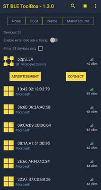
Then, scan and connect the device called p2pS_XX (where XX is replaced by the last byte of the BD address) to the application.
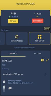
Once the Bluetooth® LE connection is established and the notification is enabled by the smartphone (by clicking on P2P server icon):
- LED_C value can be modified by clicking on the LED button on smartphone interface, the green LED of the board is switched On/Off accordingly.
- Pressing USER button on the board while connected sends a SWITCH_C notification to the smartphone and the switch level is updated on the smartphone interface.
- Pressing USER button on the board while not connected clears the bonded device list of the platform.
Bluetooth® LE P2P server VS Bluetooth® LE P2P client
At least two platforms are required, one flashed with the Bluetooth® LE P2P server application and one with the Bluetooth® LE P2P client application.
- On Bluetooth® LE P2P the client side:
- Pressing USER button on the Bluetooth® LE P2P client platform while not connected, starts a scan procedure, and connection is done if a Bluetooth® LE P2P server platform is found.
- Pressing USER button on the Bluetooth® LE P2P client platform while connected, sends a GATT event to the Bluetooth® LE P2P server platform in order to switch On/Off the server green LED.
- On the Bluetooth® LE P2P server side:
- Pressing USER button on the Bluetooth® LE P2P server side while connected sends a SWITCH_C notification to the Bluetooth® LE P2P client platform and toggles the green LED on the client side.
- Pressing USER button on the board while not connected clears the bonded device list of the platform.
Bluetooth® LE P2P server VS Web Bluetooth® Interface
Open ST Web Bluetooth® Interface
from a laptop or a smartphone with a Bluetooth® LE connection activated.
Then, scan and connect the device called p2pS_XX (where XX is replaced by the last byte of the BD address) to the application.
Once the Bluetooth® LE connection is established and the notification is enabled by the Web Bluetooth® Interface (by clicking on the Bluetooth® LE P2P server icon),
enable notifications by clicking on Notify OFF button.
- LED_C value can be modified by clicking on the Light OFF/ON button on the interface, the green LED of the board is switched On/Off accordingly.
- Pressing USER button on the board while connected sends a SWITCH_C notification to the interface and the switch level is updated on the interface (if notifications have been enabled).
- Pressing USER button on the board while not connected clears the bonded device list of the platform.
4.3. Project structure
Software project structure with the most important parts:
| p2pServer and p2pClient project structures |
|---|
API descriptions are available in the following page: X-CUBE-ST67W61 Architecture.
4.4. Build and Install
Refer to build and load chapter to details on how to build and download on the device.
4.5. User setup
4.5.1. ST67W6X default configuration
The default System configuration can be modified in "ST67W6X/Target/w6x_config.h":
/** NCP power save mode : 0: NCP stays always active / 1: NCP goes in low power mode when idle */
#define W6X_POWER_SAVE_AUTO                     0

/** NCP clock mode : 1: Internal RC oscillator, 2: External passive crystal, 3: External active crystal */
#define W6X_CLOCK_MODE                          1
Note: External clock oscillator must be used to support Bluetooth® LE in low power mode, if W6X_POWER_SAVE_AUTO is set to 1 but clock mode is not correct W6X_Ble_Init() API disable the low power.
The default Bluetooth® LE configuration can be modified in the "ST67W6X/Target/w6x_config.h" file:
/** Bluetooth® LE advertising name */
#define W6X_BLE_NAME                            "p2pS"
The AT driver can be configured in "ST67W6X/Target/w61_driver_config.h":
/** Maximum number of detected peripheral during the scan. Cannot be greater than 50 */
#define W61_BLE_MAX_DETECTED_PERIPHERAL         10

/** Enable/Disable BLE module logging */
#define BLE_LOG_ENABLE                          1

/** Maximum SPI buffer size */
#define W61_MAX_SPI_XFER                        1520

/** Debugging only: Enable AT log, i.e. logs the AT commands incoming/outcoming from/to the NCP */
#define W61_AT_LOG_ENABLE                       0

/** Enable/Disable System module logging */
#define SYS_LOG_ENABLE                          1
Additionally, some other options can be modified in the "ST67W6X/Target" directory with different configuration files as below:
- logging_config.h: This file provides configuration for the logging component to set the log level.
- shell_config.h: This file provides configuration for shell component.
- w6x_config.h: This file provides configuration for the W6X APIs (used during init).
- w61_driver_config.h: This file provides configuration for the W61 configuration module.
All available defines are available in template directory "Middlewares/ST/ST67W6X_Network_Driver/Conf"
4.5.2. Application configuration
The logging output mode can be modified in "Appli/App/app_config.h":
/** Select output log mode [0: printf / 1: UART / 2: ITM] */
#define LOG_OUTPUT_MODE             LOG_OUTPUT_UART
The host low-power mode can be modified in "Appli/App/app_config.h":
/** Low power configuration [0: disable / 1: sleep / 2: stop / 3: standby] */
#define LOW_POWER_MODE              LOW_POWER_SLEEP_ENABLE
The host debugger pins can be modified in "Appli/App/app_config.h":
/**
* Enable/Disable MCU Debugger pins (dbg serial wires)
* @note by HW serial wires are ON by default, need to put them OFF to save power
*/
#define DEBUGGER_ENABLED            1
4.6. Bluetooth® LE P2P client solutions
4.6.1. ST BLE ToolBox application
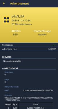
Once the Bluetooth® LE P2P server application is installed on the ST67W611M1 + STM32U5 platform, launch the ST BLE ToolBox smartphone application. The application starts scanning and allows to see advertisement data or to connect to the device. Once the device is connected, an interface allows to switch On/Off the green LED of the platform, and a notification reflects the Switch_C characteristic status.
| Bluetooth® LE P2P application on ST BLE ToolBox | ||
|---|---|---|
4.6.2. Web Bluetooth® Interface
In order to interface with the Bluetooth® LE Peer to Peer server embedded application, a web interface has been developed by STMicroelectronics and is available at the following link ST Web Bluetooth® Interface accessible from computer, table or smartphone.
Enable the Bluetooth® connection of the device, click on "Connect" button and select p2pS_[...] device:
| Connection from Web Bluetooth® |
|---|
Once connected, click on the P2P Server button to open the Peer to Peer dedicated interface:
| Bluetooth® LE P2P server interface |
|---|
Access Bluetooth® LE P2P server interface by clicking (1).
Once the Bluetooth® LE P2P server interface is opened, click on (2) to switch On/Off the green LED of the board, the status of the LED is also displayed in (3). (4) allows enabling/disabling SWITCH characteristic notifications. If the notifications are enabled, (5) reflects the SWITCH characteristic status. This status changes by clicking on USER button of the platform.
4.6.3. Bluetooth® LE P2P client embedded application
At startup, start a scan by pressing USER button of the Bluetooth® LE Peer To Peer client platform.
If a Bluetooth® LE Peer to Peer server device is detected, the client initiates the connection with it, then starts the services and characteristics discovery process, and identify Bluetooth® LE Peer to Peer service and its characteristics by their UUID.
Once connected, the Bluetooth® LE Peer To Peer client application:
- By pressing SW1 USER button, write a message to toggle the green LED of the Bluetooth® LE P2P server
- Receive notification to toggle the on-board green LED from remote Bluetooth® LE P2P server application
If no Bluetooth® LE Peer to Peer server is connected, relaunch a scan by pressing the USER button.
4.7. Memory footprint
| Module | Description |
|---|---|
| [Driver] HAL/CMSIS/BSP | STM32 CMSIS Cortex, HAL and LL, Board Specific Package drivers |
| [Project] Core | Native STM32 core components |
| [Project] App | Main part of the application |
| [Project] Target | Configuration files for ST67W6X_Network_Driver component |
| [MW] ST67W6X_Network_Driver | Core and API System and Bluetooth® LE components Util/Logging: Utility to process shell and trace messages onto the UART interface (can be changed by ITM) |
| [MW] FreeRTOS | FreeRTOS kernel source |
| [Utility] lpm | Tiny Low-Power Management |
| [Toolchain] Startup | Int_vect, init routines, init table, CSTACK and HEAP |
| [Toolchain] EWARM Libraries | Native compiler libraries |
These values depend on the chosen toolset, and they can change in next releases.
4.7.1. ROM/Flash memory footprint
The picture below shows the sum of the Read Only memory (flash) of the Bluetooth® LE P2P applications.
The picture below shows the middleware ST67W6X_Network_Driver read-only memory (flash) used by the Bluetooth® LE P2P applications.
4.7.2. Read Write (RW) memory footprint
The picture below shows only the sum of the static read/write memory (static RAM) of the Bluetooth® LE P2P applications.
5. References


