For the sake of brevity, we will refer to Realistic Use Cases (RUC) as an abbreviation throughout this discussion.
1. Introduction
The Zigbee protocol has been developed for mesh networking capabilities of the Internet of Things (IoT), such as home and building automation [1]. In the context of home automation, the Realistic Use Cases involves creating and maintaining a Zigbee mesh that runs 24 hours a day with a mix of different functionalities. The goal is to expose our product to real-life scenarios that customers encounter in order to identify potential problems and enhance our product maturity.
2. Typical Home Automation Zigbee Network
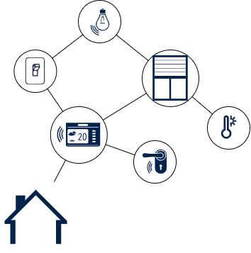
A typical home automation Zigbee network consists of a Zigbee HUB, which acts as the Coordinator for all the devices in the network. The network can include various devices such as lights, sensors, windows, etc.. Zigbee HUB communicates with all the devices in the network, allowing users to control them remotely through a smartphone applications or voice commands like Amazon Alexa.
For more information about Zigbee network, refer to Wiki: Zigbee Network
| Home Automation Zigbee Network Example |
|---|
3. Zigbee RUC with STM32WB
The STM32CubeWB MCU Package[2] provides several Zigbee applications that can be used to extend the main network.
For the applications with Coordinator, modify them and remove Coordinator part to transform it in ZR/ZED to run correctly in the RUC environment.
We have implemented three applications that reflect real use cases:
4. Zigbee RUC SW architecture
To provide a more user-friendly working environment, the code architecture was modified. This new architecture enhances scalability, ease of maintenance and debugging. In fact, some templates are developed to create Zigbee applications effortlessly.
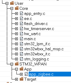
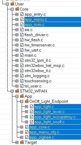
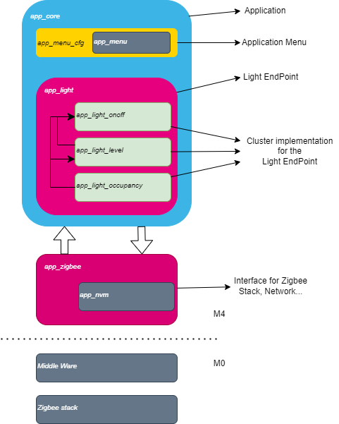
Previously, Zigbee stack and clusters were controlled from a single file called app_zigbee.c. In the RUC source code version, it has been split into multiple files and folders:
- app_menu.c : software driver to create a colorful menu in the terminal via UART interface(like Teraterm/Termite)[6]
- app_nvm.c : service to save Zigbee informations, enabling retrieval of the application’s state after reset or wake-up (Zigbee network, security keys, binding table, persistable attributes, etc.) [7]
- EndPoint Folder : containing all files needed for the Endpoint and their associated clusters and their interactions (ex app_light.c, app_light_onoff.c)
- app_core.c : the main part where the application runs (e.g.: start Zigbee stack and call services).
- app_menu_cfg.c : menu configuration file for the Application using app_menu above
- app_zigbee.c : manages the Zigbee primary functions to initialize stack, join network, binding, etc.
| Modification of code Architecture | ||
|---|---|---|
| Standard source code | RUC source code | RUC SW Layers |
Software Menu
This software driver enables a colorful menu via the UART. In all RUC examples, the implementation is almost the same for all boards.
It displays whether messages come from M4 or M0, the file name from which the message was emitted, and allows switching to the next/previous menu element or executing the current element on button press.
To avoid losing Menu, it appears always at the top of the Terminal.
| Example of display on UART terminal |
|---|
Different time presses are used for different actions; a short press to move left/right in menu choices and long/middle press to back to the previous menu or execute an action.
- Switch1 /User 1: short press moves to left item, long press back to previous menu
- Switch 3/User 2: short press moves to right item, long press launch action (enter sub-menu, launch command)
When selected, a submenu displays in yellow surrounded by [...], while a command to launch is in yellow only.
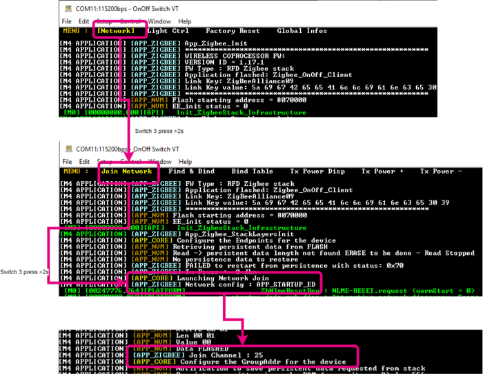
As seen below, from the main menu it appears the [Network] submenu. From this submenu, it is possible to launch the Join Network command.
| Soft Menu |
|---|
5. How To Join Zigbee Network
In the RUC examples, to set up the Zigbee Network use the procedure described in this section.
By default, it is assumed that a Coordinator will be in charge of creating the network and that you wish to add a new device (such as a light switch or other).
The procedure below describes the steps on Nucleo Board [8]. Note that it is same on a DK board [9].
Coordinator side
- Select the [Network] sub-menu (press 2s on Switch 3)
- Launch the Permit join request action (press 2s on Switch 3)
- Displays in the Terminal if the action was launched correctly and how many time to executes the join Network on the new device
| Permit Join |
|---|
New Device side
- Select the [Network] sub-menu (press 2s on Switch 3)
- Launch the Join Network action (press 2s on Switch 3)
- If all steps are done correctly, you will get a message on the device: Join Channel : xx.
- Otherwise, the device stays in beacon states to join a network available.
Don't forget to back to main menu (press 2s on Switch 1)
| Join Network |
|---|
6. How To bind devices
This section describes only how to bind two devices using Finding&Binding procedure via Soft Menu.
Please see Wiki: Zigbee Binding, for more information on the Zigbee binding functionality.
For all RUC applications, the process is the same.
Target Side
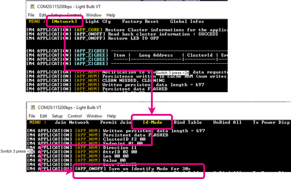
- Select the [Network] sub-menu (press 2s on Switch 3)
- Launch the Id-Mode action (press 2s on Switch 3)
- Displays in the Terminal if the action was launched correctly and how many time to executes the Find&Bind on the initiator
| Identify Mode start |
|---|
Initiator
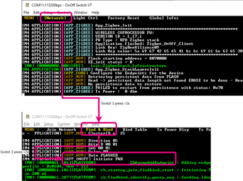
- Select the [Network] sub-menu (press 2s on Switch 3)
- Launch the Find&Bind action (press 2s on Switch 3)
- Displays in the Terminal if the action was launched correctly
- Wait the binding
| Launch Find&Bind |
|---|
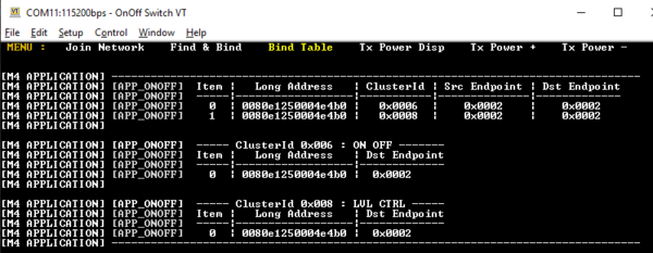
Please find below an example of result after binding failed or successfully:
| Binding Failed, no response |
|---|
| Initiator |
| Binding Succeeded |
| Initiator |
| Target |
7. Acronyms and definitions
| Term | Definition |
|---|---|
| ZC | Zigbee Coordinator |
| ZR | Zigbee Router |
| ZED | Zigbee End Device |
| RUC | Realistic Use Case |
| DK | Discovery Kit |
8. References
