1. Introduction
This document describes how to optimize the configuration parameters for a 6-step sensor-less algorithm. The goal is to obtain a smooth and fast startup procedure, but also a stable closed-loop behavior. Additionally, the document also explains how to reach a proper switch between back-emf zero-crossing detection during PWM OFF-time and PWM ON-time when spinning the motor at a high speed with a voltage driving mode technique. For further details about the 6-step firmware algorithm and the voltage/current driving technique, refer to the related user manual included in the X-CUBE-MCSDK [1] documentation package.
2. Acronyms and abbreviations
| Acronym | Description |
| MCSDK | Motor control software development kit (X-CUBE-MCSDK) |
| HW | Hardware |
| IDE | Integrated development environment |
| MCU | Microcontroller unit |
| GPIO | General purpose input output |
| ADC | Analog-to-digital converter |
| VM | Voltage mode |
| SL | Sensors-less |
| BEMF | Back electromotive force |
| FW | Firmware |
| ZC | Zero-crossing |
| GUI | Graphical user interface |
| MC | Motor control |
| OCP | Over current protection |
| PID | Proportional-integral-derivative (controller) |
| SDK | Software development kit |
| UI | User interface |
| MC workbench | Motor control workbench tool, part of MCSDK |
| MC profiler | Motor control profiler tool, part of MCSDK |
| Motor Pilot | Motor Pilot tool, part of MCSDK |
3. Overview
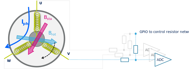
In the 6-step sensor-less driving mode, the firmware exploits the back electromotive force (BEMF) sensed at the floating phase. The position of the rotor is obtained by detecting the zero-crossing of the BEMF. This is commonly done using an ADC as shown in Figure 1. In particular, when the magnetic field of the rotor crosses the high-Z phase, the corresponding BEMF voltage changes its sign (zero-crossing). The BEMF voltage can be scaled at the ADC input, thanks to a resistor network that divides the voltage coming from the motor phase.
However, since the BEMF signal is proportional to the speed, the rotor position cannot be determined at startup, or at very low speed. Therefore, the motor must be accelerated in an open-loop until a sufficient BEMF voltage is reached. That BEMF voltage allows the synchronization of the step commutation with the rotor position.
In the following paragraphs, the startup procedure and the closed-loop operation, together with the parameters to tune them, are described.
3.1. BEMF zero-crossing detection
The Back-EMF waveform of brushless motor changes along with the rotor position and speed and is in a trapezoidal shape. Figure 2 shows the waveform of the current and back-EMF for one electrical period, where the solid line denotes the current (ripples are ignored for the sake of simplicity), the dashed line represents the back electromotive force, and the horizontal coordinate represents the electric perspective of motor rotation.
The middle of every two phase-switching points corresponds to one point whose back electromotive force polarity is changed: the zero-crossing-point. Once the zero-crossing point is identified, the phase-switching moment is set after an electrical delay of 30°.
To detect the zero-crossing of the BEMF, the center tap voltage has to be known. The center tap is equal to the point where the three motor phases are connected together. Some motors make the center tap available. In other cases, it can be reconstructed through the voltage phases. The 6-step algorithm that is described here takes advantage from the presence of a BEMF sensing network connected to the motor phases that allows to calculate the center tap voltage.
Two different strategies are available for the identification of the zero-crossing point:
• Back-EMF sensing during the PWM OFF-time
• Back-EMF sensing during the PWM ON-time (currently supported in voltage mode only)
During the PWM OFF-time, the floating phase voltage is acquired by the ADC. Since no current is flowing in the floating phase, and the other two are connected to the ground, when the BEMF crosses zero in the floating phase, it has equal and opposite polarity on the other phases: the center tap voltage is therefore zero. Hence, the zero-crossing point is identified when the ADC conversion raises above, or falls below, a defined threshold.
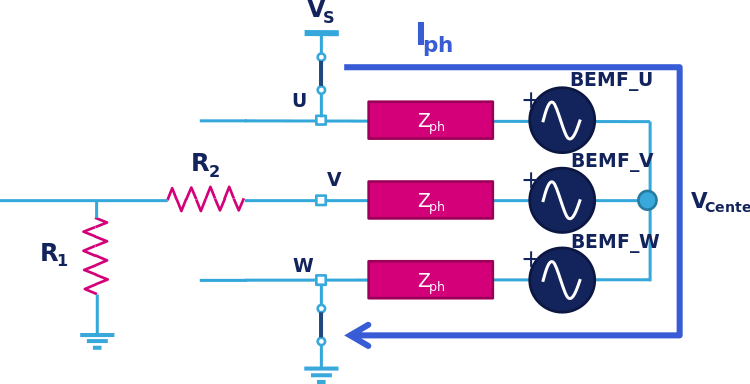
On the other hand, during the PWM ON-time, one phase is connected to the bus voltage, and another to the ground (Figure 3). In this condition, the center tap voltage reaches half of the bus voltage value when the BEMF in the floating phase is zero. Like previously, the zero-crossing point is identified when the ADC conversion raises above (or falls below) a defined threshold. The latter corresponds to VS / 2.
3.2. BEMF sensing network design
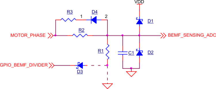
In Figure 4, the commonly used network to sense the BEMF is shown. Its purpose is to divide the motor phase voltage to be properly acquired by the ADC. The R2 and R1 values must be chosen according to the bus voltage level. The user has to be aware that implementing a R1 / (R2 + R1) ratio much lower than needed, the BEMF signal may result in too low and the control not robust enough.
On the other hand, a ratio higher than needed would lead in frequent turning-on/off of the D1 protection diodes whose recovery current may inject noise. The recommended value is:
Very low values for R1 and R2 must be avoided to limit current tapped from the motor phase.
R1 is sometimes connected to a GPIO instead of GND. It allows the network to be runtime enabled or disabled.
In the 6-step firmware, the GPIO is always in reset state and the network is enabled. However, the eventual presence of D3 must be considered when setting the BEMF thresholds for sensing during the PWM on-time: it usually adds 0.5÷0.7 V to the ideal threshold.
C1 is for filtering purposes and must not limit the signal bandwidth in the PWM frequency range.
D4 and R3 are for fast discharge of BEMF_SENSING_ADC node during the PWM commutations, especially in high voltage boards.
The D1 and D2 diodes are optional and must be added only in case of risk of violating the BEMF sensing ADC channel maximum ratings.
4. Optimization of control algorithm parameters
4.1. Startup procedure
The startup procedure is usually made up of a sequence of three stages:
1. Alignment: the rotor is aligned at a predetermined position.
2. Open-loop acceleration: the voltage pulses are applied in a predetermined sequence to create a magnetic field that causes the rotor to start rotating. The sequence’s rate is progressively increased to allow the rotor to reach a certain speed.
3. Switch-over: once the rotor has reached a certain speed, the algorithm switches to a closed-loop 6-step control sequence to maintain control of the motor's speed and direction.
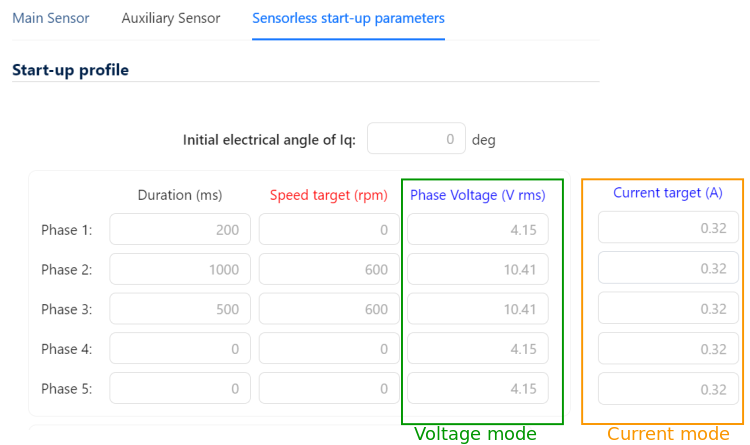
As shown in Figure 5, the user can customize the startup parameters in the MC workbench before generating the code. Two different driving modes are available:
• Voltage mode: the algorithm controls the speed by varying the duty cycle of the PWM applied to the motor phases. A target phase voltage is defined for each segment of the startup profile.
• Current mode: the algorithm controls the speed by varying the current that flows in the motor phases. A current target is defined for each segment of the startup profile.
4.1.1. Alignment
In Figure 5, the phase 1 always corresponds to the alignment step. The rotor is aligned to the 6-step position closest to the "initial electrical angle".
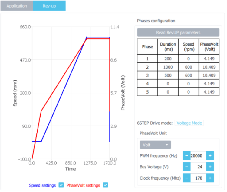
It is important to note that, by default, the duration of the phase 1 is 200 ms. During this step, the duty cycle is linearly increased to reach the target voltage phase. It corresponds to the current phase, when the current driving mode is selected. However, with bulky motors or in case of high inertia, the suggested duration, or even the target voltage/current phase, may not be sufficient to properly start the rotation.
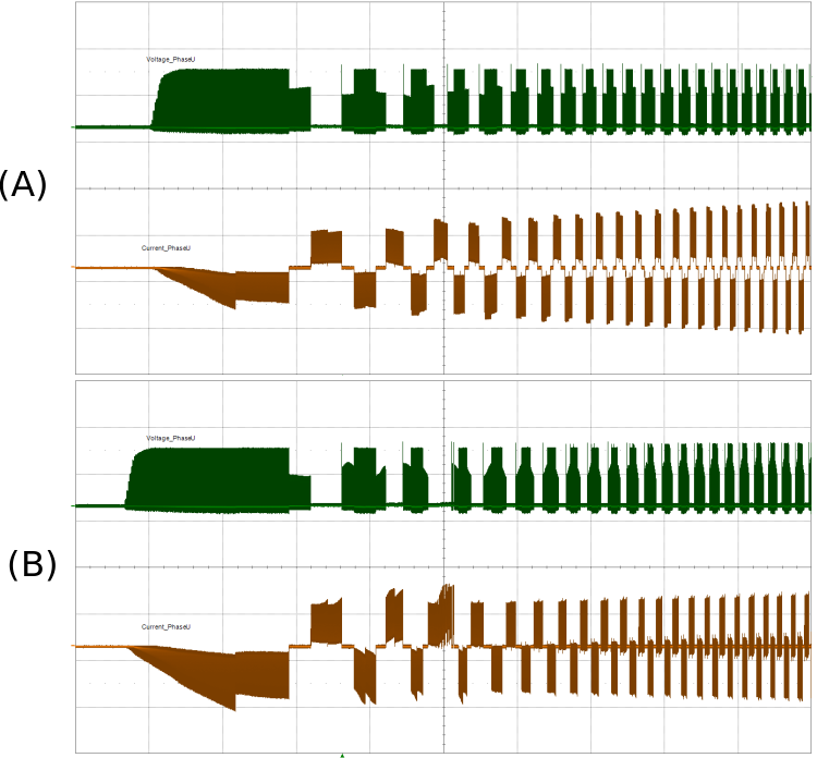
In Figure 6, a comparison between a wrong alignment condition and a proper one is provided. If the target value or duration of phase 1 is not enough to force the rotor in the starting position, the user can see the motor vibrating without starting to rotate. Meanwhile, the current absorption increases. During the first period of the startup procedure, the current increases, but the torque is not sufficient to overcome the inertia of the motor. At the top of the Figure 6 (A), the user can see the current increasing. However, there is no evidence of BEMF: the motor is then stalled. Once the acceleration step is started, the uncertain position of the rotor prevents the algorithm to complete the startup procedure and run the motor.
Increasing the voltage/current phase during phase 1 may fix the issue.
In voltage mode, the target voltage during the startup can be customized with the Motor Pilot without the need to regenerate the code. In the Motor Pilot, in the rev-up section, the same acceleration profile of Figure 1 is reported (see Figure 7). Note that here the voltage phase can be shown as the pulse set into the timer register (S16A unit), or as corresponding to the output voltage (Vrms unit).
Once the user finds the proper values that suit best the motor, these values can be implemented into the MC workbench project. It allows regenerating the code to apply the default value. The below formula explains the correlation between voltage phase in Vrms and S16A units.
Where
In current mode, in the Motor Pilot GUI, the target current is only shown in S16A. Its conversion in ampere depends on the shunt value and the amplification gain used in the current limiter circuitry.
4.1.2. Open-loop acceleration
In Figure 5, the phase 2 corresponds to the acceleration phase. The 6-step sequence is applied to speed up the motor in an open-loop, hence, the rotor position is not synchronized with the 6-step sequence. The current phases are then higher than optimum and the torque is lower.
In the MC workbench (Figure 5), the user can define one or more acceleration segments. In particular, for a bulky motor, it is recommended to accelerate it with a slower ramp to overcome the inertia before performing a steeper ramp. During each segment, the duty cycle is linearly increased to reach the final target of the voltage/current phase of that segment. Thus, it forces the commutation of the phases at the corresponding speed indicated in the same configuration table.
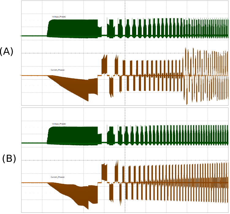
In Figure 8, a comparison between an acceleration with a voltage phase (A) too low and a proper one (B) is provided.
If the target voltage/current of one phase or its duration is not enough to allow the motor to reach that corresponding speed, the user can see the motor stop spinning and start vibrating. At the top of Figure 8, the current suddenly increases when the motor stalls while, when properly accelerated, the current increases without discontinuities. Once the motor stops, the startup procedure fails.
Increasing the voltage/current phase may fix the issue.
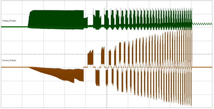
On the other hand, if the voltage/current phase defined is too high, since the motor is running inefficiently in open-loop, the current may rise and reach the overcurrent. The motor suddenly stops, and an overcurrent alarm is shown by the Motor Pilot. The behavior of the current is shown in Figure 9.
Decreasing the voltage/current phase may fix the issue.
As the alignment step, the target voltage/current can be runtime customized during the startup with the Motor Pilot without the need to regenerate the code. Then, it can be implemented into the MC workbench project when the proper setting is identified.
4.1.3. Switch-over
The last step of the startup procedure is the switch-over. During this step, the algorithm exploits the sensed BEMF to synchronize the 6-step sequence with the rotor position. The switch-over starts in the segment indicated in the parameter underlined in Figure 10. It is configurable in the sensor-less startup parameter section of the MC workbench.
After a valid BEMF zero-crossing detection signal (to fulfill this condition see section 2.1), the algorithm switches to a close-loop operation. The switch-over step may fail due to the following reasons:
• Switch-over speed is not properly configured.
• PI gains of the speed loop are too high.
• Thresholds to detect the BEMF zero-crossing event are not properly set.
4.1.3.1. Switch-over speed not properly configured
The speed at which the switch-over starts is by default the same as the initial target speed that can be configured in the drive setting section of the MC workbench. The user has to be aware that, as soon as the speed loop is closed, the motor is instantaneously accelerated from the switch-over speed to the target speed. If these two values are very far apart, an overcurrent failure may occur.
4.1.3.2. PI gains of the speed loop too high
During switch-over, the algorithm moves from forcing a predefined sequence to measure the speed and calculate the output values accordingly. Thus, it compensates the actual speed that is the result of the open-loop acceleration. If the PI gains are too high, a temporary instability can be experienced, but it can lead to overcurrent failure if exaggerated.
Figure 11 shows an example of such instability during the transition from open-loop to close-loop operation.
4.1.3.3. Wrong BEMF thresholds
If wrong BEMF thresholds are set, the zero-crossing is detected, either in advance, or late. This provokes two main effects:
1. The waveforms are asymmetric and the control is inefficient. It leads to high ripples of torque (Figure 12).
2. The speed loop becomes unstable by trying to compensate for the ripples of torque.
The user would experience unstable speed control and, in the worst cases, a desynchronization of the motor driving with the control leading to an overcurrent event.
The proper setting of BEMF thresholds is crucial for good performance of the algorithm. Thresholds also depend on the bus voltage value and the sensing network. Refer to section 2.1 to check how to align voltage levels to the nominal one set in the MC workbench is recommended.
4.2. Closed-loop operation
If the motor completes the acceleration phase, the BEMF zero-crossing is detected. The rotor is synchronized with the 6-step sequence and a closed-loop operation is obtained. However, further parameter optimization can be carried out to improve the performances. For instance, as described in the previous paragraph 3.1.3 (“Wrong BEMF thresholds”), the speed loop, even if working, may appear unstable and BEMF thresholds may need some refinement. Additionally, the following aspects have to be considered if a motor is requested to work at high speed or driven with a high PWM duty cycle:
• PWM frequency
• Speed loop PI gains
• Demagnetization blanking period phase
• Delay between zero-crossing and step commutation
• Switch between PWM OFF-time and ON-time sensing
4.2.1. PWM frequency
The sensor-less 6-step algorithm performs an acquisition of the BEMF every PWM cycle. To properly detect the zero-crossing event, a sufficient number of acquisitions is required. As a role of thumb, for proper operation, at least 10 acquisitions over 60 electrical angles grant good and stable rotor synchronization.
Therefore:
where:x
4.2.2. Speed loop PI gains
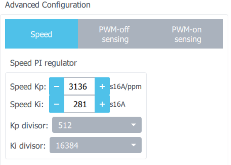
Speed loop PI gains affect the responsiveness of the motor to any command of acceleration or deceleration. A theoretical description of how a PID regulator works is beyond the scope of this document. However, the user must be aware that speed loop regulator gains can be changed at runtime through the Motor Pilot and be adjusted as desired.
4.2.3. Demagnetization blanking period phase
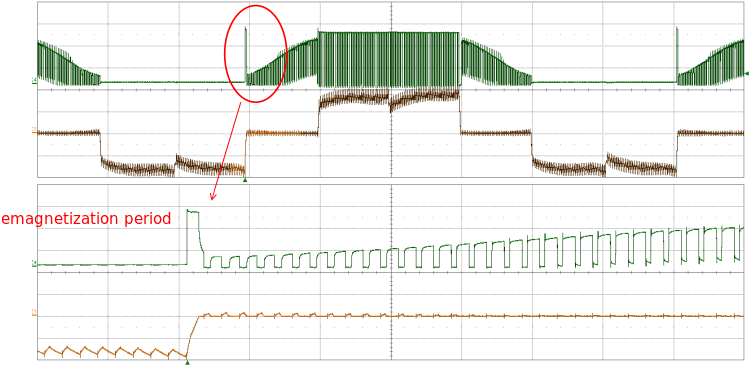
The demagnetization of the floating phase is a period after the change of energization phases during which, due to the current discharge (Figure 14), the Back-EMF reading is not reliable. Therefore, the algorithm must ignore the signal before it is elapsed.
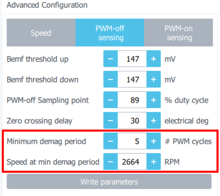
This period is defined in the MC workbench as a percentage of a step (60 electrical degrees) and can be runtime changed through the Motor Pilot as shown in Figure 15. The higher the motor speed, the faster the demagnetization period. The demagnetization by default reaches a lower limit set to three PWM cycles at 2/3 of the maximum rated speed.
If the inductance phase of the motor is low and does not require much time to demagnetize, the user can reduce the masking period or the speed at which the minimum period is set.
However, it is not recommended to lower the masking period below 2 - 3 PWM cycles because the control can incur sudden instability during step commutation.
4.2.4. Delay between BEMF zero-crossing and step commutation
Once the BEMF zero-crossing event has been detected, the algorithm normally waits 30 electrical degrees until a step sequence commutation (Figure 16). In this way, the zero-crossing is positioned at the midpoint of the step to target the maximum efficiency.
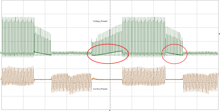
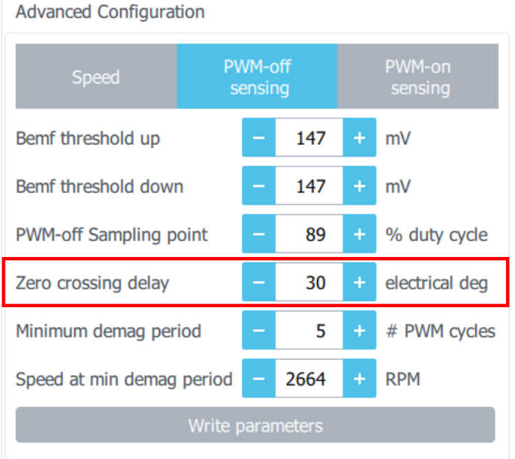
Since the accuracy of the zero-crossing detection depends on the number of acquisitions, hence on the PWM frequency (see section 3.2.1), the accuracy of its detection may become relevant at high speed. It then generates an evident asymmetricity of the waveforms and the distortion of the current (see Figure 17). This can be compensated by reducing the delay between zero-crossing detection and step commutation. Zero-crossing delay can be runtime changed by the user through the Motor Pilot as shown in Figure 18.
4.2.5. Switch between PWM OFF-time and ON-time sensing
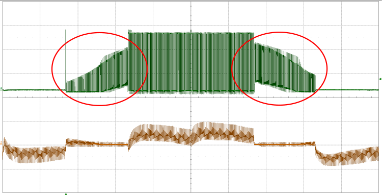
While increasing the speed or the load current (that is to say motor output torque), the duty cycle of the PWM driving increases. Thus, the time for sampling the BEMF during the OFF-time is reduced. To reach 100% of the duty cycle, the ADC conversion is triggered during the ON time of the PWM, thus switching from BEMF sensing during the PWM OFF-time to PWM ON-time.
A wrong configuration of the BEMF thresholds during ON-time leads to the same issues described in the section 3.1.3 (“Wrong BEMF thresholds”).
By default, BEMF ON-sensing thresholds are set to half of the bus voltage (see section 2.1). The user must consider that actual thresholds depend on the bus voltage value and sensing network. Follow the indications in section 2.1 and make sure to align the voltage level to the nominal one set in the MC workbench.
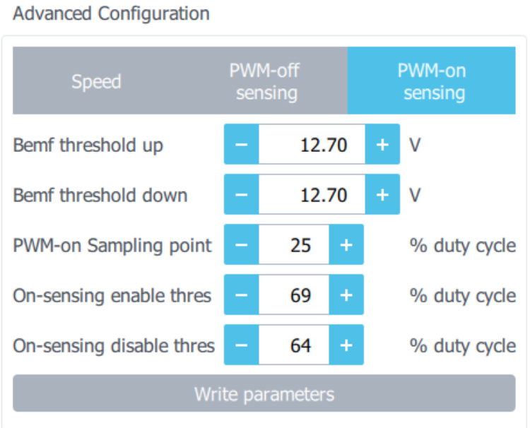
Values of the thresholds and PWM duty cycle at which the algorithm swaps between OFF and ON-sensing are runtime configurable through the Motor Pilot (Figure 19) and are available in voltage mode driving only.
5. Troubleshooting
What do I have to take care of to properly spin a motor with a sensor-less 6-step algorithm?'
Spinning a motor with a sensor-less 6-step algorithm implies being able to properly detect the BEMF signal, accelerate the motor, and synchronize the rotor with the control algorithm.
The proper measurement of the BEMF signals lies in the effective design of the BEMF sensing network (see section 2.1).
The target voltage (voltage mode driving) or current (current mode driving) during the startup sequence depends on the motor parameters. The definition (and eventually the duration) of the voltage/current phase during alignment, acceleration, and switch-over steps are crucial for a successful procedure (see section 3).
In the end, the synchronization of the rotor and the ability to increase the speed motor up to the rated speed depends on the optimization of the PWM frequency, BEMF thresholds, demagnetization period and delay between zero-crossing detection and step commutation, as described in section 3.2
'What is the right value of the BEMF resistor divider?'
The user has to be aware that a wrong BEMF resistor divider value may remove any chance of properly driving the motor. For further details on how to design the BEMF sensing network, refer to section 2.1.
How do I configure the startup procedure?'
To optimize the startup process, it is recommended to increase the duration of each step of the rev-up phase to several seconds. It is then possible to understand whether the motor properly accelerates, or at which speed/step of the open-loop procedure it fails.
It is not advisable to accelerate a high inertia motor with a too steep ramp.
If the configured voltage phase or current phase is too low, the motor stalls. If it is too high, the overcurrent is triggered. Gradually increasing the voltage phase (voltage mode driving) or current (current mode driving) during the alignment and acceleration steps allow the user to understand the range of working of the motor. Indeed, it helps to find the optimum.
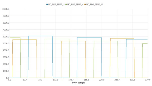
When it comes to switching to a closed-loop operation, the gains of the PI must be reduced at first to exclude that a loss of control or instability is due to speed loop. At this point, being sure that the BEMF sensing network is properly designed (see section 2.1) and the BEMF signal properly acquired is crucial. The user can access the reading of the BEMF, and plot it in the Motor Pilot (see Figure 20) by selecting the available registers BEMF_U, BEMF_V and BEMF_U in the ASYNC plot section of the tool.
Once the motor is in the Run state, the speed loop controller gains can be optimized. For further details or parameter optimization, see sections 3 and 3.2.
What can I do if the motor does not move at startup?'
At startup, a linearly increasing voltage (voltage mode driving) or current (current mode driving) is provided to the motor phases. The goal is to align it at a known and predefined position. If the voltage is not high enough (especially with motors with a high inertia constant), the motor does not move and the procedure fails. For further information about possible solutions, refer to section 3.1.1.
What can I do if the motor does not complete the acceleration phase?'
Like for the alignment phase, the motor is accelerated in an open-loop by applying a linearly increasing voltage (voltage mode driving) or current (current mode driving) to the motor phases. Default values do not consider eventual applied mechanical load, or motor constants are not accurate and/or known. Therefore, the acceleration procedure may fail with a motor stall or an overcurrent event. For further information about possible solutions, refer to section 3.1.2.
Why does not the motor switch over into a closed speed loop?'
If the motor properly accelerates to target speed but it suddenly stops, something may be wrong in the BEMF threshold configuration or the PI controller gains. Refer to the section 3.1.3 for further details.
Why does the speed loop look unstable?'
An increase of the noise of the measurement with the speed is expected since the higher the speed is, the lower the number of BEMF samples for zero-crossing detection and, consequently, the accuracy of its calculation. However, an excessive instability of the speed loop may also be the symptom of wrong BEMF threshold or PI gains that are not properly configured as highlighted in section 3.1.3.
How can I increase the maximum reachable speed?'
Maximum reachable speed is usually limited by several factors: PWM frequency, loss of synchronization (due to excessive demagnetization period or wrong delay between zero-crossing detection and step commutation), inaccurate BEMF thresholds. For further details on how to optimize these elements, refer to sections 3.2.1, 3.2.3, 3.2.4 and 3.2.5.
Why does the motor suddenly stop at a certain speed?'
It is likely due to an inaccurate PWM on-sensing BEMF threshold configuration. Refer to section 3.2.5 for further details.
