This article describes how to easily modify the system-performance application generated using STM32Cube.AI to run power and energy measurements in an optimal configuration. it applies to the STM32 microcontrollers without neural processing unit. For the STM32N6x7 embedding an Arm Cortex®-M55 core together with a the Neural-ART Accelerator™ Neural Processing Unit (NPU), the application package x-cube-n6-ai-power-measurement provides the mean to measure VDDCORE on the STM32N6 discovery kit. Details are provided in the Readme.md of the package.
The system-performance application allows automatic running of inferences of a machine learning processing generated using STM32Cube.AI (neural network or traditional machine learning models). This allows direct measurement of the inference time on the target . It can also be used to measure power consumption, however, the default settings are not fully optimized for accurate measurement of power consumption due to processing only, excluding peripherals and power leakage on unused GPIOs. The NUCLEO-L4R5ZI is used as an example, but the process can be adapted to any board supported by STM32Cube.AI.
MLCommons™ consortium launched the MLPerf™ Tiny benchmark. ST submits results achieved with STM32Cube.AI. In the scope of MLPerf™ Tiny benchmark, a dedicated process is followed with reference models and reference measurement implementation based on EEMBC™ methodology. The reference STM32Cube.AI implementation is published on ST stm32ai-perf github.
1. Prerequisites
1.1. Hardware
- NUCLEO-L4R5ZI
- STM32 Power shield, Nucleo expansion board for power consumption measurement X-NUCLEO-LPM01A
- 2 Micro-USB to USB cables
1.2. Software
- X-Cube-AI version 7.0.0 or above
- STM32Cube IDE
- STM32CubeMonitor-Power
2. Project generation
2.1. Loading a pre-defined ioc
The next section describes how to start from STM32CubeMX to generate the project. Pre-defined STM32CUbeMX project Files ioc for some boards are to be provided in the near future on GitHub.
You can load them directly to the "Import your model" section and then go directly to the import model section. To load an ioc, select Files / Load Project:
2.2. Create a new project
Open STM32CubeMX and start the project using the board selector:
Select the board to use, in our case the NUCLEO-L4R5ZI, and create a project without initializing all peripherals with their default Mode:
2.3. Add X-CUBE-AI software pack
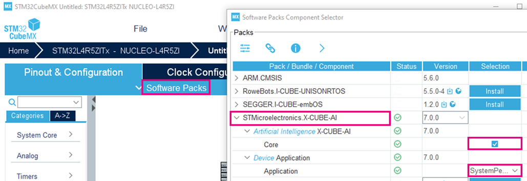
Select X-CUBE-AI software pack Core and System Performance application:
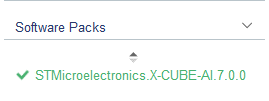
Click on X-CUBE-AI software pack:
If by default the peripherals parameters are not set for the best performance, the system warns you of this. Select 'yes' to make sure that the maximal frequency is used.
X-CUBE-AI configures default parameters to set the best performance as well as configuring the UART used to report performances.
You can check which UART is used by X-CUBE-AI to communicate with the board. It is the UART connected to the STLink embedded device which is seen from the PC as a Virtual Com Port once connected by USB. To do so open the Platform Settings panel:
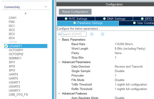
For the NUCLEO-L4R5ZI it is the LPUART1. You can also check the settings used by X-CUBE-AI for the specified UART in the Connectivity panel / Parameter Settings:
These settings must be used on PC the hyper terminal to communicate with the board when the system-performance application is running.
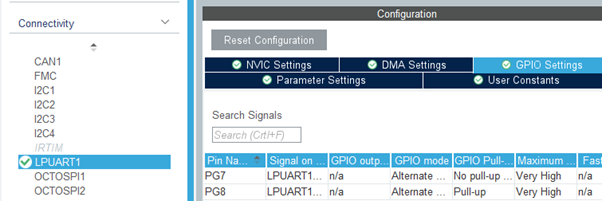
Identify the GPIOs used by the UART in the GPIO Settings panel:
For the NUCLEO-L4R5ZI, it is the PG7 and PG8 (Pin 7 and 8 of bank G).
2.4. Check / modify clock configuration
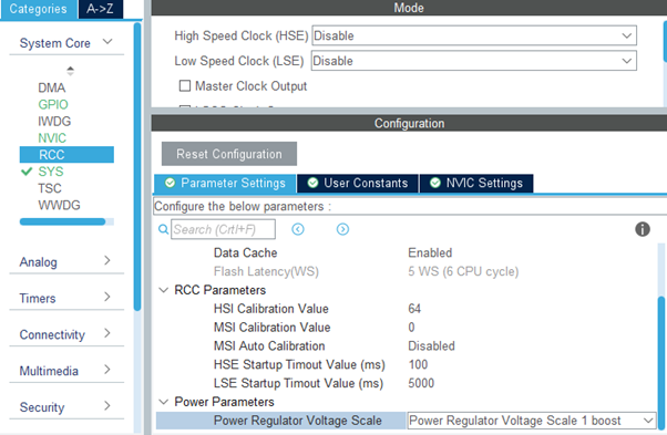
You can also open and modify the clock configuration, for instance to select a specific HCLK frequency or change the clock source (on STM32L4R5ZI Nucleo for instance from HSI to MSI). For convenience when setting the GPIOs, it is recommended to select HSI as source clock. If the HSE (external clock) is selected, be sure not to reset GPIOs connected to the external crystal RCC_OSC_IN and RCC_OSC_OUT. Note that on Nucleo boards the HSE crystal is generally not mounted by default . You can also check the clock setting in the System Core / RCC panel, and especially the Power Regulator Voltage Scale (see the 'Important notes' section for the STM32H747 case).
When using an SMPS for the power supply, make sure the right power regulator for the frequency is selected as well as other related parameters.
2.5. Reset not necessary GPIOs
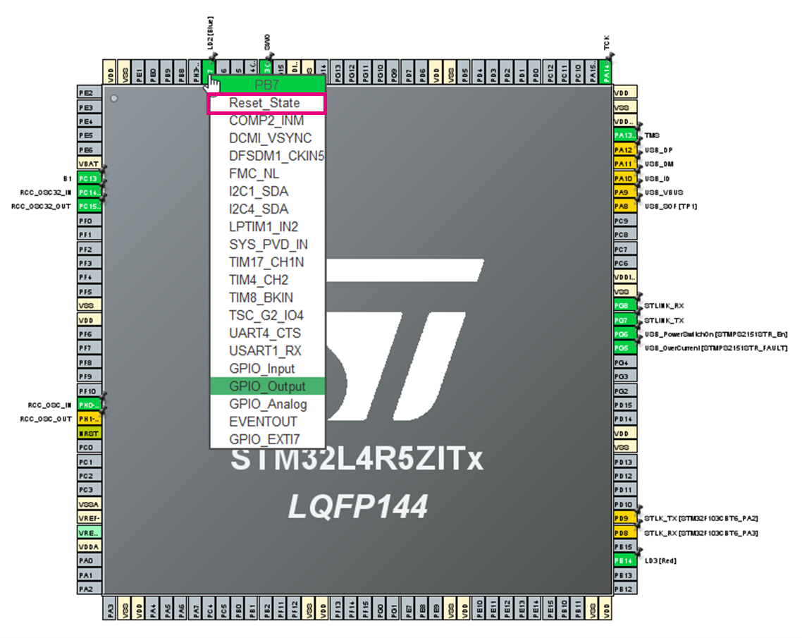
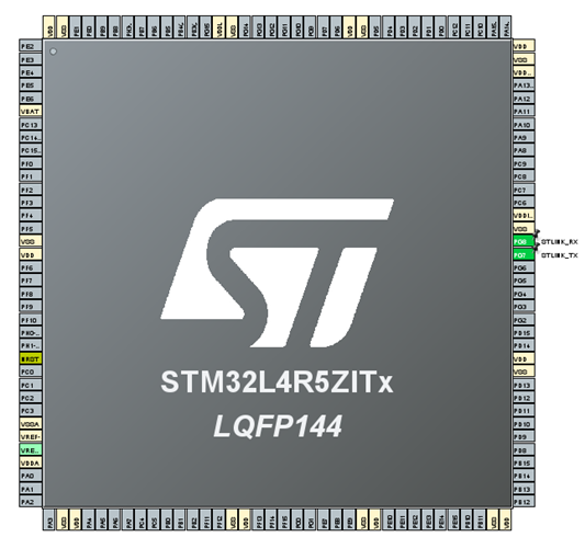
On the “Pinout & Configuration” view, reset all the unused GPIOs. All pins can be put in reset state except the STLINK_RX and STLINK_TX UART pins (PG7 and PG8 for NUCLEO-L4R5ZI configured by X-CUBE-AI), NRST and also the power and ground pins. Reset RCC_OSC_IN and RCC_OSC_OUT only if the HSE is not selected. On the NUCLEO-L4R5ZI example, this means changing the following configuration:
to the following one:
2.6. Importing your model into X-CUBE-AI
As usual with X-CUBE-AI, import the model you wish to analyze:
To optimize the RAM usage, it is advisable to select the "Use activation buffer for input buffer" and "Use activation buffer for the output buffer" options in the Advanced Settings panel:
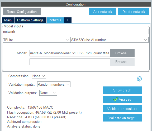
The total memory footprint for a given model shall consider not only the size of the weights (stored in Flash) and the size of the activations, input, output buffers. The size of the runtime code (Flash and RAM) shall also be considered. You can run an "Analyze" to get the full memory footprint of the model:
The library runtime memory footprint (Flash and RAM) is measured using STM32Cube IDE as toolchain.
2.7. System performance code generation
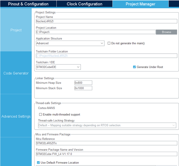
Open the Project Manager tab and specify a project name. Select the IDE, in this example we use STM32Cube IDE:
Select the Code Generator tab and check the “Set all free pins as analog (to optimize the power consumption)” option:
3. Project modification
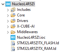
Once generated you can open the project with STM32Cube IDE:
The ioc can be reused to recover the settings in CubeMX and modify or generate new projects with new models without needing to reconfigure everything. A set of pre-configured iocs is to be provided on GitHub. You can do a first build of the project to check the generation.
Add the following functions for the NUCLEO-L4R5ZI to main.c (located in Core/Src) between the two tags “/* USER CODE BEGIN 0 */” and “/* USER CODE END 0 */”:
/* USER CODE BEGIN 0 */
/**
  * @brief Disable the clock of all GPIOs
  * @param None
  * @retval None
  */
void MX_GPIO_Disable(void)
{

  __HAL_RCC_GPIOA_CLK_DISABLE();
  __HAL_RCC_GPIOB_CLK_DISABLE();
  __HAL_RCC_GPIOC_CLK_DISABLE();
  __HAL_RCC_GPIOD_CLK_DISABLE();
  __HAL_RCC_GPIOE_CLK_DISABLE();
  __HAL_RCC_GPIOF_CLK_DISABLE();
  __HAL_RCC_GPIOG_CLK_DISABLE();
  __HAL_RCC_GPIOH_CLK_DISABLE();
}

/**
  * @brief Disable the VCOM UART
  * @param None
  * @retval None
  */
void MX_UARTx_DeInit(void)
{
  HAL_UART_DeInit(&hlpuart1);
  GPIO_InitTypeDef GPIO_InitStruct = {0};

  /*Configure GPIO pins : PG7, PG8 */
  GPIO_InitStruct.Pin = GPIO_PIN_7|GPIO_PIN_8;
  GPIO_InitStruct.Mode = GPIO_MODE_ANALOG;
  GPIO_InitStruct.Pull = GPIO_NOPULL;
  HAL_GPIO_Init(GPIOG, &GPIO_InitStruct);
}
/* USER CODE END 0 */
For boards other than NUCLEO-L4R5ZI, you need to adapt to:
- The number and identifications of GPIO banks; you can simply refer to the function MX_GPIO_Init in the main.c file, which enables the GPIO clocks so that the GPIOs can be set to analog mode.
- The UART handle used for the Virtual Com Port. It is also specified in main.c where the UART is configured and enabled. Refer to the “Private variable” and the UART_HandleTypeDef used, for the NUCLEO-L4R5ZI "hlpuart1".
- The GPIOs used for UART communication, identified in the “Identify the GPIOs used by the UART in the GPIO Settings panel” section.
By placing the function between the tags /* USER CODE BEGIN 0 */ and /* USER CODE END 0 */, the code is kept - even if you regenerate the project, for instance to test another model.
Modify the file app_x-cube-ai.c (located in X-CUBE-AI/App): Replace the full function ai_mnetwork_run:
AI_API_ENTRY
ai_i32 ai_mnetwork_run(ai_handle network, const ai_buffer* input,
        ai_buffer* output) {…}
by:
extern void MX_UARTx_DeInit(void);
extern void MX_GPIO_Disable(void);
#define AI_MIN_LOOP 16

AI_API_ENTRY
ai_i32 ai_mnetwork_run(ai_handle network, const ai_buffer* input, ai_buffer* output)
{
  struct network_instance* inn;
  static ai_i32 Counter = 0;
  inn =  ai_mnetwork_handle((struct network_instance *)network);
  if (inn == NULL)
    return 0;
  if (Counter < AI_MIN_LOOP)
  {
    Counter++;
    return inn->entry->ai_run(inn->handle, input, output);
  }
  else
  {
    printf("\nStarting infinite power measurement loop\n");
    MX_UARTx_DeInit();
    MX_GPIO_Disable();
    while(1)
    {
      inn->entry->ai_run(inn->handle, input, output);
    }
  }
}
Build and load the firmware in the STM32 as usual using STM32Cube IDE or STM32Cube Programmer.
The system application runs a full loop of 16 inferences to get an average inference time (as usual), disables the UART and the GPIO clocks, then enters an infinite loop processing the inference and allowing then to measure the power consumption. Note that this code should be copied again each time the project is regenerated through STM32Cube.AI.
4. Power Measurement setup
Nucleo boards with an STM32 having a power consumption of less than 50 mA The recommended way to measure power consumption is to use ST power shield X-NUCLEO-LPM01A https://www.st.com/en/evaluation-tools/x-nucleo-lpm01a.html.
Characteristics:
- programmable voltage source from 1.8 V to 3.3 V
- static current measurement from 1 nA to 200 mA
- dynamic measurements:
- current from 100 nA to 50 mA
- power measurement from 180 nW to 165 mW
- energy measurement computation by power measurement time integration
- execution of EEMBC ULPMark™ tests
- standalone mode:
- monochrome LCD, 2 lines of 16 characters with backlight
- 4-direction joystick with selection button
- enter and Reset push-buttons
- controlled mode:
- connection to a PC through a USB FS micro-B receptacle
- command line (virtual COM port) or STM32CubeMonitor-Power PC tool
4.1. Board HW setup
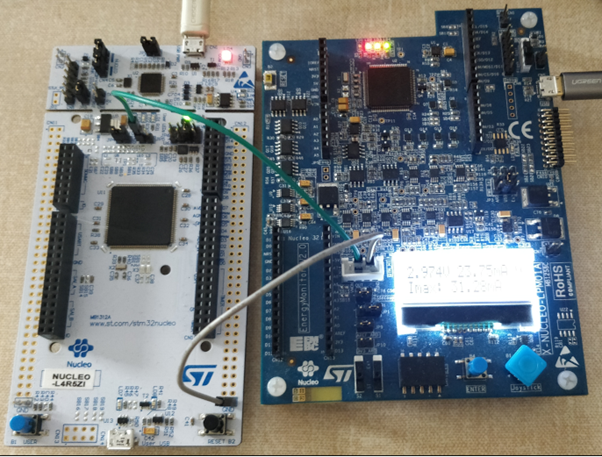
- Connect the power shield to the board: simply remove the IDD jumper and connect the out pin of the white connector of the power shield (3rd pin from the right) to the pin of the IDD connector connected to the STM32 (left pin on the Nucleo board) and connect the GND pin of the power shield to a GND pin of the Nucleo board.
- Power up the power shield through the USB port.
- Connect the Nucleo board as usual to the PC with a USB cable.
- Using the joystick, select the appropriate voltage. Measurements are to be done at 3 V (default) or 3.3 V to ensure UART communication to the STLink and then to the PC through Virtual Com port.
- For Ultra Low Power STM32 like the STM32L4R5ZI, current is below 50 mA and dynamic mode can be used (default mode).
- For high-performance STM32s such as the STM32H7, the current is between 50 mA and 200 mA, the static mode must be selected (use the joystick to select it).
- Press the enter button to power the STM32.
- As the STLink is powered separately, the STM32 firmware can be loaded as usual and VCom can be opened.
Controlled mode For STM32s that do not require more than 50 mA, the power shield can be used in controlled mode
- For controlled mode, download and install STM32CubeMonitor-Power.
- Follow the user manual instructions to connect and control the power shield.
- Cube Monitor Power allows average-value display/save/compute of the on a given window of the measured current over time.
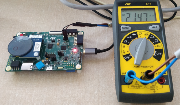
Alternatively, to the NUCLEO-LPM01A power shield, an ammeter can be used by removing the IDD jumper to connect it:
4.2. Inference time report
Once the STM32 board is connected to the PC through USB (USB PWR connector, not the User USB), a hyper terminal can be opened to get messages from the boards. The STM32 is identified by a COM port. Open a hyperterminal such as TeraTerm and configure the serial port configuration as follows:
- Port: the STM32 com port number
- Speed: 115200 bits/s
- Data: 8 bits
- Parity: none
- Stop bits: 1 bit
- Flow control: none
From board reset, the board reports the results of the average inference time :
#
# AI system performance measurement 5.2
#
Compiled with GCC 9.3.1
STM32 Runtime configuration...
 Device       : DevID:0x0470 (STM32L4Rxxx) RevID:0x1003
 Core Arch.   : M4 - FPU PRESENT and used
 HAL version  : 0x010d0000
 system clock : 120 MHz
 FLASH conf.  : ACR=0x00000605 - Prefetch=False $I/$D=(True,True) latency=5
 Calibration  : HAL_Delay(1)=1.002 ms

AI platform (API 1.1.0 - RUNTIME 7.0.0)
Discovering the network(s)...

Found network "network"
Creating the network "network"..
Initializing the network
Network informations...
 model name         : network
 model signature    : 7c2d7e42ad7cf646bfa1597f40fedd81
 model datetime     : Mon Aug  2 13:14:24 2021
 compile datetime   : Aug  2 2021 13:22:51
 runtime version    : 7.0.0
 tools version      : 7.0.0
 complexity         : 13597156 MACC
 c-nodes            : 31
 activations        : 67136 bytes (0x20003660)
 weights            : 478804 bytes (0x080105e0)
 inputs/outputs     : 1/1
  I[0]  u8, scale=0.007812, zero=128, 49152 bytes, shape=(128,128,3) (@0x20003dac)
  O[0]  u8, scale=0.003906, zero=0, 1001 bytes, shape=(1,1,1001) (@0x20003660)

Running PerfTest on "network" with random inputs (16 iterations)...
................

Results for "network", 16 inferences @120MHz/120MHz (complexity: 13597156 MACC)
 duration     : 427.337 ms (average)
 CPU cycles   : 51280470 (average)
 CPU Workload : 42% (duty cycle = 1s)
 cycles/MACC  : 3.77 (average for all layers)
 used stack   : 840 bytes
 used heap    : 0:0 0:0 (req:allocated,req:released) max=0 cur=0 (cfg=0)
 observer res : 520 bytes used from the heap (31 c-nodes)

 Inference time by c-node
  kernel  : 427.149ms (time passed in the c-kernel fcts)
  user    : 0.320ms (time passed in the user cb)

 c_id  type                id       time (ms)
 ---------------------------------------------------
 0     CONV2D              0         62.275  14.58 %
 1     CONV2D              1         41.909   9.81 %
 …
 30    NL                  30         0.133   0.03 %
 -------------------------------------------------
                                    427.149 ms

Running PerfTest on "network" with random inputs (16 iterations)...

Starting infinite power measurement loop
From the ”Starting infinite power measurement loop” message, the code loops on the inference processing and you can measure the power consumption then compute the energy per inference.
4.3. Measurement process
4.3.1. Measurement process when current is below 50 mA
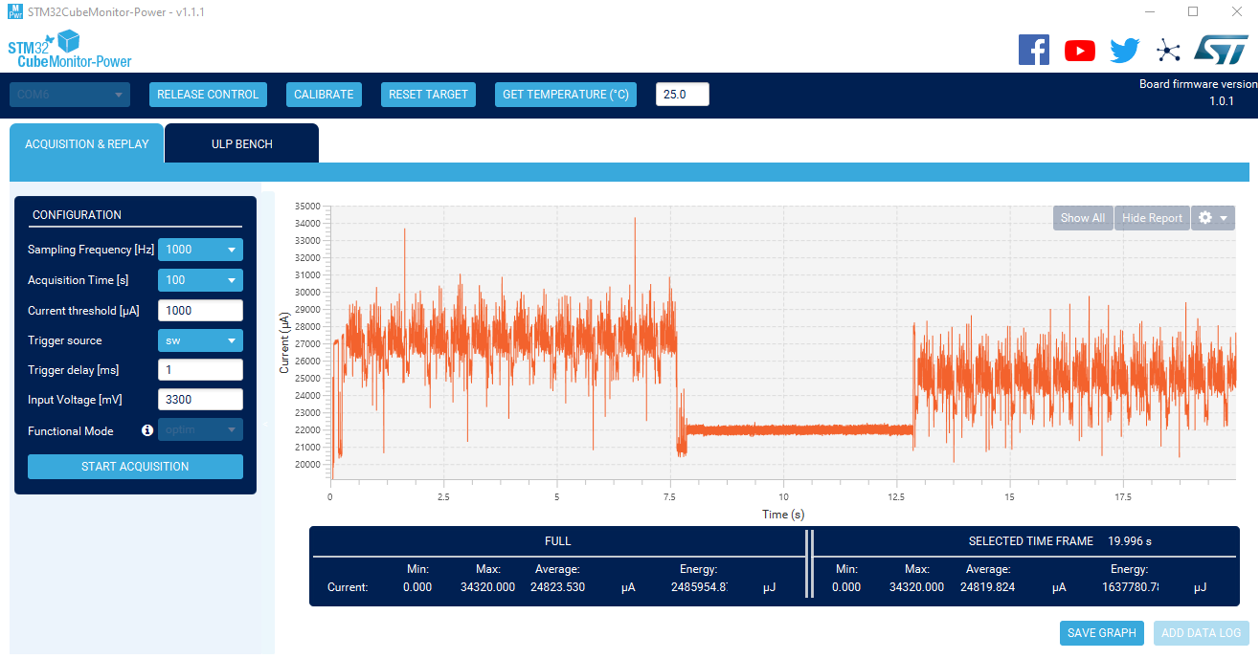
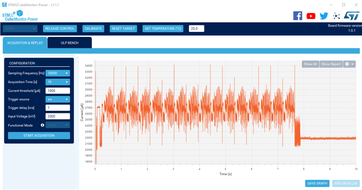
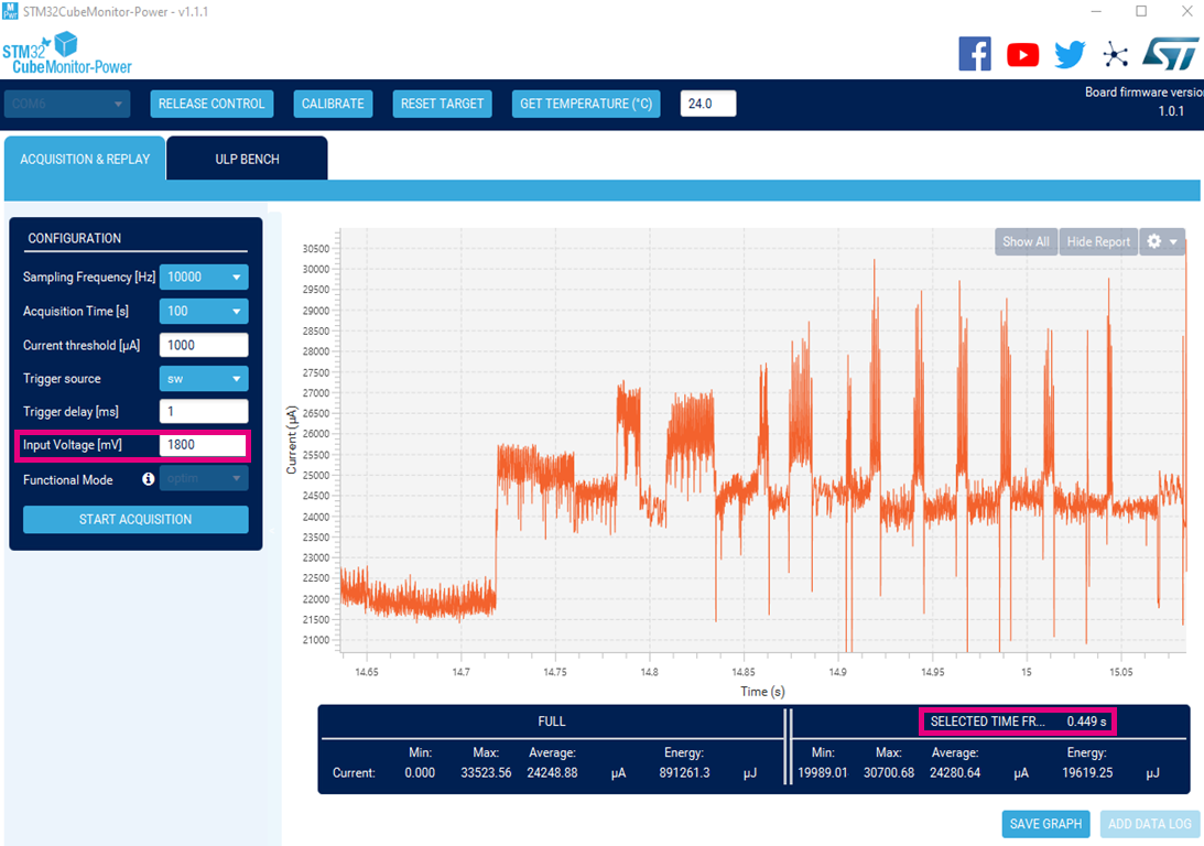
One measurement process method is to use the X-NUCLEO-LPM01A power shield in controlled mode with STM32CubeMonitor-Power. From STM32CubeMonitor-Power, take control of the power shield, set a high sampling frequency - typically 10000 Hz, a first acquisition period (for instance 10 s) and a input voltage of 3.3 V or 3 V. Then open a hyper terminal to get the log from the board and start the acquisition on STM32CubeMonitor-Power. Wait for the “Starting infinite power measurement loop” message from the board log.
From the board log, retrieve the average inference time computed on 16 inferences of the neural network. Then start another acquisition on a fixed period to cover several inference periods, typically 10 s, and click on “Show Report” to get the average current over the 10 s interval.
From the report on the UART you have the average inference time of t seconds, from the STM32CubeMonitor-Power you have the average current of i amperes for a given input voltage of u volts. The average energy is easily computed as (t x i x u) in joules.
4.3.2. Measurement process when current is above 50 mA
To get accurate measurements use of an advanced power/current/energy analyzer capable of providing accurate average current consumption on a given period is recommended. For a first estimation - if current is below 200 mA - you can use the X-NUCLEO-LPM01A power shield in “static” mode. Be sure to wait for the message “Starting infinite power measurement loop” from the board log. The power shield display then provides current static measures. You can then estimate the average current consumption.
Here are a couple of references for current measurement:
- The [Qoitec Otii Arc] power analyzer which is also providing power supply capability (as the the X-NUCLEO-LPM01A power shield).
- The [Joulescope JS110 https://www.joulescope.com/products/joulescope-precision-dc-energy-analyzer] plus a low-noise power supply.
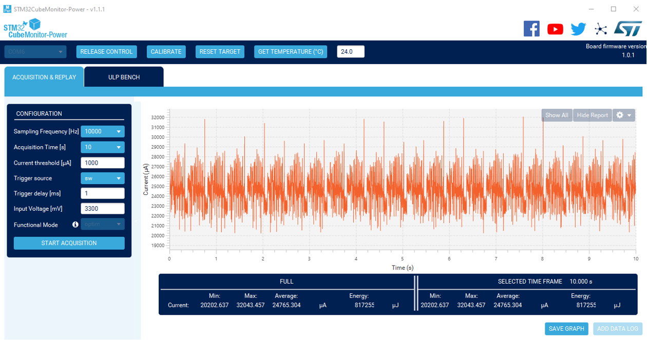
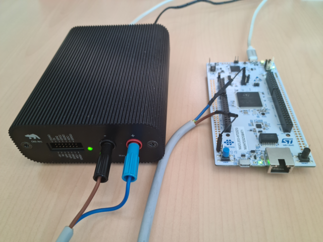
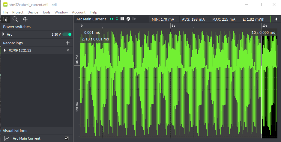
With the Qoitec Otii Arc, you can apply the same methodology as with the X-NUCLEO-LPM01A power shield using the free standard Otii software and using a 10 s analysis window. Hardware setup illustration:
Otii Arc current measurement window:
5. Power measurement at 1.8 V
The X-NUCLEO-LPM01A power shield can power the board at different voltages, typically 1.8 V, 3 V or 3.3 V, and when connected as described in the Board HW setup section directly supplies the STM32.
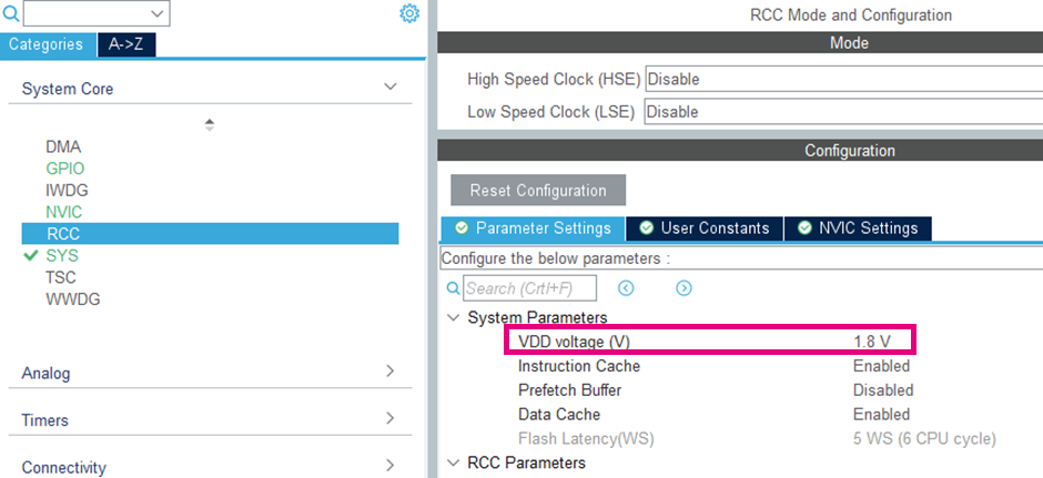
To make measurements at 1.8 V, be sure to modify the RCC/System parameter settings accordingly in the System Core category before generating the project. Some parameters such as the Flash latency is then automatically adapted if needed.
The STLink embedded in ST evaluation board is powered at 3.3 V. The STLink is used to program the STM32 and also to provide the Virtual Com capability. The STM32 is connected through a UART to the STLink, which is itself connected to the PC via USB, allowing communication between the STM32 and the PC on a given Com port. If the STM32 is powered at 1.8 V, the communication between the STLink and the PC, as well as the STM32 programming, are challenged. To avoid programming issues, load the firmware without the power shield connected, and hence with default board conditions at 3.3 V. The power shield can then be connected. It might for instance be the case that the STM32 log is not properly captured on the hyperterminal. In such cases, you can easily measure the inference time by means of the ST32CubeMonitor-Power tool (in cases where the current is below 50 mA). Perform current acquisition as in the 3.3 V, case but be sure to configure the input voltage at 1800 mV. In the established power measurement regime, the code loops infinitely on the inference. It then easy to identify the power pattern on the graphic and obtain the inference-time measurement. You can average over several windows if necessary. The inference time should be of the same order of magnitude as that at 3.3 V.
For currents above 50 mA, the same methodology can be applied using another advanced ammeter. With the X-NUCLEO-LPM01A power shield, you can use the inference time measured at 3.3 V as an estimation, then make the current measurements in static mode, setting the voltage to 1.8 V (in all other respects the methodology is the same as that used at 3.3 V).
Alternatively, to get the UART working at the right voltage, you can use an available UART instead of going through the STLink (you have to change the UART default settings defined automatically by STM32Cube.AI). You can then use USB TTL Serial Cable operating at 1.8 V as sold by [tps://ftdichip.com/products/ttl-232rg-vreg1v8-we FTDI Chip]. Alternatively, use a level-shifter board such as the 4-channel BSS138 devices, as sold by AdaFruit to connect to an STLink (from a Nucleo board or an external STLink). More information on alternative energy measurement setup can be found on the EEMBC GitHub at the following link: https://github.com/eembc/energyrunner#hardware-setup.
6. Important notes
6.1. Specific case of STM32H747 Discovery board
The STM32H747 has an internal SMPS, but this power supply option can only be used up to 400 MHz and with a specific HW configuration. At 480 MHz, the LDO option must be used. The STM32H747 is configured by default to be able to run on an SMPS, but it is therefore limited to 400 MHz. The board can be configured for 480 MHz but needs to be reconfigured with specific jumpers. Be careful also when configured for 480 MHz to use the appropriate SW configuration. Power efficiency is optimal in SMPS mode. When configuring the STM32H747 Discovery board in CubeMX, be sure to set the HCLK frequency to 400 MHz and that the Power Parameters SupplySource is set to PWR_DIRECT_SMPS_SUPPLY in the System Core / RCC panel.
6.2. External SMPS
Some boards such as the NUCLEO-L4R5ZI-P embed an external SMPS, however a specific initialization sequence is required to enable it. X-CUCE-AI does not enable this specific mode, so be careful that the SMPS is not enabled when following the tutorial above.
6.3. Power measurements
Note that power/energy measurements vary with temperature, the STM32 part measured, the measurement material and its setting. On a final application, the power consumption varies depending on the code, memory placement and even input data. Note that with the tutorial above, the input data are random but once in current measurement established regime they will not change and stay identical during the full sequence. Although the measurements vary from one trial to another, they should remain of the same order of magnitude.
7. STMicroelectronics references
See also:


