1. Introduction
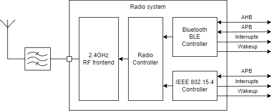
The STM32WB SoC is a dual-core, multi-protocol wireless microcontroller. STM32WB55 microcontrollers support the Bluetooth® 5 and IEEE 802.15.4 wireless standards. In the internal architecture, Bluetooth® Low Energy and 802.15.4 protocols share the same radio IP. At a specific moment, the radio IP is configured in either 802.15.4 or Bluetooth® Low Energy mode, but not both simultaneously.
| Radio peripheral |
|---|
2. Dynamic mode use case
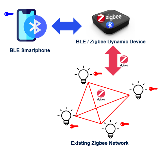
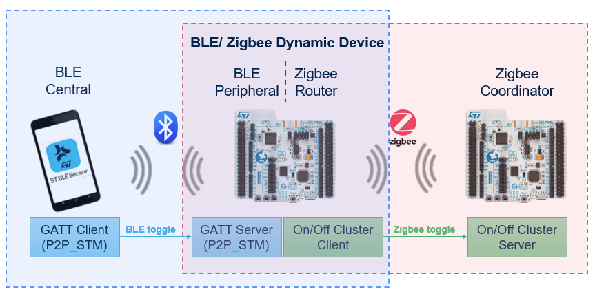
A typical use case is an on/off switch light to control the lighting in a room or a group of rooms. The mobile app would likely use Bluetooth® Low Energy to communicate with the central hub or controller, while the LED light would use Zigbee to communicate with the hub or controller.
This use case requires a dynamic mode, with the ability to control its Zigbee network through a Bluetooth® Low Energy connection, and thus requires a device that's able to handle both protocols at a time, using a radio time-sharing scheme.
| Dynamic mode use case |
|---|
3. Concurrency architecture
3.1. RTSM description
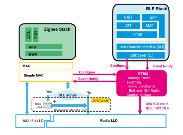
The radio time-sharing manager (RTSM) implementation enables radio switching between Bluetooth® Low Energy and 802.15.4, which allows the Bluetooth® Low Energy and Zigbee stacks to operate in parallel on the same radio.
- On the Zigbee side, the RTSM is integrated at SimpleMAC level, which interfaces between the MAC layer and the 802.15.4/radio LLD.
- On the Bluetooth® Low Energy side, the RTSM is integrated between the link layer and the radio LLD.
| RTSM block diagram |
|---|
For more information, refer to the application note Getting started with Dynamic-concurrent mode BLE / Zigbee® on STM32WB Series microcontrollers[1] (AN5613).
3.2. Bluetooth® Low Energy and Zigbee stack behavior
Despite the radio switching between Bluetooth® Low Energy and Zigbee, both stacks are unaware of the switching mechanism and operate under the assumption that the radio is exclusively dedicated to them.
Due to its tighter time constraints, Bluetooth® Low Energy requires higher priority on radio access than 802.15.4-based protocols like Zigbee.
3.2.1. Bluetooth® Low Energy stack
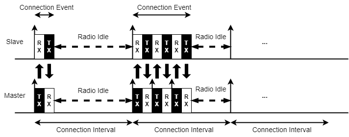
On the Bluetooth® Low Energy side, the connection event must be scheduled exactly at the expected connection interval (CI). The RTSM takes care of this precise timing.
- Connection interval: time between two connection events (from 7.5 ms to 4 s).
- Connection events: consecutive Rx/Tx switch between controller and target in a connection interval.
- Radio idle slot: assigned by the RTSM to 802.15.4, allowing the Zigbee operation.
| Bluetooth® Low Energy connection events and connection intervals |
|---|
3.2.2. Zigbee stack
On the Zigbee side, Tx and Rx occur at any time depending on the local and remote Zigbee device needs.
- For Zigbee/MAC Tx requests:
- If the radio is granted to 802.15.4, it transmits as usual.
- If the radio is granted to Bluetooth® Low Energy, all radio commands (including Tx) are stored in the cmd_pipe.
- When the radio is granted back to 802.15.4, all pending commands (including Tx) are sent.
- For Zigbee/MAC Rx events:
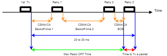
- All Rx events are managed under Rx interrupt. Such an interrupt is disabled while the radio is in Bluetooth® Low Energy mode. With the CSMA/CA retry mechanism (up to three retries), these Rx events are rescheduled a few milliseconds later.
- Internal investigations have shown that the maximum time without radio (assigned to Bluetooth® Low Energy) must be less than 16 ms to prevent packet loss.
| Zigbee Rx/Tx behavior |
|---|
4. STM32WB dynamic application design
In the STM32CubeWB MCU Package[2], several dynamic-mode applications are available:
- Bluetooth® Low Energy/Zigbee dynamic application
- Bluetooth® Low Energy/Zigbee dynamic SED application
- Bluetooth® Low Energy/Zigbee dynamic Bluetooth® Low Energy throughput application
- Bluetooth® Low Energy/Zigbee dynamic NVM application
This wiki page focuses on a Bluetooth® Low Energy/Zigbee dynamic application.
4.1. Bluetooth® Low Energy/Zigbee dynamic firmware supported
The dynamic-mode firmware includes both Bluetooth® Low Energy and Zigbee stacks:
- The Bluetooth® Low Energy stack is Bluetooth® Low Energy 5.0 certified.
- Two flavors of the Zigbee® stacks are supported on the STM32WB series devices: FFD (full-feature device) and RFD (reduced-feature device). These stacks are Zigbee PRO 2017 (revision 22) certified and detailed in the table below.
| Stacks supported | Firmware associated |
|---|---|
| Zigbee FFD + Bluetooth® Low Energy 5.0 | stm32wb5x_BLE_ZigBee_FFD_dynamic_fw.bin |
| Zigbee RFD + Bluetooth® Low Energy 5.0 | stm32wb5x_BLE_ZigBee_RFD_dynamic_fw.bin |
4.2. Bluetooth® Low Energy/Zigbee dynamic application framework
All projects are built using the same framework. The main application features are defined in:
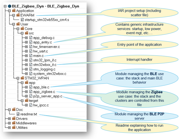
Projects/Board_X/Applications/BLE_ZigBee/BLE_ZigBee_Dyn/STM32_WPAN/App
| Bluetooth® Low Energy/Zigbee dynamic application |
|---|
4.3. Bluetooth® Low Energy/Zigbee dynamic application
This application illustrates the simultaneous Bluetooth® Low Energy and Zigbee connections on the same device, with a Bluetooth® Low Energy P2P app execution and a Zigbee toggle on/off application running simultaneously on the same device.
This application requires having the STM32WB5x_BLE_Zigbee_FFD_dynamic_fw.bin binary programmed on the Arm® Cortex®-M0 wireless coprocessor.
| Bluetooth® Low Energy/Zigbee dynamic-mode application demo |
|---|
4.3.1. Hardware requirements
- One STM32WB55xx-Nucleo board in Bluetooth® Low Energy/Zigbee Dynamic-concurrent mode.
- One or more STM32WB55xx-Nucleo boards for creating a Zigbee network (refer to the readme file of the example Zigbee_OnOff_Server_Coord and Zigbee_OnOff_Client_Router for more details on how to use it).
- One STM32WB55xx-Nucleo board running a BLE_p2pClient application, OR a smartphone (Android/IOS) running the ST BLE Sensor Classic phone application (available on Apple Store[3] and Google Play[4].
4.3.2. Application setup
Refer to the previous image for more details about device roles.
- The first step is to rebuild projects and load the images onto the STM32WB boards.
- By default, the Zigbee/Bluetooth® Low Energy board starts with both Bluetooth® Low Energy and Zigbee modes activated.
- The Zigbee/Bluetooth® Low Energy device (P2P Server) starts Bluetooth® Low Energy advertising (green LED toggling) and simultaneously starts to join the Zigbee Network. The blue LED turns on when Zigbee has successfully joined the network.
- The Zigbee router sends a Zigbee on/off toggle to the Zigbee coordinator every second. The red LED toggles on the coordinator.
- The Bluetooth® Low Energy connection starts as follows, depending on whether the Bluetooth® Low Energy device is a smartphone or a third Nucleo board:
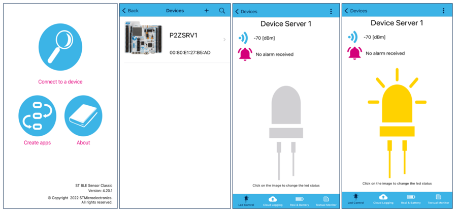
- If using a smartphone, open the ST BLE Sensor Classic App (smartphone application) and click Connect to a device. The application now scans for available boards. Connect to the P2P server by selecting the P2ZSRV1 entry.
Once connected, the application starts to search for the P2P services and characteristics, and displays the LED control service.
Pressing the LED image on the application turns the red LED on the Zigbee/Bluetooth® Low Energy device on or off .
- If using a third Nucleo board (running a BLE_p2pClient application), start scanning by pressing the SW1 button.
The blue LED lights up.
When the scan has finished, the third Nucleo board connects to the P2P server in Zigbee/Bluetooth® Low Energy dynamic mode, and sends a Bluetooth® Low Energy toggle when pressing SW1.
As a result, the red LED toggles on the Zigbee/Bluetooth® Low Energy device at each SW1 button press on the Bluetooth® Low Energy board.
- If using a smartphone, open the ST BLE Sensor Classic App (smartphone application) and click Connect to a device. The application now scans for available boards. Connect to the P2P server by selecting the P2ZSRV1 entry.
5. Acronyms and definitions
| Term | Definition |
|---|---|
| GATT | Generic attribute profile |
| P2P | Peer-to-peer |
| FFD | Full-feature device |
| RFD | Reduced-feature device |
| RTSM | Radio time-sharing manager |
6. References
