The FP-AI-NANOEDG1 function pack helps users to jump-start the development and implementation of condition monitoring applications, powered by NanoEdge™ AI Studio, a solution from Cartesiam.
NanoEdge™ AI Studio simplifies the creation of autonomous machine learning libraries, which are able to not just run the inference but also training on the edge. It facilitates the integration of predictive maintenance capabilities as well as the security and detection with sensor patterns self-learning and self-understanding, exempting users from special skills in mathematics, machine learning, data science, or creation and training of the neural networks.
FP-AI-NANOEDG1 covers the entire development cycle for a condition monitoring application, starting from the data set acquisition to the integration of NanoEdge™ AI Studio generated libraries on a physical sensor-node. It runs the inference in real-time on an STM32L4R9ZI ultra-low-power microcontroller (Arm® Cortex®-M4 at 120 MHz with 2 Mbytes of Flash memory and 640 Kbytes of SRAM), taking physical sensor data as input. FP-AI-NANOEDG1 implements a wired interactive command-line interface (CLI) to configure the node, record data, and manage learning and detection phases. However, all these operations can also be performed in a standalone battery-operated mode through the user button, without having the console. In addition to this V2.0 of FP-AI-NANOEDG1 comes with a mode that is completely independent and can be simply configured through some configuration files. This mode provides the user with the capability to run different execution phases automatically when the sensor mode is powered or a reset is performed. The NanoEdge™ library generation itself is out of the scope of this function pack and must be carried out using NanoEdge™ AI Studio.
The rest of the article describes the contents of the FP-AI-NANOEDG1 function pack and details of the different steps to build condition monitoring applications on the STEVAL-STWINKT1B based on vibration data.
NOTE: STEVAL-STWINKT1B is a new revision of the STEVAL-STWINKT1 board, contact your distributors in case of doubt.
1. General information
The FP-AI-NANOEDG1 function pack runs on STM32L4+ microcontrollers based on Arm® cores.
1.1. Feature overview
The FP-AI-NANOEDG1 function pack features:
- Complete firmware to program an STM32L4+ sensor node for condition monitoring and predictive maintenance applications
- Stub for replacement with a Cartesiam Machine Learning library generated using the NanoEdge™ AI Studio for the desired AI application
- Configuration and acquisition of STMicroelectronics (IIS3DWB) 3-axis digital vibration sensor, and (ISM330DHCX) 6-axis digital accelerometer and gyroscope iNEMO inertial measurement unit (IMU) with machine learning core
- Data logging on a microSD™ card
- Embedded file system utilities
- Interactive command-line interface (CLI) for:
- - Node and sensor configuration
- - Data logging
- - Management of learning and detection phase of the NanoEdge™ library
- An extended configurable autonomous mode, controlled by the user button and the configuration files stored in the microSD™ card
- Easy portability across STM32 microcontrollers by means of the STM32Cube ecosystem
- Free and user-friendly license terms
1.2. Software architecture
The STM32Cube function packs leverage the modularity and interoperability of STM32 Nucleo and expansion boards running STM32Cube MCU Packages and Expansion Packages to create functional examples representing some of the most common use cases in certain applications. The function packs are designed to fully exploit the underlying STM32 ODE hardware and software components to best satisfy the final user application requirements.
Function packs may include additional libraries and frameworks, not present in the original STM32Cube Expansion Packages, which enable new functions and create more targeted and usable systems for developers.
STM32Cube ecosystem includes:
- A set of user-friendly software development tools to cover project development from the conception to the realization, among which are:
- STM32CubeMX, a graphical software configuration tool that allows the automatic generation of C initialization code using graphical wizards
- STM32CubeIDE, an all-in-one development tool with peripheral configuration, code generation, code compilation, and debug features
- STM32CubeProgrammer (STM32CubeProg), a programming tool available in graphical and command-line versions
- STM32CubeMonitor (STM32CubeMonitor, STM32CubeMonPwr, STM32CubeMonRF, STM32CubeMonUCPD) powerful monitoring tools to fine-tune the behavior and performance of STM32 applications in real-time
- STM32Cube MCU & MPU Packages, comprehensive embedded-software platforms specific to each microcontroller and microprocessor series (such as STM32CubeL4 for the STM32L4+ Series), which include:
- STM32Cube hardware abstraction layer (HAL), ensuring maximized portability across the STM32 portfolio
- STM32Cube low-layer APIs, ensuring the best performance and footprints with a high degree of user control over the HW
- A consistent set of middleware components such as FreeRTOS™, USB Device, USB PD, FAT file system, Touch library, Trusted Firmware (TF-M), mbedTLS, Parson, and mbed-crypto
- All embedded software utilities with full sets of peripheral and applicative examples
- STM32Cube Expansion Packages, which contain embedded software components that complement the functionalities of the STM32Cube MCU & MPU Packages with:
- Middleware extensions and applicative layers
- Examples running on some specific STMicroelectronics development boards
To access and use the sensor expansion board, the application software uses:
- STM32Cube hardware abstraction layer (HAL): provides a simple, generic, and multi-instance set of generic and extension APIs (application programming interfaces) to interact with the upper layer applications, libraries, and stacks. It is directly based on a generic architecture and allows the layers that are built on it, such as the middleware layer, to implement their functions without requiring the specific hardware configuration for a given microcontroller unit (MCU). This structure improves library code reusability and guarantees easy portability across other devices.
- Board support package (BSP) layer: supports the peripherals on the STM32 Nucleo boards.
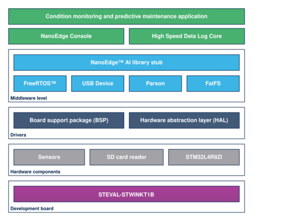
The top-level architecture of the FP-AI-NANOEDG1 function pack is shown in the following figure.
1.3. Development flow
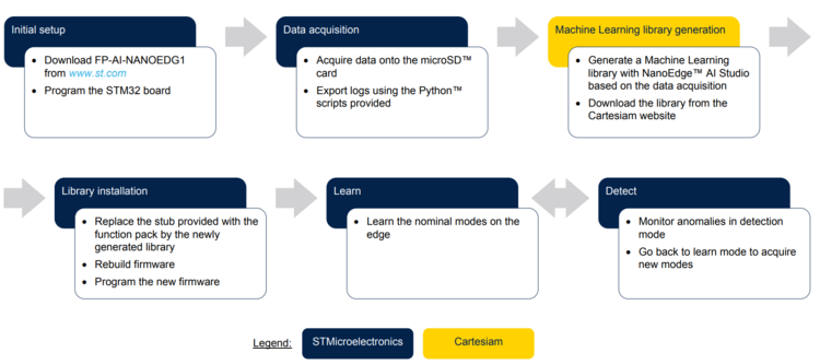
FP-AI-NANOEDG1 does not embed any Machine Learning technology but it facilitates for it. It provides all the means to help the generation of the Machine Learning algorithm by NanoEdge™ AI Studio and embeds it easily in the STEVAL-STWINKT1B evaluation kit in a practical way. The following figure provides six steps of the suggested flow.
1.4. Folder structure
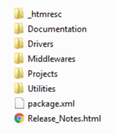
The figure above shows the contents of the function pack folder. The contents of each of these subfolders are as follows:
- Documentation: contains a compiled
.chmfile generated from the source code, which details the software components and APIs. - Drivers: contains the HAL drivers, the board-specific part drivers for each supported board or hardware platform (including the onboard components), and the CMSIS vendor-independent hardware abstraction layer for the Cortex®-M processors.
- Middlewares: contains libraries and protocols for USB Device library, generic FAT file system module (FatFS), FreeRTOS™ real-time OS, Parson a JSON browser, and the NanoEdge™ AI library stub.
- Projects: contains a sample application software, which can be used to program the sensor-board for collecting data from motion sensors onto the microSDTM card and manage the learning and detection phases of Cartesiam Machine Learning solution provided for the STEVAL-STWINKT1B platforms through the STM32CubeIDE development environment.
- Utilities: contains python scripts and sample datasets. These python scripts can be used to parse and prepare the data logged from the FP-AI-NANOEDG1 for the Cartesiam library generation. The Jupyter notebook contains an example of the full pipeline for preparing the datalogs generated by the function pack datalogger to NanoEdge™ AI Studio compliant
.csvfiles, which are required to generate the Machine Learning libraries from NanoEdge™ AI Studio.
1.5. Terms and definitions
| Acronym | Definition. |
|---|---|
| API | Application programming interface |
| BSP | Board support package |
| CLI | Command line interface |
| FP | Function pack |
| GUI | Graphical user interface |
| HAL | Hardware abstraction layer |
| LCD | Liquid-crystal display |
| MCU | Microcontroller unit |
| ML | Machine learning |
| ODE | Open development environment |
1.6. References
| References | Description | Source |
|---|---|---|
| [1] | Cartesiam website | cartesiam.ai |
| [2] | STEVAL-STWINKT1B | STWINKT1B |
1.7. Prerequisites
- One of the following IDEs must be installed:
- STMicroelectronics - STM32CubeIDE version 1.4.2
- IAR Embedded Workbench for Arm (EWARM) toolchain V8.50.5 or later
- RealView Microcontroller Development Kit (MDK-ARM) toolchain V5.31
- FP-AI-NANOEDG1 can be deployed on the following operating systems:
- Windows® 10
- Ubuntu® 18.4 and Ubuntu® 16.4 (or derived)
- macOS® (x64)
Note: Ubuntu® is a registered trademark of Canonical Ltd. macOS® is a trademark of Apple Inc. registered in the U.S. and other countries.
1.8. Licenses
FP-AI-NANOEDG1 is delivered under the Mix Ultimate Liberty+OSS+3rd-party V1 software license agreement (SLA0048).
The software components provided in this package come with different license schemes as shown in the table below.
| Software component | Copyright | License |
|---|---|---|
| Arm® Cortex®-M CMSIS | Arm Limited | Apache License 2.0 |
| FreeRTOS™ | Amazon.com, Inc. or its affiiates | MIT |
| STM32L4xxx_HAL_Driver | STMicroelectronics | BSD-3-Clause |
| Board support package (BSP) | STMicroelectronics | BSD-3-Clause |
| STM32L4xx CMSIS | Arm Limited - STMicroelectronics | Apache License 2.0 |
| FatFS | ChaN | BSD-3-Clause |
| Parson | Krzysztof Gabis | MIT |
| Applications | STMicroelectronics | Proprietary |
| Python TM scripts | STMicroelectronics | BSD-3-Clause |
| Dataset | STMicroelectronics | Proprietary |
| NanoEdge Console application | STMicroelectronics | Proprietary |
| High-Speed Data Log Core application | STMicroelectronics | Proprietary |
2. Hardware and firmware setup
2.1. Presentation of the Target STM32 board
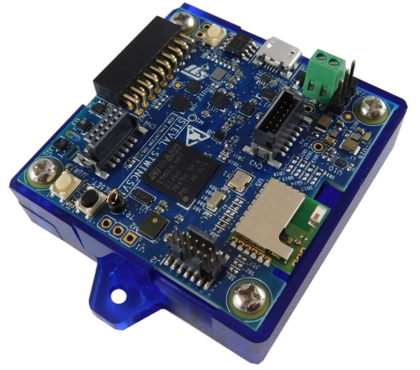
The STWIN SensorTile wireless industrial node (STEVAL-STWINKT1B) is a development kit and reference design that simplifies the prototyping and testing of advanced industrial IoT applications such as condition monitoring and predictive maintenance. It is powered with Ultra-low-power Arm® Cortex®-M4 MCU at 120 MHz with FPU, 2048 kbytes Flash memory (STM32L4R9). Other than this, STWIN SensorTile is equipped with a microSD™ card slot for standalone data logging applications, a wireless BLE4.2 (on-board) and Wi-Fi (with STEVAL-STWINWFV1 expansion board), and wired RS485 and USB OTG connectivity, as well as Brand protection secure solution with STSAFE-A110. In terms of sensor, STWIN SensorTile is equipped with a wide range of industrial IoT sensors including:
- an ultra-wide bandwidth (up to 6 kHz), low-noise, 3-axis digital vibration sensor (IIS3DWB)
- a 6-axis digital accelerometer and gyroscope iNEMO inertial measurement unit (IMU) with machine learning (ISM330DHCX)
- an ultra-low-power high-performance MEMS motion sensor (IIS2DH)
- an ultra-low-power 3-axis magnetometer (IIS2MDC)
- a digital absolute pressure sensor (LPS22HH)
- a relative humidity and temperature sensor (HTS221)
- a low-voltage digital local temperature sensor (STTS751)
- an industrial-grade digital MEMS microphone (IMP34DT05), and
- a wideband analog MEMS microphone (MP23ABS1)
Other attractive features include:
- – a Li-Po battery 480 mAh to enable standalone working mode
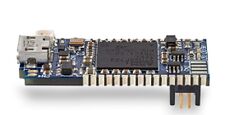
- – STLINK-V3MINI debugger with programming cable to flash the board
- – a Plastic box for ease of placing and planting the SensorTile on the machines for condition monitoring. For further details, the users are advised to visit this link
2.2. Connect hardware
To start using FP-AI-NANOEDG1, the user needs:
- A personal computer with one of the supported operating systems, (Windows® 10, Ubuntu® 18.4 and Ubuntu® 16.4, or macOS® x64)
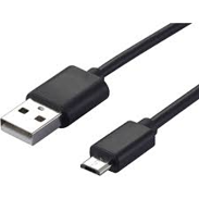
- One USB cable to connect the sensor node to the PC through STLINK-V3MINI
- An STEVAL-STWINKT1B board
- One microSD™ card formatted as FAT32 FileSystem.
Follow the next two steps to connect hardware:
- Connect the STM32 sensor board to the computer through the STLINK with the help of a USB micro cable. This connection will be used to program the STM32 MCU.
- Connect another micro USB cable to the STWIN USB connector. This connection will be used for the communication between the CLI console and the sensor node.
- Insert the microSD™ card into the dedicated slot to store the data from the datalogger.
Note: Before connecting the sensor board to a Windows® PC through USB, the user needs to install a driver for the ST-LINK-V3E (not required for Windows 10®). This software can be found on the ST website. The power source for the board can either be a battery for standalone operations or a USB cable connection to the USART interface.
2.3. Program firmware into the STM32 microcontroller
This section explains how to select binary firmware and program it into the STM32 microcontroller. Binary firmware is delivered as part of the FP-AI-NANOEDG1 function pack. It is located in the FP-AI-NANOEDG1_V2.0.0/Projects/STM32L4R9ZI-STWIN/Applications/NanoEdgeConsole/Binary folder. When the STM32 board and PC are connected through the USB cable on the STLINK-V3E connector, the related drive is available on the PC. Drag and drop the chosen firmware into that drive. Wait a few seconds for the firmware file to disappear from the file manager: this indicates that firmware is programmed into the STM32 microcontroller.
2.4. Using the serial console
A serial console is used to interact with the host board (Virtual COM port over USB). With the Windows® operating system, the use of the Tera Term software is recommended. Following are the steps to configure the Tera Term console for CLI over a serial connection.
2.4.1. Set the serial terminal configuration
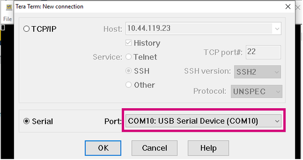
Start Tera Term, select the proper connection (featuring the STMicroelectronics name),
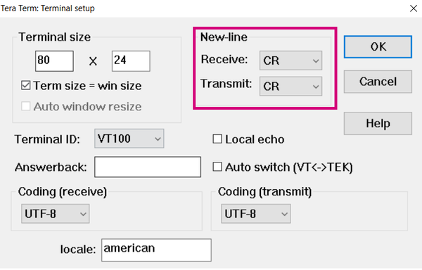
Set the parameters:
- Terminal
- [New line]:
- [Receive]: CR
- [Transmit]: CR
- [New line]:
- Serial
- The interactive console can be used with the default values.
2.4.2. Start FP-AI-NANOEDG1 firmware
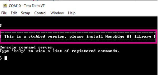
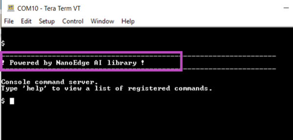
Restart the board by pressing the RESET button. The following welcome screen is displayed on the terminal.
From this point, start entering the commands directly or type help to get the list of available commands along with their usage guidelines.
Note: The provided firmware is generated with a stub in place of the current library. The user must generate the library with the help of the NanoEdge™ AI Studio, replace the stub with it, and rebuild firmware. These steps are detailed in the following sections.
3. Autonomous and button-operated modes
This section provides details of the extended autonomous mode for FP-AI-NANOEDG1. The purpose of the extended mode is to enable the users to operate the FP-AI-NANOEDG1 on STWIN even in the absence of the CLI console.
In autonomous mode, the sensor node is controlled through the user button instead of the interactive CLI console. The default values for node parameters and settings for the operations during auto-mode are provided in the FW. Based on these configurations different modes (learn, detect, and datalog) can be started and stopped through the user-button on the node. If the user wants to change these settings, then the default parameters and configurations can be overridden by providing configuration json files onto the microSD™ card inserted on the node.
Other than this button-operated mode, the autonomous mode is also equipped with a special mode, we call “auto mode”. The auto-mode can be initiated automatically, at the device power-up stage or whenever a reset is performed. In this mode, the user can choose to have one or even a chain of modes/commands (up to ten commands) to run in a sequence as a list of execution steps. For example, these commands could be learning the nominal mode for a given duration and then start the detection mode for anomaly detection. Other than this, this mode can also be used to start the datalog operations or even to pause all the executions for a specific period of time by putting the sensor node in the "idle" phase.
The following sections provide brief details on different blocks of these extended autonomous modes.
3.1. Interaction with user
As mentioned before, the auto-mode can work even when no connectivity (wired or wireless) available, although it also works as a button-operated mode when the console is available and is fully compatible and consistent with the current definition of the serial console and its Command Line Interface (CLI). The supporting hardware for this version of the function-pack (STWIN) is fitted with three buttons:
- User Button, the only SW usable,
- Reset Button, connected to STM32 MCU reset pin,
- Power Button connected to power management,
and three LEDs:
- LED_1 (green), controlled by Software,
- LED_2 (orange), controlled by Software,
- LED_C (red), controlled by Hardware, indicates charging status when powered through a USB cable.
So, the basic user interaction for button-operated operations is to be done through two buttons (user and reset) and two LEDs (Green and Orange). Following we provide details on how these resources are allocated to show the users what execution phases are active or to report the status of the sensor-node.
3.1.1. LED Allocation
In the function pack four execution phases exist:
- idle: the system waits for a specified amount of time.
- datalog: sensor(s) output data are streamed onto an SD card.
- learn: all data coming from the sensor(s) are passed to the NanoEdge AI library to train the model.
- detect: all data coming from the sensor(s) are passed to the NanoEdge AI library to detect anomalies.
At any given time, the user needs to be aware of the current active execution phase. We also need to report the outcome of the detection when the detect execution phase is active, telling the user if an anomaly has been detected. In addition, if a fatal error occurs and consequently the FW has stopped, the user needs to be notified, either to debug or to reset the node.
In total, we need the interaction mechanism to code six different states with the two available LEDs, so we need at least three patterns in addition to the traditional On-OFF options. At any given time the LED can be in one of the following states:
| Pattern | Description |
|---|---|
| OFF | the LED is always OFF |
| ON | the LED is always ON |
| BLINK | the LED alternates ON and OFF periods of equal duration (400 ms) |
| BLINK_SHORT | the LED alternates short (200 ms) ON periods with a short OFF period (200 ms) |
| BLINK_LONG | the LED alternates long (800 ms) ON periods with a long OFF period (800 ms) |
These patterns of each of the LEDs indicate the state of the sensor-node. Following table describes the state of the sensor-node for any of the patterns:
| Pattern | Green | Orange |
|---|---|---|
| OFF | Power OFF | |
| ON | idle | System error |
| BLINK | Data logging | MicroSD™ card missing |
| BLINK_SHORT | Detecting, no anomaly | Anomaly detected |
| BLINK_LONG | Learning, status OK | Learning, status FAILED |
3.1.2. Button Allocation
In the extended autonomous mode, the user can trigger any of the four execution phases or a special mode called the auto mode. The available modes are:
- idle: the system waits for a specified amount of time.
- datalog: sensor(s) output data is streamed onto an SD card.
- learn: all data coming from the sensor are passed to the NanoEdge AI library to train the model.
- detect: all data coming from the sensor are passed to the NanoEdge AI library to detect anomalies.
- auto mode: a succession of predefined execution phases.
For triggering these phases the FP-AI-NANOEDG1 is equipped with the support of the user button. In the STEVAL-STWINKT1B sensor-node, there are two software usable buttons:
- The user button: This button is fully programmable and is under the control of the application developer.
- The reset button: This button is used to reset the sensor-node and is connected to the hardware reset pin, thus is used to control the software reset.
In order to control the executions phases, we need to define and detect at least three different button press modes of the user button. The reset button is used to trigger the auto-mode at the reset or power-up mode(if configured through execution_config.json file).
Following are the types of the press available for the user button:
| Button Press | Description |
|---|---|
| SHORT_PRESS | The button is pressed for less than (200 ms) and released |
| LONG_PRESS | The button is pressed for more than (200 ms) and released |
| DOUBLE_PRESS | A succession of two SHORT_PRESS in less than (500 ms) |
| ANY_PRESS | The button is pressed and released (overlaps with the three other modes) |
In the table below a mapping for this different kind of button press patterns is provided:
| Current Phase | Action | Next Phase |
|---|---|---|
| Idle | SHORT_PRESS | detect |
| LONG_PRESS | learn | |
| DOUBLE_PRESS | datalog | |
| RESET | auto-mode if configured or idle | |
| learn, detect or datalog or auto-mode | ANY_PRESS | idle |
| RESET | auto-mode if configured or idle. |
3.2. Configuration
When the sensor-node is being operated from the interactive console, the users can configure the parameters of the sensors on the node as well as the parameters of different execution phases. In the absence of the console, the user can either use the default values for these parameters provided in the firmware, or FP-AI-NANOEDG1 also provides the users with the capability of override the default parameters through the configuration files. The json configuration files are to be placed in the root path of the microSD™ card. There are two configuration files that are used for this purpose. These configuration files are
- DeviceConfig.json : This configuration file contains the configuration parameters for sensors, such as the
fullScale,activeStatus, andODR(output data rate) of the sensors, andenablestatus. - execution_config.json: This configuration file contains the information about the executions phases when the sensor node is being operated in the autonomous mode, such that
timer(time to run an execution phase),signals(number of signals to be used in the learn or detect phases) and many more.
- DeviceConfig.json : This configuration file contains the configuration parameters for sensors, such as the
The following sections provide brief details along with simple example files for these two.
3.2.1. execution_config.json
execution_config.json is used to configure any execution context and phases as well as it provides the auto-mode activation at reset and its definition.
Here is the definition of different parameters that can be configured in this file:
- info: gives the definition of auto-mode as well as each execution context, any field present overrides the FW defaults.
- version: is the revision of the specification.
- auto_mode: if true, auto mode will start after reset and node initialization.
- execution_plan: is the sequence of maximum ten execution steps.
- start_delay_ms: indicates the initial delay in milliseconds applied after reset and before the first execution phase starts when auto mode is selected.
- phases_iteration: gives the number of times the execution_plan is executed, zero indicates an infinite loop.
- phase steps execution context settings.
- learn:
- - timer_ms: specifies the duration in ms of the execution phase. Zero indicates an infinite time.
- - signals: specifies the number of signals to be analyzed. Zero indicates an infinite value for signals.
- detect:
- - timer_ms: specifies the duration in ms of the execution phase. Zero indicates an infinite time.
- - signals: specifies the number of signals to be analyzed. Zero indicates an infinite value for signals.
- - threshold: specifies a value used to identify a signal as normal or abnormal.
- - sensitivity: specifies the sensitivity value for the NanoEdge AI library.
- datalog:
- - timer_ms: specifies the duration in ms of the execution phase. Zero indicates an infinite time.
- idle:
- - timer_ms: specifies the duration in ms of the execution phase. Zero indicates an infinite time.
- learn:
- info: gives the definition of auto-mode as well as each execution context, any field present overrides the FW defaults.
3.2.1.1. default example
If no microSD™ card is preset, or If no valid file on the root of the file system of the microSD™ card can be found, then all the FW defaults are applied. The default configuration for the auto mode is equivalent to the following execution_config.json example file:
{
	"info": {
		"version": "1.0",
		"auto_mode": false,
		"phases_iteration": 0,
		"start_delay_ms": 0,
		"execution_plan": [
			"idle"
		],
		"learn": {
			"signals": 0,
			"timer_ms": 0
		},
		"detect": {
			"signals": 0,
			"timer_ms": 0,
			"threshold": 90,
			"sensitivity": 1.0
		},
		"datalog": {
			"timer_ms": 0
		},
		"idle": {
			"timer_ms": 1000
		}
	}
}
3.2.2. DeviceConfig.json
The DeviceConfig.json file contains the parameters for the sensor-node and sensor-configurations. These parameters include:
- UUIDAcquisition: Unique identifier of acquisition (control and data files in folder)
- JSONVersion: version of current DeviceConfig.json file.
- Device: Datalogging HW and FW setup for current Acquisition
- deviceInfo: Board-level info
- Sensor: an array of sensors, each containing parameters, and configurations for a given sensor. Here following are the sample configuration parameters for a sample sensor:
- id: identifier of the sensor
- name: name or part number of the sensor
- sensorDescriptor: description of the sensor parameters
- subSensorDescriptor: an array of all sub-sensors in the sensor containing the configurations for each of the sub-sensors. Each element of the array contains the following parameters:
- id : identifier for the sub-sensor
- sensorType: type of the subsensor, for example
"ACC"for accelerometer - dimensions: number of dimensions of the data produced by the subsensor
- dimensionsLabel: a string array of
length = dimensionscontaining the labels of each sensor - unit : unit of the measure for the sensor
- dataType : type of the output sensor produce
- FS : an array of values available to be used as fullscale. This value controls the sensitivity of the sensor to measure small changes
- ODR : an array of the values that can be used as the output data sampling rates\
- samplesPerTs : minimum and maximum value of the samples before inserting a new time stamp. This option is used in the case of a time-stamped data acquisition is required. :*:*:* sensorStatus : the current or used values for the sensor and sub-sensor parameters
- subSensorStatus : an array for the parameter values for all the sub-sensors, each element contains:
- ODR : the set output data rate for the subsensor
- ODRMeasured: the current data rate with which the data is recorded, (this can differ from the requested data rate by +-10%)
- initialOffset : offset in the sensor values
- FS : value of the full scale used in the data acquisition
- sensitivity: sensitivity of the sensor
- isActive: a boolean to tell if the sub-sensor was active or not during the acquisition
- samplesPerTs: after how many samples a new timestamp is added
- tagConfig: data tagging labels configuration for current acquisition. This information is used for tagging the data during the data logging. The tags to the data acquisitions can be added using soft or hard tagging. But as the data tagging is out of the scope of this wiki more details are not provided. The interested readers are invited to visit the HSDatalog page for more details.
More detailed information on these files as well as the other files in the data acquisition folders can be found here.
3.2.2.1. Sample DeviceConfig.json file
If no microSD™ card is preset, or If no valid file on the root of the file system of the microSD™ card can be found with the device configurations, then all the FW default values are applied. By default only the vibrometer (id: 0.0) is active and all other sub-sensors are inactive. The configurations for the vibrometer are as follow:
- - isActive: true
- - ODR: 26667 Hz
- - Full Scale: 16 g
These default configurations are equivalent to the following DeviceConfig.json example file:
{
"UUIDAcquisition": "0fef93bf-7a52-4af3-a44d-b3a05ca571a6",
"JSONVersion": "1.0.0",
"device": {
"deviceInfo": {
"serialNumber": "000F000B374E50132030364B",
"alias": "STWIN_001",
"partNumber": "STEVAL-STWINKT1",
"URL": "www.st.com\/stwin",
"fwName": "FP-AI-NANOEDG1",
"fwVersion": "2.0.0",
"dataFileExt": ".dat",
"dataFileFormat": "HSD_1.0.0",
"nSensor": 2
},
"sensor": [
{
"id": 0,
"name": "IIS3DWB",
"sensorDescriptor": {
"subSensorDescriptor": [
{
"id": 0,
"sensorType": "ACC",
"dimensions": 3,
"dimensionsLabel": [
"x",
"y",
"z"
],
"unit": "g",
"dataType": "int16_t",
"FS": [
2,
4,
8,
16
],
"ODR": [
26667
],
"samplesPerTs": {
"min": 0,
"max": 1000,
"dataType": "int16_t"
}
}
]
},
"sensorStatus": {
"subSensorStatus": [
{
"ODR": 26667,
"ODRMeasured": 26667,
"initialOffset": 0.307801,
"FS": 16,
"sensitivity": 0.488,
"isActive": true,
"samplesPerTs": 1000,
"usbDataPacketSize": 3000,
"sdWriteBufferSize": 32768,
"wifiDataPacketSize": 0,
"comChannelNumber": -1
}
]
}
},
{
"id": 1,
"name": "ISM330DHCX",
"sensorDescriptor": {
"subSensorDescriptor": [
{
"id": 0,
"sensorType": "ACC",
"dimensions": 3,
"dimensionsLabel": [
"x",
"y",
"z"
],
"unit": "g",
"dataType": "int16_t",
"FS": [
2,
4,
8,
16
],
"ODR": [
12.5,
26,
52,
104,
208,
417,
833,
1667,
3333,
6667
],
"samplesPerTs": {
"min": 0,
"max": 1000,
"dataType": "int16_t"
}
},
{
"id": 1,
"sensorType": "GYRO",
"dimensions": 3,
"dimensionsLabel": [
"x",
"y",
"z"
],
"unit": "mdps",
"dataType": "int16_t",
"FS": [
125,
250,
500,
1000,
2000,
4000
],
"ODR": [
12.5,
26,
52,
104,
208,
417,
833,
1667,
3333,
6667
],
"samplesPerTs": {
"min": 0,
"max": 1000,
"dataType": "int16_t"
}
},
{
"id": 2,
"sensorType": "MLC",
"dimensions": 1,
"dimensionsLabel": [
"MLC"
],
"unit": "mdps",
"dataType": "int8_t",
"FS": [],
"ODR": [
12.5,
26,
52,
104
],
"samplesPerTs": {
"min": 0,
"max": 1000,
"dataType": "int16_t"
}
}
]
},
"sensorStatus": {
"subSensorStatus": [
{
"ODR": 6667,
"ODRMeasured": 0,
"initialOffset": 0,
"FS": 16,
"sensitivity": 0.488,
"isActive": false,
"samplesPerTs": 1000,
"usbDataPacketSize": 2048,
"sdWriteBufferSize": 16384,
"wifiDataPacketSize": 0,
"comChannelNumber": -1
},
{
"ODR": 6667,
"ODRMeasured": 0,
"initialOffset": 0,
"FS": 4000,
"sensitivity": 140,
"isActive": false,
"samplesPerTs": 1000,
"usbDataPacketSize": 2048,
"sdWriteBufferSize": 16384,
"wifiDataPacketSize": 0,
"comChannelNumber": -1
},
{
"ODR": 0,
"ODRMeasured": 0,
"initialOffset": 0,
"FS": 0,
"sensitivity": 1,
"isActive": false,
"samplesPerTs": 1,
"usbDataPacketSize": 9,
"sdWriteBufferSize": 1024,
"wifiDataPacketSize": 0,
"comChannelNumber": -1
}
]
}
}
],
"tagConfig": {
"maxTagsPerAcq": 100,
"swTags": [
{
"id": 0,
"label": "SW_TAG_0"
},
{
"id": 1,
"label": "SW_TAG_1"
},
{
"id": 2,
"label": "SW_TAG_2"
},
{
"id": 3,
"label": "SW_TAG_3"
},
{
"id": 4,
"label": "SW_TAG_4"
}
],
"hwTags": [
{
"id": 5,
"pinDesc": "",
"label": "HW_TAG_0",
"enabled": false
},
{
"id": 6,
"pinDesc": "",
"label": "HW_TAG_1",
"enabled": false
},
{
"id": 7,
"pinDesc": "",
"label": "HW_TAG_2",
"enabled": false
},
{
"id": 8,
"pinDesc": "",
"label": "HW_TAG_3",
"enabled": false
},
{
"id": 9,
"pinDesc": "",
"label": "HW_TAG_4",
"enabled": false
}
]
}
}
}
4. Command line interface
The command-line interface (CLI) is a simple method for the user to control the application by sending command line inputs to be processed on the device.
4.1. Command execution model
The commands are grouped into four main sets:
- (CS1) Generic commands
- This command set allows the user to get the generic information from the device like the firmware version, UID, date, etc. and to start and stop an execution phase.
- (CS2) Predictive maintenance (PdM) commands
- This command set contains commands which are PdM specific. These commands enable users to work with the NanoEdge™ AI libraries for predictive maintenance.
- (CS3) Sensor configuration commands
- This command set allows the user to configure the supported sensors and to get the current configurations of these sensors.
- (CS4) File system commands
- This command set allows the user to browse through the content of the microSD™ card.
4.2. Execution phases and execution context
The four system execution phases are:
- Datalogging: data coming from the sensor are logged onto the microSD™ card.
- NanoEdge™ AI learning: data coming from the sensor are passed to the NanoEdge™ AI library to train the model.
- NanoEdge™ AI detection: data coming from the sensor are passed to the NanoEdge™ AI library to detect anomalies.
- Idle: This is a special execution phase, available only in auto-mode.
Each execution phase (except 'idle' mode) can be started and stopped with a user command issued through the CLI.
An execution context, which is a set of parameters controlling execution, is associated with each execution phase. One single parameter can belong to more than one execution context.
The CLI provides commands to set and get execution context parameters. The execution context cannot be changed while an execution phase is active. If the user attempts to set a parameter belonging to any active execution context, the BUSY status is returned, and the requested parameter is not modified.
4.3. command summary
| Command name | Command string | Note |
|---|---|---|
| CS1 - Generic Commands | ||
| help | help | Lists all registered commands with brief usage guidelines. Including the list of applicable parameters. |
| info | info | Shows firmware details and version. |
| uid | uid | Shows STM32 UID. |
| date_set | date_set <date&time> | Sets date and time of the MCU system. |
| date_get | date_get | Gets date and time of the MCU system. |
| reset | reset | Resets the MCU System. |
| start | start <"datalog", "neai_learn", or "neai_detect" > | Starts an execution phase according to its execution context, i.e. datalog, neai_learn or neai_detect. |
| stop | stop | Stops all running execution phases. |
| datalog_set | datalog_set timer | Sets a timer to automatically stop the datalogger. |
| datalog_get | datalog_get timer | Gets the value of the timer to automatically stop the datalogger. |
| CS2 - PdM Specific Commands | ||
| neai_init | neai_init | (Re)initializes the AI model by forgetting any learning. Used in the beginning and/or to create a new NanoEdge AI model. |
| neai_set | neai_set <param> <val> | Sets a PdM specific parameters in an execution context. |
| neai_get | neai_get <param> | Displays the value of the parameters in the execution context. |
| neai_save | neai_save | Saves the current knowledge of the NanoEdge AI library in the flash and returns the start and destination address, as well as the size of the memory (in byte), used to save the knowledge. |
| neai_load | neai_load | Loads the saved knowledge of the NanoEdgeAI library from the flash memory. |
| CS3 - Sensor Configuration Commands | ||
| sensor_set | sensor_set <sensorID>.<subsensorID> <param> <val> | Sets the ‘value’ of a ‘parameter’ for a sensor with sensor id provided in ‘id’. |
| sensor_get | sensor_get <sensorID>.<subsensorID> <param> | Gets the ‘value’ of a ‘parameter’ for a sensor with sensor id provided in ‘id’. |
| sensor_info | sensor_info | Lists the type and ID of all supported sensors. |
| config_load | config_load | Loads the configuration parameters from the DeviceConfig.json and execution_config.json files in the root of the microSD™ card.
|
| CS4 - File System Commands | ||
| ls | ls | Lists the directory contents. |
| cd | cd <directory path> | Changes the current working directory to the provided directory path. |
| pwd | pwd | Prints the name/path of the present working directory. |
| cat | cat <file path> | Display the (text) contents of a file. |
5. Generating a Machine Learning library with NanoEdge™ AI Studio
Refer to [1] for the full NanoEdge™ AI Studio documentation.
5.1. Generating contextual data
In order to choose the right libraries for the problem under consideration, the user needs to present NanoEdge™ AI Studio to work on selecting the best algorithm and optimizing its hyperparameters. The [cartesiam-neaidocs.readthedocs-hosted.com/studio/studio.html documentation] of NanoEdge™ AI Studio provides the following guidelines for the preparation of the contextual data:
- The Regular signals file corresponds to nominal machine behavior that includes all the different regimes, or behaviors, that the user wishes to consider as nominal.
- The Abnormal signals file corresponds to abnormal machine behavior, including some anomalies already encountered by the user, or that the user suspects could happen.
FP-AI-NANOEDG1 comes equipped with the data logging capabilities for embedded sensors on the STM32 sensor board.
To proceed with data acquisition:
- Make sure that a microSD™ card is inserted, and the USB cable is plugged in.
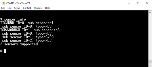
- List the supported sensors with the sensor_info command and collect their IDs using the command
$ sensor_infoas shown in the figure below.
- Select the desired sub-sensor, the accelerometer for instance, with the
sensor_setcommand:
$ sensor_set 0.0 enable 1
sensor 0.0: enable.enable
- You can further configure other parameters (Output Data Rate and full-scale settings) using sensor_set and sensor_get commands.
- Configure and run the device you want to monitor in normal operating conditions and start the data logging.
- Start data acquisition with the start datalog command
$ start datalog
- Stop data acquisition when enough data is collected with the stop command (or even more conveniently with hitting the ESC key)
$ stop
- Configure the monitored device for abnormal operation, start it .and repeat steps 6. and 7. During each data acquisition cycle, a new folder is created with the name
STM32_DL_nnn. The suffixnnnincrements by one each time a new folder is created, starting from 001. This means that if noSTM32_DL_nnndirectory pre-exists, directoriesSTM32_DL_001andSTM32_DL_002are created for normal and abnormal data respectively. Each created directory contains following files:DeviceConfig.json: the configurations used for the sensors to acquire data.AcquisitionInfo.json: File containing the information on the acquisition.SensorName_SubsensorMode.dat: the sensor acquisition data.
Alternatively, the data acquisitions can be made using the auto-mode provided in extended autonomous modes of the FP-AI-NANOEDG1. To achieve this, the user has to provide the required configurations of the sensors either through the default values in the Firmware or through a DeviceConfig.json file in at the root of microSD™ card, and an execution_config.json file to configure the settings of the auto mode. An example file for auto-mode to log the data is provided below.
{
	"info": {
		"version": "1.0",
		"auto_mode": true,
		"phases_iteration": 3,
		"start_delay_ms": 2000,
		"execution_plan": [
			"datalog",
			"idle"
		],
		"learn": {
			"signals": 0,
			"timer_ms": 0
		},
		"detect": {
			"signals": 0,
			"timer_ms": 0,
			"threshold": 90,
			"sensitivity": 1.0
		},
		"datalog": {
			"timer_ms": 30000
		},
		"idle": {
			"timer_ms": 10000
		}
	}
}
This file assumes the data logging will start after 2 seconds of power-up or reset. Then this configuration file will perform three iterations for the data logging, with 10-second long idle breaks which can be used to change the configurations of the monitoring machine, such as the speed of a motor or load on a motor.
5.2. Exporting the data collection to NanoEdge™ AI Compliant Data format
FP-AI-NANOEDG1 comes with utility Python™ scripts located in /FP-AI-NANOEDG1_V2.0.0/Utilities/AI_ressources/DataLog to export data from the STWIN datalog application to the NanoEdge™ AI Studio compliant format.
The datalogs generated with FP-AI-NANOEDG1 datalog are in the binary format as .dat files along with the DeviceConfig.json and AcquisitionInfo.json files. The .dat as it is are not human-readable and can not be used for the library generation. The script STM_DataParser.py parses the binary .dat files, and create .csv human-readable files. This function takes in input the path to a data directory that contains all the .dat files. Following are the example calls:
python STM_DataParser.py Sample-DataLogs/STM32_DL_001
python STM_DataParser.py Sample-DataLogs/STM32_DL_002
As a result, a .csv file is added to each directory.
These .csv files contain data, in human-readable format, so they can be interpreted, cleaned, or plotted. Another step is needed to export them to NanoEdge™ AI Studio required format as explained in cartesiam-neai-docs.readthedocs-hosted.com/studio/studio.html#expected-file-format. This is done using script, PrepareNEAIData.py. The script converts the data stream into frames of equal length. The length, which depends on the use case and features to be extracted, must be given as a parameter along with the good and the bad data folders (respectively STM32_DL_001 and STM32_DL_002 in the example) as follows:
python PrepareNEAIData.py Sample-DataLogs/STM32_DL_001 Sample-DataLogs/STM32_DL_002 -seqLength 1024
As a result, two .csv files are created:
# normalData.csv
# abnormalData.csv
Detailed script usage instructions and examples are provided in a Jupyter™ notebook located in the datalog directory (FP-AI-NANOEDG1-HSD-Utilities.ipynb). Samples of vibration dataset is provided provided in Utilities/AI_ressources/DataLog/Sample-DataLogs.
5.3. NanoEdgeTM AI Library Generation
The process of generating the libraries with Cartesiam NanoEdge AI studio consists of five steps.
- Hardware description
- Choosing the target platform or a microcontroller type: STEVAL-STWINKT1B Cortex-M4
- Maximum amount of RAM to be allocated for the library: Usually a few Kbytes will suffice (but it depends on the data frame length used in the process of data preparation, you can start with 32 Kbytes).
- Sensor type : 3-axis accelerometer
- Providing the sample contextual data to adjust and gauge the performance of the chosen model. This step will require data for:
- Nominal or normal case (
normalSegments.csv) - Abnormal case (
abnormalSegments.csv)
- Nominal or normal case (
- Benchmarking of available models and choose the one that complies with the requirements.
- Validating the model for learning and testing through the provided emulator which emulates the behavior of the library on the edge.
- The final step is to compile and download the libraries. In this process, the flag
"-mfloat-abi"has to becheckedfor using libraries with hardware FPU. All the other flags can be left to the default state.
Detailed documentation on the NanoEdge AI Studio.
.
5.4. Installing the NanoEdge™ library
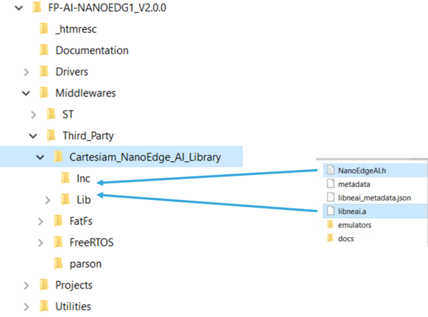
Once the libraries are generated and downloaded from NanoEdge™ AI Studio, the next step is to incorporate these libraries into FP-AI-NANOEDG1. The FP-AI-NANOEDG1 function pack comes with the library stubs replacing the current libraries generated by NanoEdge™ AI Studio. This makes it easy for users to link the generated libraries and have a place holder for the libraries that are generated as described in Section 4.2 Exporting the data collection to NanoEdge. To link the current libraries, the user must copy the generated libraries and replace the existing stub/dummy libraries libneai.a and header files NanoEdgeAI.h, present in the lib and inc respectively. The relative path of these folders is ./FP-AI-NANOEDG1_v2.0.0/Middlewares/Third_Party/Cartesiam_NanoEdge_AI_Library as shown in the figure below.
Once these files are copied, the project must be reconstructed and programmed on the sensor board to link the libraries. To perform these operations,
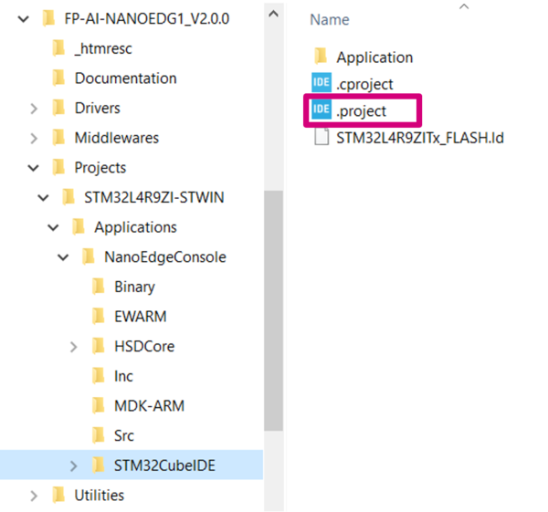
the user must open the .project file from the FP-AI-NANOEDG1 folder located at FP_AI_NANOEDG1_V2.0.0/Projects/STM32L4R9ZI-STWIN/Applications/NanoEdgeConcole/STM32CubeIDE/ as shown in the figure below.
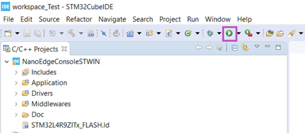
To install new firmware after linking the library, connect the sensor board, and rebuild the project using the play button highlighted in the following figure. Build and download the project in STM32CubeIDE.
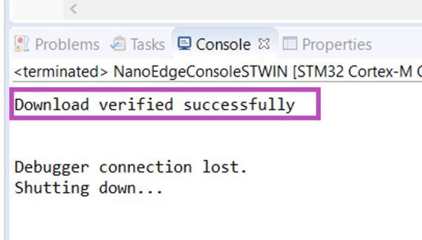
See the console for the outputs and wait for the build and download success message as shown in the following figure.
6. Building and programming
Once a new binary is generated through the build process with a Machine Learning library using NanoEdge™ AI Studio, the user can install it on the sensor node and start testing it in real conditions. To install and test it onto the target, the below steps are to be followed.
- Connect the STWIN board to the personal computer through an ST-LINK using a USB cable. This will make the STWIN board appear as a drive in the drive list of the computer, named something as
STLINK_V3M. - Drag and drop the newly generated
NanoEdgeConsoleSTWIN.binfile onto the driveSTLINK_V3M. - When the programming process is complete, connect the STWIN through the console and you should see a welcome message confirming that the stub has been replaced with the Cartesiam libraries as shown in the figure below.
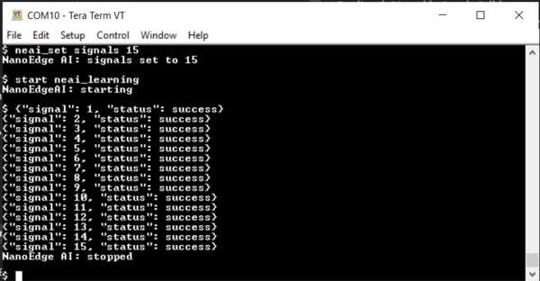
- To use these libraries for condition monitoring, the user must provide some learning data of the nominal condition. To do so, place the machine to be monitored in nominal conditions, and start the learning phase, either through the CLI console or by performing a long press on the user button, and observe the screen as shown in the following figure (if the console is attached), or the LED blinking pattern1 as indicated in the autonomous mode to show the learning has started.
The signals used for learning are counted. During the benchmark phase, a graph shows the number of signals to be used for learning in the form of minimum iterations. It is suggested to use between 3 to 10 times more signals than this number.
- Once the desired number of signals are learned, press the user button again to stop the process. The learning can also be stopped by pressing
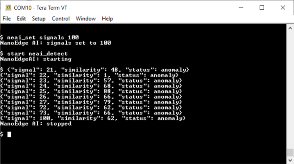
Escbutton or simply by enteringstopcommand in the console. Upon stopping the phase, the console will show a message sayingNanoEdge AI: stopped. - The anomaly detection mode can be started either through the console or by performing a short press on the user button. In the detection mode, the NanoEdge™ calculates the similarity between the observed signal and the nominal signals it has seen before. For normal conditions, the similarity is very high. However, for abnormal signals the similarity is low. If the similarity is low compared to a preset value, the signal is considered an anomaly, and the console shows the number of the bad signal along with the similarity calculated. However, the similarity for the normal signals is not shown.
- The detect phase can be stopped by pressing the user button again if the sensor node is being used in autonomous mode. When the console is connected the detect phase can be stopped also by pressing
Escbutton on the keyboard or by enteringstopcommand in the console. Upon stopping console shows a message sayingNanoEdge AI: stopped.
Note: Some practical use cases (such as ukulele, coffee machine, and others) and tutorials are available from the Cartesiam website:
- cartesiam-neai-docs.readthedocs-hosted.com/tutorials/ukulele/ukulele.html
- cartesiam-neai-docs.readthedocs-hosted.com/tutorials/coffee/coffee.html
7. Resources
7.1. Getting started with FP-AI-NANOEDG1
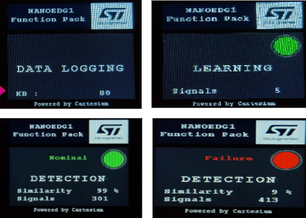
This wiki page provides a quick starting guide for FP-AI-NANOEDG1 version 1.0 for STM32L562E-DK discovery kit board. Other than the interactive CLI interface provided in the current version of the function pack, version 1.0 also had a simple LCD support, which is very convenient for demonstration purposes when operating in button-operated or battery-powered settings. The following are a few images that show the working of FP-AI-NANOEDG1 on STM32L562E-DK discovery kit board for data logging, learning and detection phases.
Users are also invited to read the user manual of version 1.0 for more details on how to set up a condition monitoring application on STM32L562E-DK discovery kit board using FP-AI-NANOEDG1.
7.2. How to perform condition monitoring wiki
This user manual provided basic information to a user on how to use the FP-AI-NANOEDG1. In addition to this, we also provide an application example of the FP-AI-NANOEDG1 on the STM32 platform where we perform the condition monitoring of a small motor provided in the kit GimBal motor. The How to perform condition monitoring on STM32 using FP-AI-NANOEDG1 provides a full example of how to collect the dataset for library generation with NanoEdge AI Studio using the data logging functionality, and then how to use the libraries to perform the unbalance detection for the motor.
7.3. Cartesiam resources
The function pack is to be powered by Cartesiam. The AI libraries to be used with the function pack are generated using the NanoEdge™ AI studio. The brief details on generating the libraries are provided in the section above but the more detailed information on it and some example projects can be found in the documentation of NanoEdge™ AI studio.
- DB4196: Artificial Intelligence (AI) condition monitoring function pack for STM32Cube.
- DB4345 : STEVAL-STWINKT1B.
- UM2777 : How to use the STEVAL-STWINKT1B Sensortile Wireless Industrial Node for condition monitoring and predictive maintenance applications.
