1. Introduction
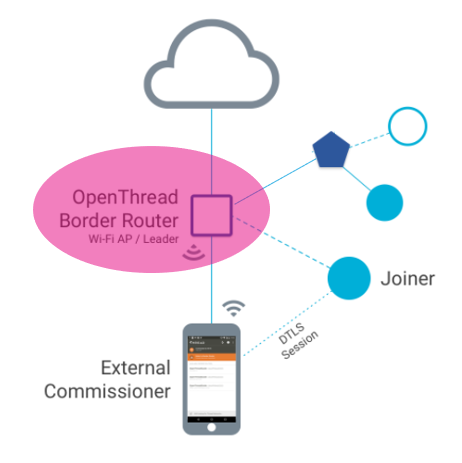
Each node forming the 802.15.4 network of the Thread implementation can act with the following roles: Leader, Router, End Device or Sleepy End Device (SED). A special role named Border Router allows the Thread nodes to access the outside world through an end-to-end IPv6 connection. A Thread Border Router (ie. Thread BR) connects a Thread network to other IP-based networks, such as Wi-Fi or ethernet. It is basically a bridge between Thread network and a Wi-Fi or ethernet interface.
| OpenThread Border Router |
|---|
A Thread Border Router supports at least, the following functions:
- Bidirectional IP connectivity between Thread and Wi-Fi/ethernet networks.
- Bidirectional service discovery via mDNS (on a Wi-Fi/Ethernet link).
- Thread-over-infrastructure that merges Thread partitions over IP-based links.
- External Thread commissioning (for example, a mobile phone) to authenticate and join a Thread device to a Thread network.
2. STM32WB Radio system
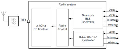
Bluetooth® Low Energy and 802.15.4 protocols share the same radio IP.
For more information, refer to the Getting started with Dynamic-concurrent mode BLE/Zigbee® on STM32WB Series microcontrollers application note [1].
| STM32WB Radio system |
|---|
3. OpenThread Border Router (OTBR) Application Setup
The border router is based on a Raspberry Pi (RPi) loaded with OTBR and an STM32WB' acting as RCP (Radio coprocessor). The RCP is controlled by the RPi as a remote Radio and all commands and data packets are sent from RPi to RCP and vice versa. The OTBR includes:
- a Bridge ethernet/WiFi to Thread
- an OpenThread stack (above MAC)
- a Local web server to server Web pages through WiFi AP
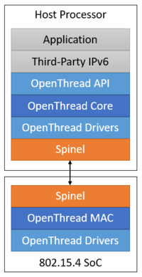
The OpenThread stack partitioning between RPi and STM32WB is as follows: the Host processor RPi is running the OpenThread core stack (OTBR), and the RCP is handling the low radio layers (sub-MAC and radio drivers). The host processor does not enter Sleep mode in this implementation, in part to ensure the reliability of the Thread network. The advantage is that OpenThread can utilize the resources from the most powerful processor. This design is useful for devices that are less sensitive to power constraints.
| OpenThread stack partitioning |
|---|
3.1. Hardware requirements
To set up a minimal running network, the following setup is required:
- 2 STM32WB are needed to demonstrate Thread BR (one attached with the RPi as RCP and another one forming a Thread network together with Thread BR).
- 1 FTDI cable (TTL-232R-RPi), used to allow communication RPi and STM32WB RCP.
- Regarding RPi:
- A Raspberry Pi 3B or newer
- Rpi’s External 5V AC adapter for power
- A microSD card of at least 64GB ("SD card" in this guide). Choose a Samsung or Sandisk SD card brand as it has been demonstrated by the RPi community to be much more reliable than the other manufacturers
- A direct internet connection with no VPN through ethernet
- USB keyboard
- HDMI capable screen
- Ethernet cable to directly connect to an internet ISP box
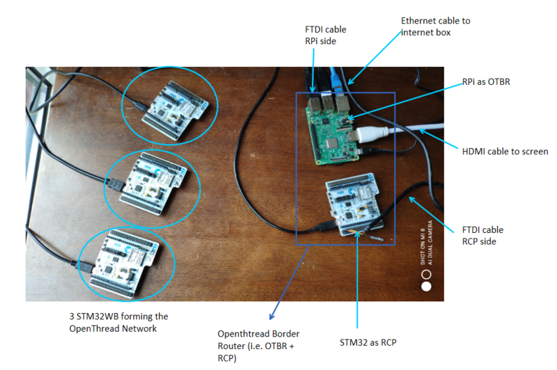
The following picture depicts four nodes OpenThread network.
| 4 Nodes OpenThread Network |
|---|
3.2. STM32WB RCP setup
3.2.1. STM32WB RCP hardware connection
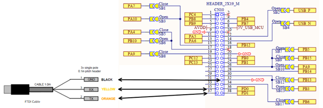
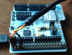
The communication with RPi is done through a serial connection. For RCP implementation, UART Rx/Tx are routed to external connector CN10 pin 35 (Tx) and pin 37 (Rx). So use the FTDI cable to connect its Rx connector (usually the yellow one) to CN10 pin 35 and its Tx connector (usually the orange one) to CN10 pin 37. Black connector (i.e. ground) can be found on CN10 pin 32.
| STM32WB RCP hardware connection |
|---|
3.2.2. STM32WB RCP software setup
A dedicated application called Thread_RCP must be flashed. Thread_RCP Application is available from STM32Cube_FW_WB V1.12.0. This application requires stm32wb5x_Thread_RCP_fw.bin binary to be flashed on the wireless coprocessor. If this is not the case, the STM32CubeProgrammer must be used to load the appropriate binary. All available binaries are located under /Projects/STM32_Copro_Wireless_Binaries directory. Refer to STM32CubeProgrammer software description application note [2] to learn how to use/install STM32CubeProgrammer. Refer to /Projects/STM32_Copro_Wireless_Binaries/ReleaseNote.html for the detailed procedure on how to change the Wireless Coprocessor binary. Once the wireless coprocessor flashed, the Thread_RCP application must be built and uploaded. To carry out this operation, follow the steps below:
- Connect an STM32WB55xx_Nucleo board to your PC.
- Open your preferred toolchain.
- Rebuild all files and load your image, or use the Thread_RCP_reference.hex from binary directory.
- Connect one HyperTerminal (ST_Link) to be able to get the RCP running logs.
On joiner node side, the stm32wb5x_Thread_FTD_fw.bin is to be flashed using STM32CubeProgrammer. The dedicated application is the following:
- Thread_Cli_Cmd.bin: if using v1.12.0, which requires CLI commands typing.
- Thread_RCP_Cli_Cmd.bin: if using v1.13.0 or newer, which enables a 1 push button commissioning feature.
Both usages are depicted in the “how to launch the demo” section.
3.3. RPi setup
3.3.1. RPi hardware connection
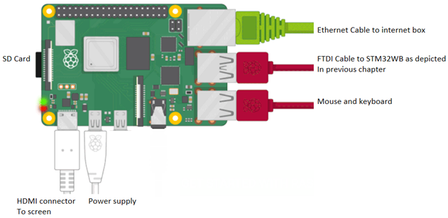
Connect the USB part of the FTDI cable to one of the available RPi USB port. Also use the USB ports to connect a mouse and a keyboard. Connect an HDMI cable to the dedicated screen. The SD card must first be flashed with the OTBR_CLI_RPi_1.0.img, then power can be supplied through the microUSB.
| RPi hardware connection |
|---|
3.3.2. RPi software setup
A full configured RPi image is provided by ST. Get the OTBR_CLI_RPi_1.0.img. To flash this image onto your SD Card, download and install Win32DiskImager from the Win32DiskImager [3].
- Insert the SD Card to be Flashed.
Insert a blank (or used and nuked) SD card into the SD card reader on your Windows computer.
- Prepare the SD Card to be Flashed.
Click on the Start menu icon and type disk management and press the Return key to locate and open the Disk Management program.
| SD Card Preparation |
|---|
Secondary-click on the drive in the volume column to bring up the context-sensitive menu and delete all the partitions on the SD card (if there are any). Format the SD Card as FAT–32 or NTFS, as these file systems are recognized by Windows computers, by secondary-clicking to bring up the context-sensitive menu and select Format.
- Flash a Disk Image to an SD Card
Launch Win32DiskImager. Click on the blue folder icon and browse to the location where you previously saved your Raspberry Pi SD card image file, ending .img, in my example OTBR_CLI_RPi_1.0.img.
Under Device, select the drive letter of your SD card, in my example E: and click Write button.
You will see a warning dialogue box saying: Writing to a physical device can corrupt the device. (Target device [E:] “RPI”) Are you sure you want to continue?
Make sure the correct SD card destination is selected and click the Yes button. Once again, the progress bar appears to give you an indication on how long the process will take to complete.
When completed, eject the SD card from the SD card reader and insert it in your RPi.
3.4. Thread nodes setup
You need at least one spare Thread node. To do so, refer to the Thread_Cli_Cmd (with v1.12.0) or Thread_RCP_Cli_Cmd.bin (with v1.13.0) application readme.txt to setup properly your nodes. Also open a terminal (like Teraterm or Putty) and connect it to the COM port of your node.
4. How to launch the Demo
4.1. OpenThread Border Router configuration
Note that the RPi image delivered by ST embeds the RPi OS Lite image already configured to provide services like :
- Dedicated Web Server on a defined IPv4 Address (192.168.1.2)
- DnsMasq for DNS (and DHCP) services
- Hostpad that allows to use RPi's built-in WiFi radio as an AP
- NAT configuration with tayga and iptables
| OpenThread Border Router Overview |
|---|
Once the RPi has booted up, you will be asked to log in:
- login: pi
- password: raspberry
Set up Wi-Fi on RPi : Open command prompt and execute the following command to setup/enable the Wi-Fi
- ifconfig –a
- ifconfig wlan0 up
- Scan available SSID (AP)↑
* iw dev wlan0 scan |grep SSID
- Configure Wi-Fi connection by using wpa_supplicant file
* cat /etc/wpa_supplicant.conf
- Set the Wi-Fi network name and password
* wpa_passphrase <your_ssid_name> <your_ssid_key> >> /etc/wpa_supplicant.conf
- Connect to SSID
* wpa_supplicant -B -iwlan0 -c /etc/wpa_supplicant.conf
- Link to SSID
* iw wlan0 link
- Use the DHCP client to obtain an address
* dhclient wlan0
- Use the ip command to verify the IP address assigned by the DHCP.
* ip addr show wlan0
Then check the connectivity by using the “ping” command.
Troubleshoot in Wi-Fi setting :
- In some cases Wi-Fi is block therefore user can execute "sudo rfkill unblock wifi" command to unblock the Wi-Fi
- If country code is not defined in wpa_supplicant.conf then user can execute following command to SET country code (for INDIA its IN):
    *Sudo raspi-config nonint do_wifi_country IN
    * User can directly SET country code in file :
            * Sudo nano /etc/wpa_supplicant/wpa_supplicant.conf
            * Country=IN
            * save file and reboot the RPi
Check which tti the FTDI cable has been mounted in order to determine the serial port name for the RCP. By default, ttyUSB0 is handled by the launching script provided by ST.
Open a Terminal and type: ls /dev/tty*
You should see:
| Terminal |
|---|
If ttyUSB0 is not used, you have to modify the launching script. To do, edit /etc/default/otbr-agent with:
OTBR_AGENT_OPTS="-I wpan0 spinel+hdlc+uart:///dev/ttyUSB0"
Reboot the RPi after modification.
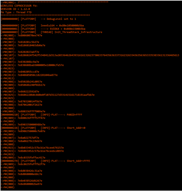
During the boot sequence, RPi is automatically launching the OTBR stack and starts to communicate with the RCP. If RCP is not connected during bootup, OTBR is polling on RCP presence so it can be connected later. When the communication between OTBR and the RCP starts, OTBR is first resetting the RCP, gathering the different version of Spinel and OpenThread embedded in the RCP, then configuring it with default values like the PANID to 0xFFFF, the short address to 0xFFFE.
The following figure displays the logs on the RCP side.
| RCP logs |
|---|
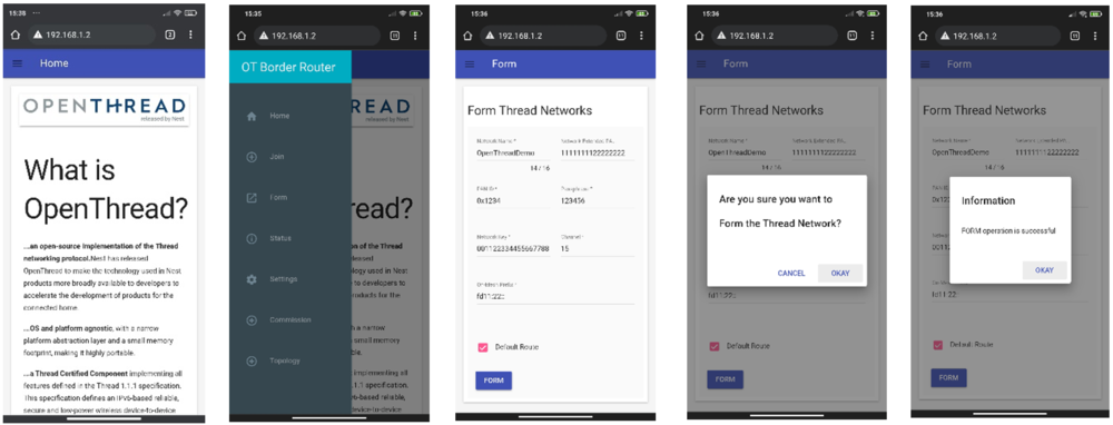
4.2. Form the Thread Network
802.15.4 network is configured using a web interface via WiFi interface.
- Connect your smartphone to the BorderRouter-AP WiFi AP (password: 12345678).
- Launch Chrome on your smartphone on 192.168.1.2 fixed IP address
- Click the menu button and choose Form
- Confirm forming and it takes 3 to 4 seconds to configure the Network
| Network configuration |
|---|
4.3. Commission a Thread Node to the Thread Network
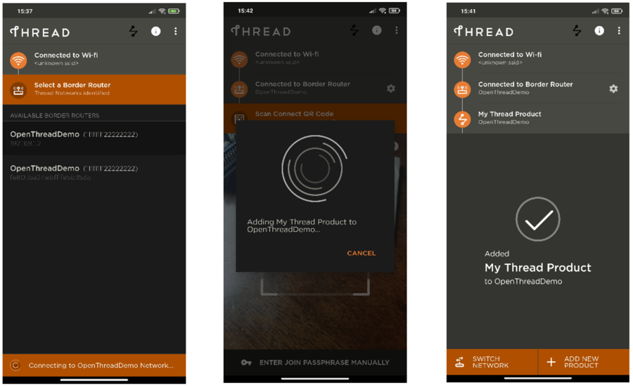
The Thread Group provides an Android application to enable external commissioning. The application can be downloaded via Google Play Store or trough the Thread 1.1 Commissioning App link [4].
Launch the application. If it is not connected on Border Router automatically, do it manually by using the 192.168.1.2 IPv4 address.
Application needs to flash a QR Code of the joiner node. The QR code can be generated using this kind of site [5].
- First, to get your device EUI, connect a terminal on the device COM port and type the CLI commande eui64.
- Then, generate the QR code using the following Text:
v=1&&eui=<your device eui64>&&cc=STM32WB
- Flash the generated QR code with the Thread application.
At this stage, the Border Router is waiting for the external node to start the joining sequence.
- If you are using version 1.13.0, press SW1 button. The blue LED starts to blink slowly during the commissioning phase. Once commissioning succeeds, the blue LED stays solid. If an error occurs, LED will rapidly blink 2 to 3 seconds then switch off.
- If you are using 1.12.0, type the following CLI commands on the Terminal:
| CLI commands |
|---|
In both cases, the application displays the following UI:
| Thread App screenshots |
|---|
4.4. Ping public address
Try the following ping commands to address various servers:
ping 64:ff9b::acd9:a46e  // GOOGLE
ping 64:ff9b::808:808    // server DNS Google
ping 64:ff9b::d90c:030b  // Yahoo! Europe
You should have the following result:
| Ping Commands output |
|---|
5. Acronyms and definitions
| Term | Definition |
|---|---|
| OTBR | OpenThread Border Router |
| RCP | Radio co-processor |
| RPi | Raspberry Pi |
