1. Introduction
The OTA (Over-The-Air) feature enables Zigbee devices to update their firmware wirelessly. The OTA server provides the latest binary version for OTA clients to download and install. Implementing the OTA feature involves using the Exegin OTA Cluster. For more detailed guidance, refer to the "Getting Started with Zigbee® on STM32WB Series" application note [1].
2. STM32WB OTA use case
The Zigbee_OTA application is available by downloading the latest STM32CubeWB[2] release.
To perform a Zigbee OTA update, you need at least two STM32WBxx boards running the Zigbee protocol:
- One board running the ZigBee_Ota_Server application (with the ZbZclOtaServer cluster allocated).
- One or more boards running the ZigBee_Ota_Client application (with the ZbZclOtaClient cluster allocated).
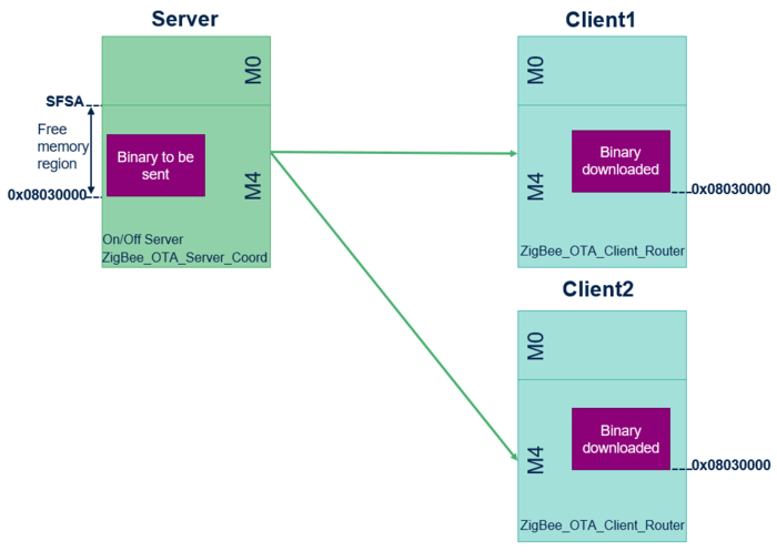
An OTA upgrade can be conducted for multiple clients simultaneously. First, the binary to be downloaded must be flashed onto the "free" memory region of the server using tools like STM32CubeProgrammer. In this use case, the binary is flashed at address 0x08030000. The server then initiates the OTA provisioning process and proposes an update to the clients, who can choose to upgrade. The binary is transferred and flashed onto the "free" memory region of the client, also at address 0x08030000.
| OTA Server/Client model |
|---|
During the application update, the server transfers the binary to the client. Once the client receives all the frames of the binary, the device reboots. The binary can be intended for either the M4 application or the M0 coprocessor wireless binary.
2.1. Application update (M4)
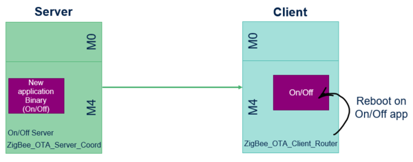
The OTA process verifies that the downloaded binary is intended for the M4 application and checks its integrity code. Once verification is complete, the OTA launches the new application firmware, such as the On/Off app.
| Application update |
|---|
2.2. Coprocessor wireless binary update (M0)
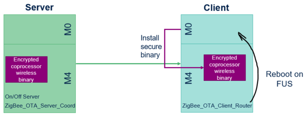
If the downloaded binary is for the coprocessor M0, the OTA process checks the integrity code and reboots into the FUS (Firmware Upgrade Service). Once completed, the wireless coprocessor installs the secure binary and reboots back into the OTA. The OTA is then prepared to receive the new M4 firmware, which must always be updated and flashed following an M0 update.
| Coprocessor wireless binary update |
|---|
3. OTA Upgrade principle
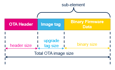
The OTA upgrade is based on a specific file format composed of :
- OTA header
- OTA sub-element (Upgrade image tag + associated binary firmware data)
| OTA File Format |
|---|
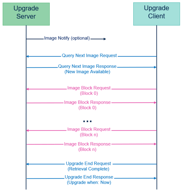
The binary is stored in the server's flash memory at address 0x08030000. The server retrieves the CRC and binary size, then sends an image notification to all clients in the network, specifying the image type and version. Clients interested in upgrading must use the "Query Next Image" request. Upon receiving a response to this request, the client checks its device capabilities before downloading the image. It compares the available flash memory size with the requested image size.
The server cannot send the image as a single block. The block size is constrained by:
- ZCL_OTA_BLOCK_DATA_SIZE_NWKSEC_MAX: 49 bytes if only network security is applied, without APS security.
- ZCL_OTA_BLOCK_DATA_SIZE_APSSEC_MAX: 40 bytes if both network and APS security are applied.
| OTA Upgrade Diagram |
|---|
4. OTA Cluster APIs Functions
The following table lists some examples of APIs used with OTA cluster.
| Function | Description |
|---|---|
| ZbZclOtaClientAlloc | Create new OTA client cluster |
| ZbZclOtaServerAlloc | Create new OTA server cluster |
| ZbZclOtaClientDiscover | Discover OTA server |
| ZbZclOtaClientDiscoverForced | Set the OTA server directly |
| ZbZclOtaClientImageTransferResume | Resume an OTA upgrade transfer |
| ZbZclOtaClientImageTransferStart | Initiate an OTA transfer |
5. Resuming a partial download
If the binary download is interrupted, the application can resume the transfer, depending on the interruption's cause:
- If the OTA server turns off, the application waits until the connection is reestablished and resumes the transfer by calling
ZbZclOtaClientImageTransferResume. - If the OTA client turns off after receiving and saving part of the firmware, the transfer can resume from the previous download point using the
FileOffsetattribute.
6. Slowing down the OTA with image_block_delay
If an OTA resume methodology is assessed for any reason, a method to increase the robustness of the OTA transfer is to increase the delay between image block requests (from block n to block n+1) using the parameter image_block_delay on the client side. The default value for image_block_delay is 50ms. Increasing the image_block_delay to 100ms will slow down the OTA transfer by a factor of two. Slowing down the OTA might be necessary in noisy environments or when the image needs to be transmitted through multiple routers (multiple hops).
STM32WBA code to modify the value of image_block_delay:
  stOTAClientConfig.profile_id = APP_ZIGBEE_PROFILE_ID;
  stOTAClientConfig.endpoint = APP_ZIGBEE_ENDPOINT;
  stOTAClientConfig.image_block_delay = 250u;
  stOTAClientConfig.activation_policy = ZCL_OTA_ACTIVATION_POLICY_SERVER;
  stOTAClientConfig.timeout_policy = ZCL_OTA_TIMEOUT_POLICY_APPLY_UPGRADE;
STM32WB code to modify the value of image_block_delay:
static struct ZbZclOtaClientConfig client_config = {
  .profile_id = ZCL_PROFILE_HOME_AUTOMATION,
  .endpoint = SW1_ENDPOINT,
  .image_block_delay = 250U,
  .activation_policy = ZCL_OTA_ACTIVATION_POLICY_SERVER,
  .timeout_policy = ZCL_OTA_TIMEOUT_POLICY_APPLY_UPGRADE };
7. Details on OTA Data Size
The data size for an OTA has a minor impact on the duration of the OTA image transfer. This chapter details the headers that directly impact the number of bytes available for the OTA data size. Some network parameters also affect the OTA data size, which has been arbitrarily chosen to be 49 bytes. This conservative choice allows for a wide range of network topologies and all possible security levels and can be considered a stack requirement.
In the context of Zigbee, the Maximum Transmission Unit (MTU) size refers to the maximum size of a data packet that can be transmitted over the network, including both the header and the payload. The Zigbee protocol typically supports a maximum MTU size of 127 bytes at the physical layer. These 0-127 bytes are also called PSDU for PHY Service Data Unit and are referred to as IEEE 802.15.4 data in Wireshark.
In the context of Zigbee OTA, the "ZCL OTA: image block request" frames and "ZCL OTA: image block response" frames are ZCL frames. These frames are used within the Zigbee protocol to facilitate communication between devices using the Zigbee Cluster Library. These frames typically contain:
- MAC Header: Includes frame control, sequence number, addresses, etc.
- NWK Header: Includes network-specific information like source and destination addresses, radius, etc.
- APS Header: Application support sub-layer information.
- ZCL Header: Zigbee Cluster Library-specific information.
- Payload: The actual data being transmitted.
- Security Overhead: If security is enabled, additional bytes are used for the auxiliary security header and Message Integrity Code (MIC).
7.1. Zigbee ZCL OTA:image block request Frame typical exemple for STM32WBA Structure
7.1.1. 1. MAC Layer
- Frame Control: 2 bytes
- Sequence Number: 1 byte
- Destination PAN ID: 2 bytes
- Destination Address: 2 bytes (short address) or 8 bytes (extended address)
- Source Address: 2 bytes (short address) or 8 bytes (extended address)
7.1.2. 2. NWK Layer
- Frame Control: 2 bytes
- Destination Address: 2 bytes
- Source Address: 2 bytes
- Radius: 1 byte
- Sequence Number: 1 byte
7.1.2.1. Optional NWK Security
- Auxiliary Security Header: 5 to 14 bytes (depending on security level)
- Security Control: 1 byte
- Frame Counter: 4 bytes
- Extended Source Address: 0 or 8 bytes (optional)
- Key Sequence Number: 0 or 1 byte (optional, positioned after Extended Source Address)
- Message Integrity Code (MIC): 4 bytes
7.1.3. 3. APS Layer
- Frame Control: 1 byte
- Destination Endpoint: 1 byte
- Cluster ID: 2 bytes (0x0019 for OTA)
- Profile ID: 2 bytes (0x0104 for Zigbee HA)
- Source Endpoint: 1 byte
- APS Counter: 1 byte
7.1.4. 4. ZCL Layer
- Frame Control: 1 byte
- Transaction Sequence Number: 1 byte
- Command ID: 1 byte (0x05 for image block response)
Payload
- Status: 1 byte
- Manufacturer Code: 2 bytes
- Image Type: 2 bytes
- File Version: 4 bytes
- File Offset: 4 bytes
- Data Size: 1 byte (set to 49)
- Image Data: 49 bytes
7.2. Example Byte-by-Byte Breakdown
<MAC Layer:
Byte 0-1: Frame Control
Byte 2: Sequence Number
Byte 3-4: Destination PAN ID
Byte 5-6: Destination Address
Byte 7-8: Source Address

NWK Layer:
Byte 9-10: NWK Frame Control (2 bytes)
Byte 11-12: Destination Address
Byte 13-14: Source Address
Byte 15: Radius
Byte 16: NWK Sequence Number

Optional NWK Security:
Byte 17: Security Control
Byte 18-21: Frame Counter
Byte 22-29: Extended Source Address (if used)
Byte 30: Key Sequence Number (if used)
Byte 31-34: MIC (4 bytes)

APS Layer:
Byte 35: APS Frame Control
Byte 36: Destination Endpoint
Byte 37-38: Cluster ID (0x0019 for OTA)
Byte 39-40: Profile ID (0x0104 for Zigbee HA)
Byte 41: Source Endpoint
Byte 42: APS Counter

ZCL Layer:
Byte 43: ZCL Frame Control
Byte 44: Transaction Sequence Number
Byte 45: Command ID (0x05 for image block response)

Payload:
Byte 46: Status
Byte 47-48: Manufacturer Code
Byte 49-50: Image Type
Byte 51-54: File Version
Byte 55-58: File Offset
Byte 59: Data Size (set to 49)
Byte 60-108: Image Data (49 bytes)
To link it with some Zigbee STM32WB or STM32WBA stack parameters:
Network Layer (NWK) Security: When NWK security is enabled, an auxiliary security header and a Message Integrity Code (MIC) are added to the NWK frame. The size of these security components depends on the chosen security level.
#define ZB_NWK_CONST_MIN_HEADER_OVERHEAD 0x08U
#define ZB_NWK_CONST_SECURITY_LEVEL 0x05U
#define ZB_SEC_MIC_LENGTH_5 4U
#define ZB_NWK_CONST_SECURITY_OVERHEAD (14U + 4U=18U)
Those 18 Bytes of ZB_NWK_CONST_SECURITY_OVERHEAD are taken into account in the previous chapter Example Byte-by-Byte Breakdown.
Source Routing Overhead: Many-to-one source routing adds overhead to the NWK header. Each hop in the source route requires additional bytes. With a source routing level of 6, the NWK header needs to accommodate the addresses of 6 intermediate nodes.
/* Source Routing Overhead */ 4U
/* source router header */ 2U * ZB_NWK_CONST_DEFAULT_SOURCE_ROUTE
#define ZB_NWK_CONST_DEFAULT_SOURCE_ROUTE 6U
Those 4+2*6=16 bytes of source routing overhead are not taken into account in the previous chapter Example Byte-by-Byte Breakdown.
8. References
