Click here for Bluetooth® Low Energy Overview.
Click here for an Introduction to Bluetooth® Low Energy with STM32.
1. Introduction
STM32CubeMX tool is a graphical tool that helps you generate an application targeting the STMicroelectronics MCU of your choice, with initialization code based on the configuration you specify. In the tools interface, you can select your STMicroelectronics MCU, configure pins, clocks, peripherals, and middleware, and generate the code project based on your setup.
This wiki page demonstrates how to generate a Bluetooth® Low Energy server application for an STM32WBA55CG MCU using STM32CubeMX.
2. Build a Bluetooth® Low Energy application on STM32WBA with STM32CubeMX
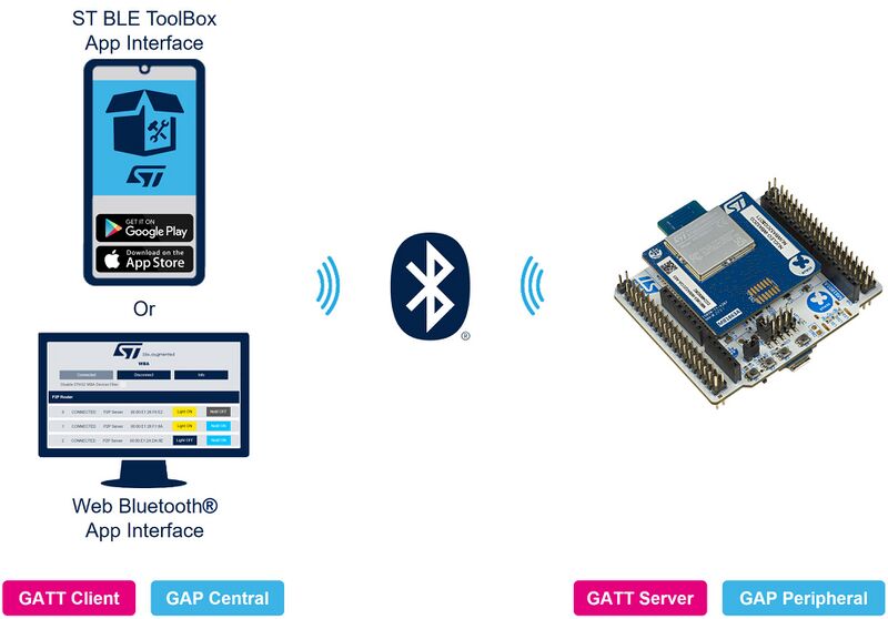
The STM32WBA Nucleo board, programmed with the application generated by STM32CubeMX, can send data to a smartphone (using the ST BLE ToolBox application), and receive commands from it through Bluetooth® Low Energy.
| System presentation |
|---|
A Generic Attribute (GATT) server application will be able to expose some user services. Note that the Generic Access Profile (GAP) and GATT services are automatically added to the list of user services. For our peer-to-peer (P2P) server application, we use two user services:
- The first service exposes two characteristics.
- The second service exposes three characteristics.
The first service (My_P2P_Server) looks like a P2P server (STM proprietary) with two characteristics:
- Characteristic 1 has Write property.
- Characteristic 2 has Notify property.
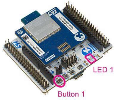
Writing to characteristic 1 toggles the blue LED.
Pressing Button 1 on the Nucleo board sends data to the phone.
| Custom Service |
|---|
The following steps are recommended to build this application example:
Service and characteristic configurations are given in the following table:
| Service Long Name | My_P2P_Server | |
|---|---|---|
| Service Short Name | My_P2P | |
| UUID Type | 128 bits | |
| UUID | 0xFE40 | |
| Characteristic Long Name | My_LED_Char | My_Switch_Char |
| Characteristic Short Name | LED_C | SWITCH_C |
| UUID Type | 128 bits | 128 bits |
| UUID | 0xFE41 | 0xFE42 |
| Char Properties | Read + Write w/o response | Notify |
| Char Permissions | None | None |
| Char GATT Events | GATT_NOTIFY_ATTRIBUTE_WRITE | GATT_NOTIFY_ATTRIBUTE_WRITE |
3. Tools
3.1. Software tools
To make and use this application project, you need the following software tools:
- STM32CubeMX[1] software
- STM32CubeWBA MCU package[2]
- IDE: STM32CubeIDE[3] or IAR[4]
- Your preferred serial terminal (e.g. TeraTerm)
- ST BLE ToolBox Smartphone application
The following demonstration was done with:
- STM32CubeMX v6.14.0
- STM32CubeWBA MCU package v1.6.0
3.2. Hardware tools
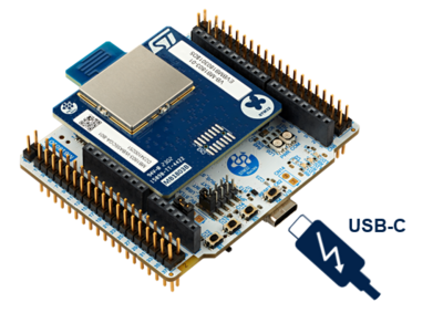
You also need an STM32WBA Nucleo board and a USB Type-C® cable
| Hardware presentation |
|---|
4. STM32CubeMX initialization for STM32WBA Nucleo board
With the STM32CubeMX software tool, it is possible to start your project at different levels: directly from the chip, from boards with the hardware support already configured, or directly from an embedded application developed by STMicroelectronics.
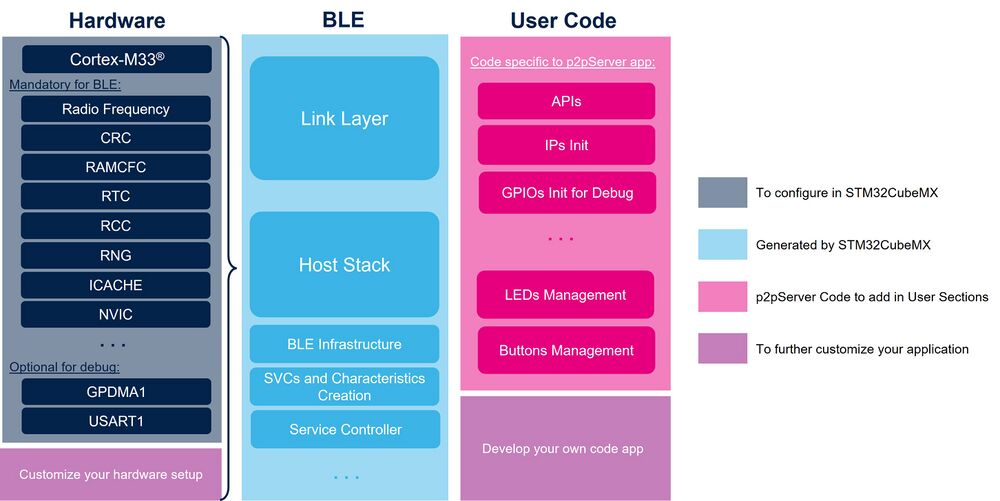
In this example, we will start with the STM32WBA55CG chip to detail all the configuration steps to enable Bluetooth® Low Energy and create an application. In this case, it will be a P2P server application.
| STM32WBA application design with STM32CubeMX for a P2P server application |
|---|
4.1. STM32CubeMX initial setup
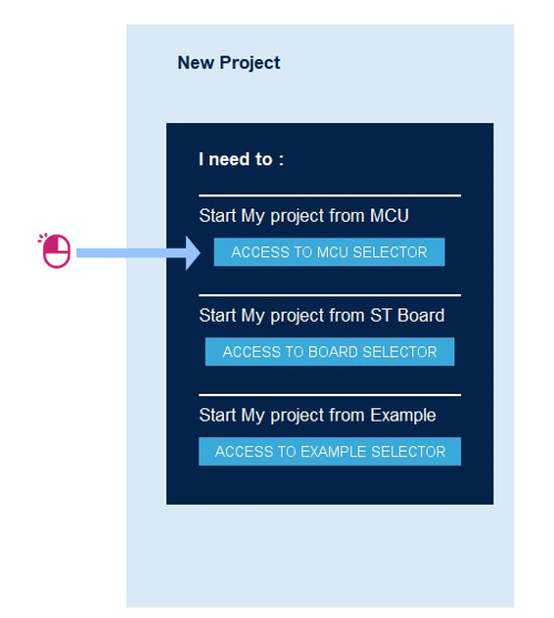
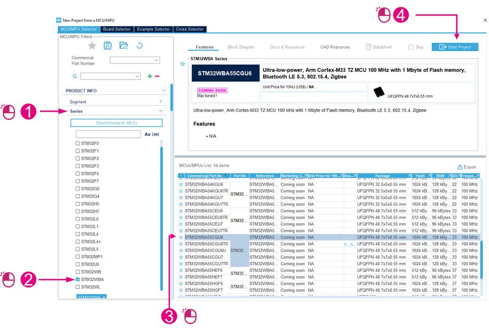
Open STM32CubeMX and start a new project by clicking on the Access to MCU selector button:
| New Project menu |
|---|
Select the correct MCU and start the new project:
| Project interface |
|---|
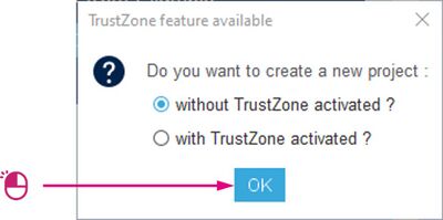
Start the new project without activating TrustZone:
4.2. Pinout and IP configuration
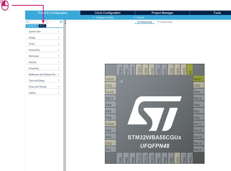
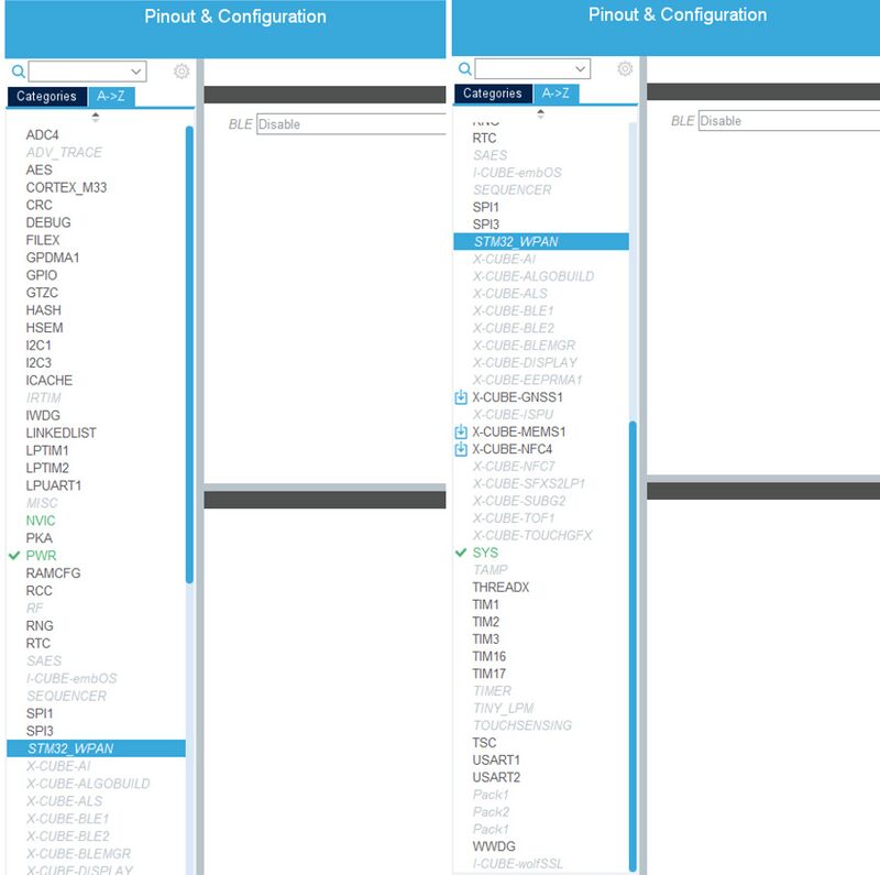
To configure the system, enable all the required system resources and peripherals by clicking on the A->Z tab to display all IPs.
| Pinout & configuration interface |
|---|
Bluetooth® Low Energy mode is reachable once the following system resources and peripherals are set to "enabled".
Mandatory:
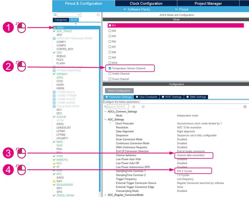
- ADC4: activate the temperature sensor channel
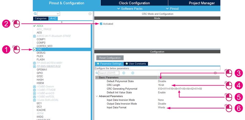
- CRC: activated
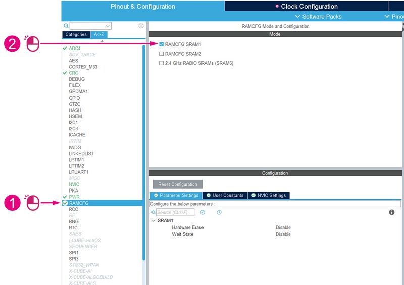
- RAMCFC: activate SRAM1
- ICACHE: 1-way (direct mapped cache)
- RNG: activated
- RCC: HSE and LSE on crystal/ceramic resonator
- RF: activated
- RTC: activate clock source
- NVIC: verify NVIC settings
Optional:
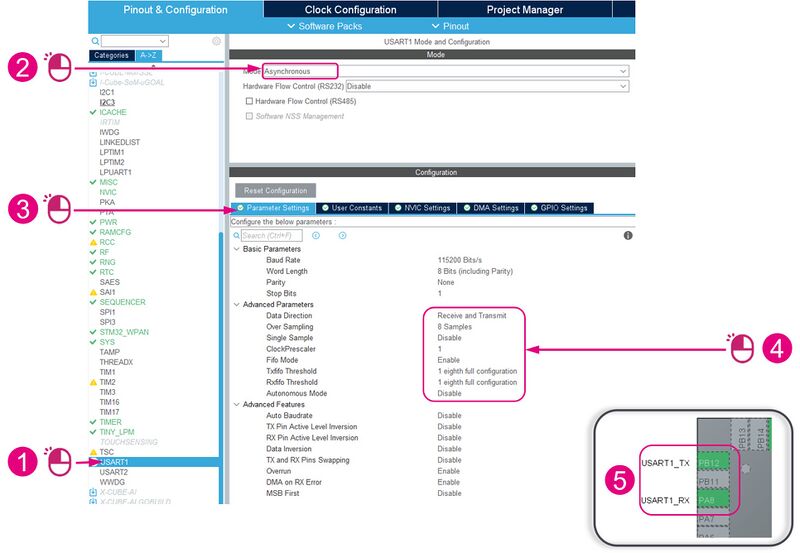
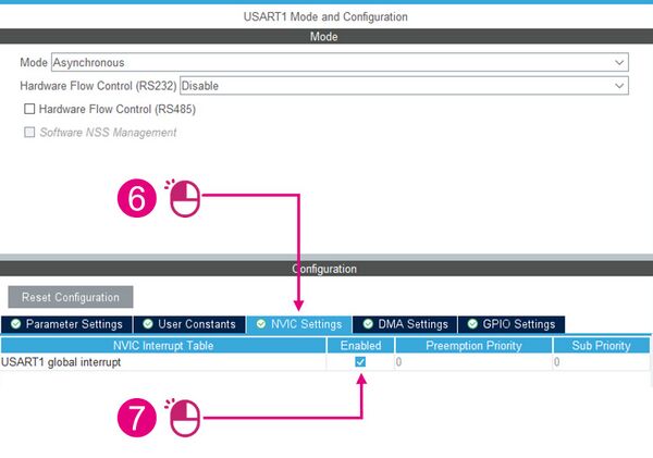
- USART1: set mode to asynchronous
- GPDMA1: configure channels 0 & 1
| ADC4 | By default, PHY calibration is based on temperature. Therefore, the temperature sensor channel must be activated. | |
| CRC | The cyclic redundancy check is used to verify Bluetooth® Low Energy data transmission or storage integrity. | |
| RAMCFG | Activating an SRAM is mandatory for the application. We dynamically modify the RAM configuration (System Clock Manager (SCM) module). This allows us to manage cases where we use low power, for example. | |
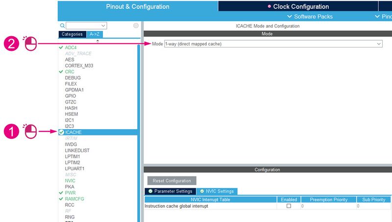
| ICACHE | The instruction cache (ICACHE) is introduced on the C-AHB code bus of the ARM Cortex-M33® processor to improve performance when fetching instructions and data from internal memories. | |
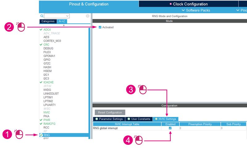
| RNG | The random number generator (RNG) provides the application with full entropy outputs as 32-bit samples. It is necessary to activate it, because the link layer regularly requests RNG. | |
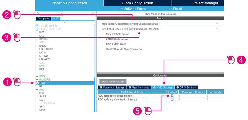
| RCC | Reset and Clock Control manages the different kind of reset and generates all clocks for the bus and peripherals. | |
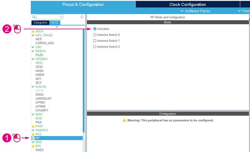
| RF | The Radio system is mandatory for a BLE project. | |
| RTC | The real-time clock (RTC) provides an automatic wake-up to manage all low-power modes. | |
| NVIC | All interrupts including the core exceptions are managed by the nested vectored interrupt controller (NVIC). | |
| USART1 | USART1 is enabled to allow the display of traces on a terminal. | |
| GPDMA1 | The general purpose direct memory access controller (GPDMA) is used to perform programmable data transfers between memory-mapped peripherals and/or memories via linked-list, upon the control of an off-loaded CPU. | |
| IP list |
|---|
4.2.1. Automatic configuration for a BLE project
| Automatic configuration for a BLE project |
|---|
4.2.2. ADC4
The 12-bit Analog to Digital Converter (ADC4) has external and two internal (temperature sensor, voltage reference measurement) channels and performs conversions in single-shot or scan modes.
By default, PHY calibration is based on temperature. Therefore, the temperature sensor channel must be activated.
| ADC4 configuration |
|---|
4.2.3. CRC
The Cyclic Redundancy Check (CRC) is used to verify Bluetooth® Low Energy data transmissions or storage integrity.
| CRC activation |
|---|
4.2.4. USART1
USART1 is enabled to allow the display of traces on a terminal.
| USART1 configuration (1/2) |
|---|
| USART1 configuration (2/2) |
|---|
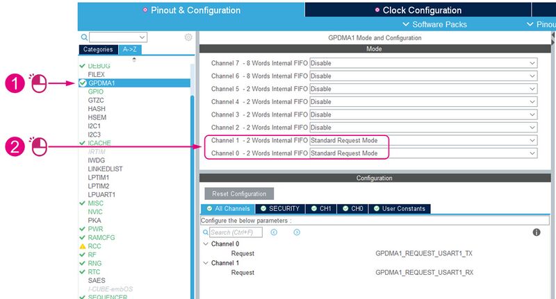
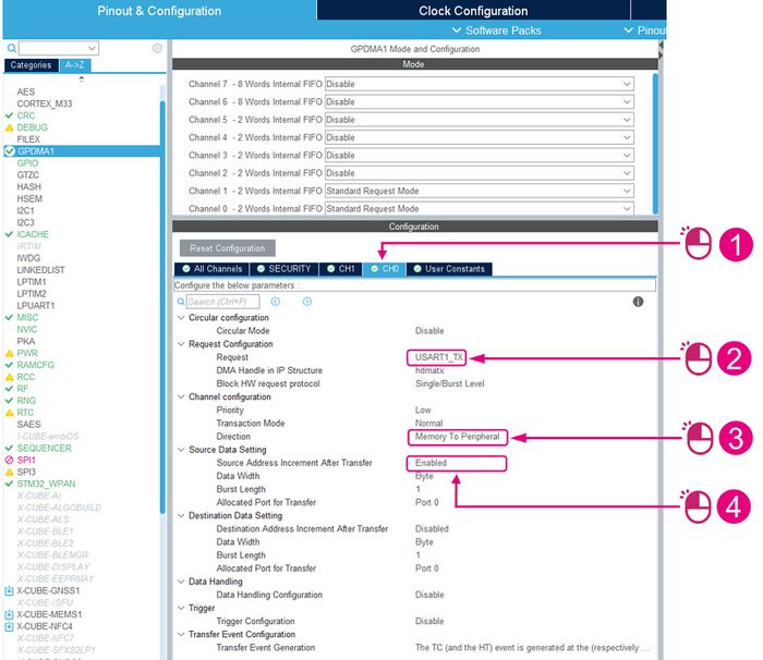
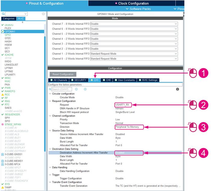
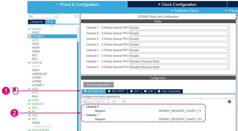
4.2.5. GPDMA1
The General Purpose Direct Memory Access (GPDMA) controller is a bus master and system peripheral. GPDMA is used to perform programmable data transfers between memory-mapped peripherals and/or memories via linked-list, upon the control of an off-loaded CPU.
| GPDMA1 configuration (1/4) |
|---|
| GPDMA1 configuration (2/4) |
|---|
| GPDMA1 configuration (3/4) |
|---|
| GPDMA1 configuration (4/4) |
|---|
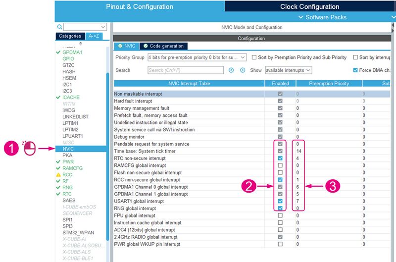
4.2.6. NVIC
The Nested Vector Interrupt Controller (NVIC) and the processor core interface are closely coupled, enabling low-latency interrupt processing and efficient processing of late-arriving interrupts. The NVIC manages all interrupts including core exceptions.
| NVIC configuration |
|---|
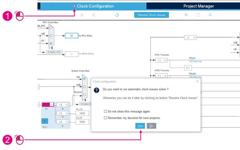
4.3. Clock configuration
In the Clock Configuration tab, run the automatic clock issue solver (if requested).
The following configuration is defined for the initial startup phase. At runtime, clocks will be managed dynamically by the System Clock Manager (SCM) module.
Then:
| Clock configuration |
|---|
5. Bluetooth® Low Energy GAP/GATT Custom application configuration
Now, we can start configuring and defining the STM32 Wireless Personal Area Network (WPAN).
- The Bluetooth® Low Energy Peripheral Custom Template GATT Server Application can be defined:
- on STM32WBA.
- with STM32CubeMX (starting from version 6.8.0).
- GAP peripheral: advertising configuration
- GATT server configuration:
- 25 services maximum.
- 25 characteristics maximum per service.
- ACI commands:
- AN5270: STM32WBx5 Bluetooth® Low Energy wireless interface[5].
- AN5270: STM32WBx5 Bluetooth® Low Energy wireless interface[5].
5.1. Advertising configuration
| STM32_WPAN interface: Bluetooth® Low Energy advertising configuration |
|---|
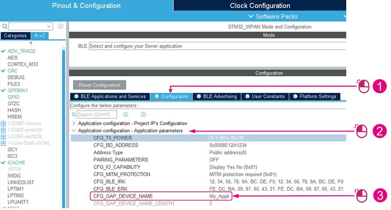
This array is defined in the app_ble.c file with the following code:
static const char a_GapDeviceName[] = { 'M', 'y', '_', 'A', 'p', 'p', 'l', 'i' }; /* Gap Device Name */
In the generated code, these parameters are defined in the app_conf.h file:
#define ADV_INTERVAL_MIN                  (0x0080)
#define ADV_INTERVAL_MAX                  (0x00A0)
#define ADV_LP_INTERVAL_MIN               (0x0640)
#define ADV_LP_INTERVAL_MAX               (0x0FA0)
#define ADV_TYPE                          ADV_IND
#define ADV_FILTER                        NO_WHITE_LIST_USE
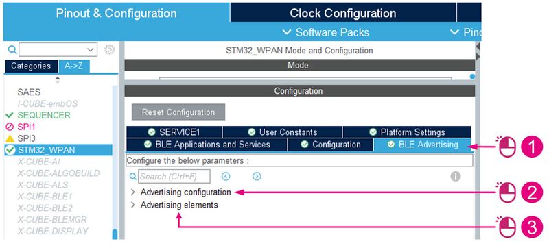
The advertising parameters are defined in the BLE Advertising tab:
| STM32_WPAN interface: BLE Advertising tab |
|---|
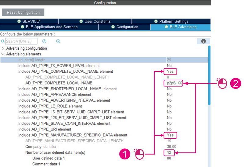
OpenAdvertising elements, included in the advertising packet payload, and:
| STM32_WPAN interface: advertising elements |
|---|
The generated code corresponding to the advertising packet elements is located in the app_ble.c file.
/**
 * Advertising Data
 */
uint8_t a_AdvData[25] =
{
  8, AD_TYPE_COMPLETE_LOCAL_NAME, 'p', '2', 'p', 'S', '_', 'X', 'X',  /* Complete name */
  15, AD_TYPE_MANUFACTURER_SPECIFIC_DATA, 0x30, 0x00, 0x00 /*  */, 0x00 /*  */, 0x00 /*  */, 0x00 /*  */, 0x00 /*  */, 0x00 /*  */, 0x00 /*  */, 0x00 /*  */, 0x00 /*  */, 0x00 /*  */, 0x00 /*  */, 0x00 /*  */,
};
In this example, we configure 2 advertising elements (advertising packet structure length = 25 bytes):
- Complete local name
- Manufacturer-specific data
The advertising information is represented by the advertising data elements, which are standardized on the Bluetooth SIG.
The manufacturer-specific data are updated at runtime (specific function in the app_ble.c file). More details are available here: BlueST SDK v2
5.2. Service and characteristic definition
All created services and characteristics are managed in an associated xxx.c file (one file per service; xxx = service short name, defined in the SERVICEx panel). Each service and characteristic is added with the XXX_Init(void) function (XXX = service short name (capitalized), defined in the SERVICEx panel), using :
- aci_gatt_add_service(…) for services.
- aci_gatt_add_char(…) for characteristics.
5.2.1. BLE Applications and Services tab
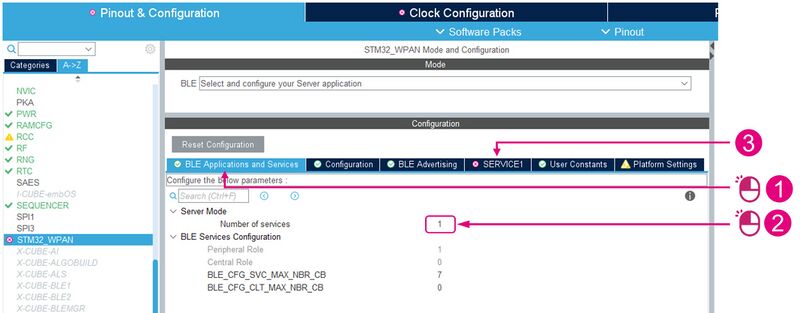
To start defining the Bluetooth® Low Energy application:
| BLE Applications and Services tab |
|---|
5.2.2. Service definition
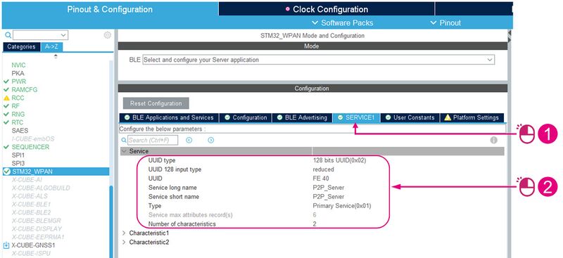
Each service has to be configured in a dedicated tab (named SERVICE1 to SERVICE25).
- Up to 25 characteristics per service
- UUID type can be defined as 16 or 128 bits, full or reduced
- UUID definition
- Type value is primary or secondary service
Once the number of services has been defined (in this example, we defined only one service with two characteristics), update the service information:
| Service definition |
|---|
5.2.3. Characteristic definition
For each characteristic, the following parameters must be defined:
- General
- Properties
- Permissions
- GATT events
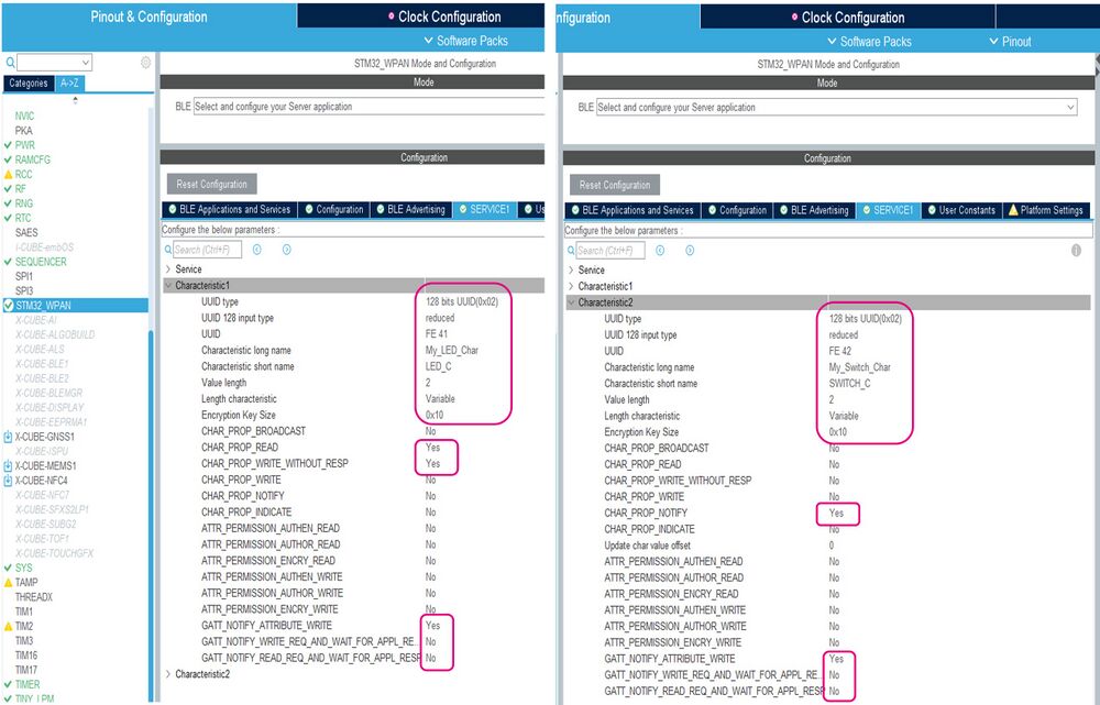
In our example, the service we defined has the following 2 characteristics:
| Characteristic 1 | Characteristic 2 | ||||
|---|---|---|---|---|---|
| UUID type | 128 bits UUID (0x02) | 128 bits UUID (0x02) | |||
| UUID 128 Input type | Reduced | Reduced | |||
| UUID | FE 41 | FE 42 | |||
| Characteristic long name | My_LED_Char | My_Switch_Char | |||
| Characteristic Short Name | LED_C | SWITCH_C | |||
| Value length | 2 | 2 | |||
| Length characteristic | Variable | Variable | |||
| Encryption key size | 0x10 | 0x10 | |||
| Char Properties | READ | WRITE_WITHOUT_RESP | NOTIFY | ||
| GATT events | GATT_NOTIFY_ATTRIBUTE_WRITE | GATT_NOTIFY_ATTRIBUTE_WRITE | |||
These characteristics have to be defined as shown in the image below:
| SERVICE1 characteristic definition |
|---|
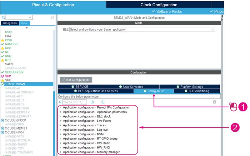
5.3. Application configuration
All application configuration topics are reachable by:
| Application configuration (1/12) |
|---|
For the next parts, it is recommended you keep the default values.
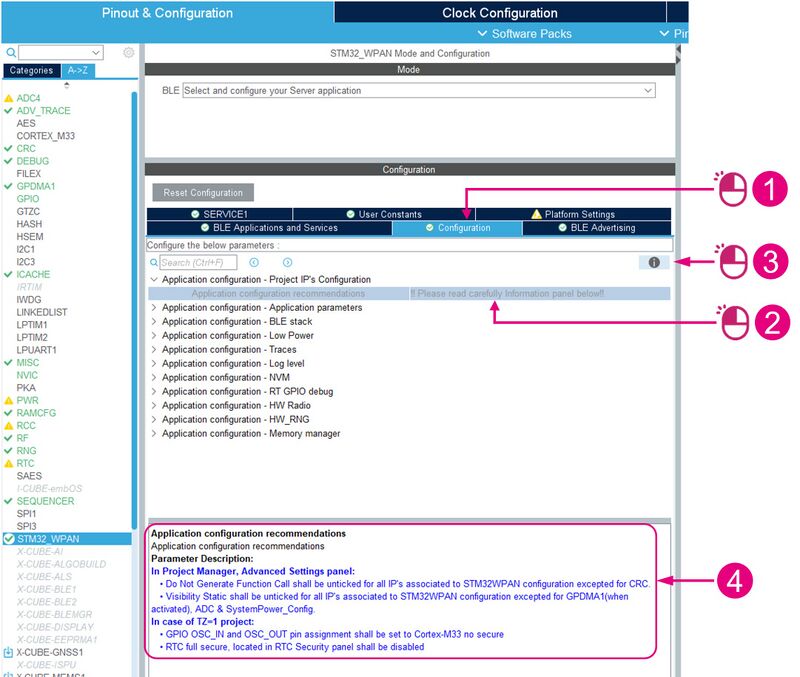
5.3.1. Project IP configuration
To display the application configuration recommendations:
| Application configuration (2/12) |
|---|
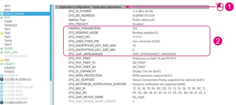
5.3.2. BLE Security
Pairing is done to support a secure connection method.
All parameters defined in this chapter are located in the app_conf.h file.
| Application configuration (3/12) |
|---|
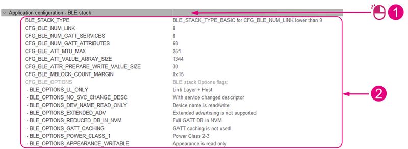
5.3.3. BLE stack
| Application configuration (4/12) |
|---|
5.3.4. Low power
| Application configuration (5/12) |
|---|
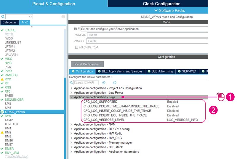
5.3.5. Logs
| Application configuration (7/12) |
|---|
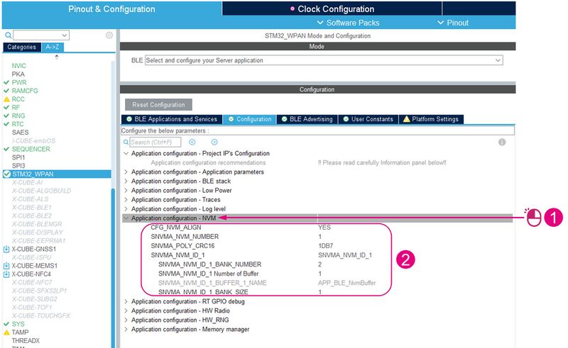
5.3.6. NVM
| Application configuration (8/12) |
|---|
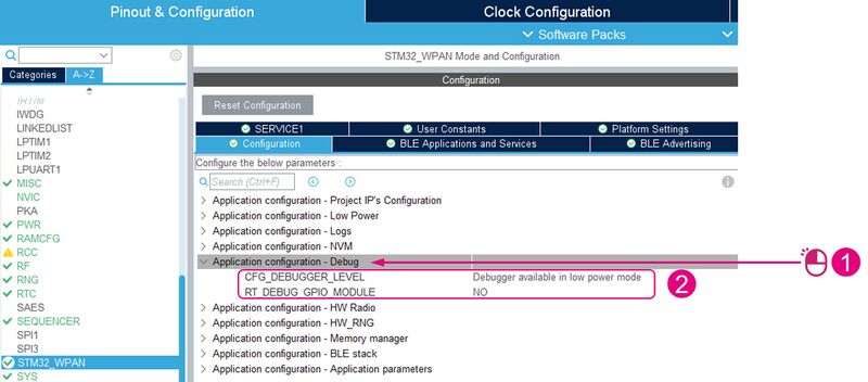
5.3.7. RT GPIO debug
| Application configuration (9/12) |
|---|
5.3.8. HW radio
| Application configuration (10/12) |
|---|
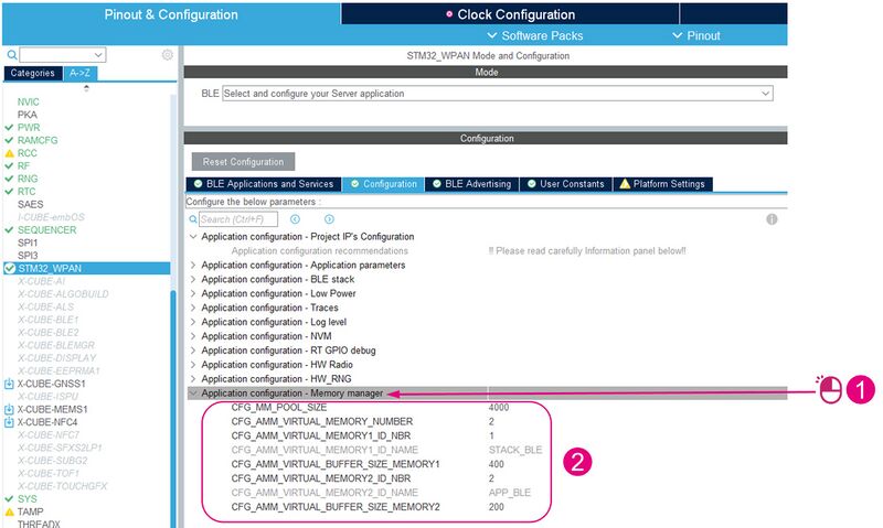
5.3.9. Memory manager
| Application configuration (12/12) |
|---|
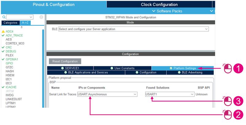
5.4. Platform settings
To change the BSP settings:
| Platform settings |
|---|
6. Project configuration
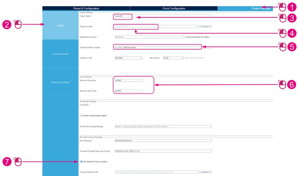
The Project Manager tab, which is used for the configuration of the project, has three main sections:
- Project
- Code Generator
- Advanced Settings
To configure your project, proceed as follows:
Depending on your work organization, you can choose not to use the default firmware location. In this case:
| Project configuration (1/4) |
|---|
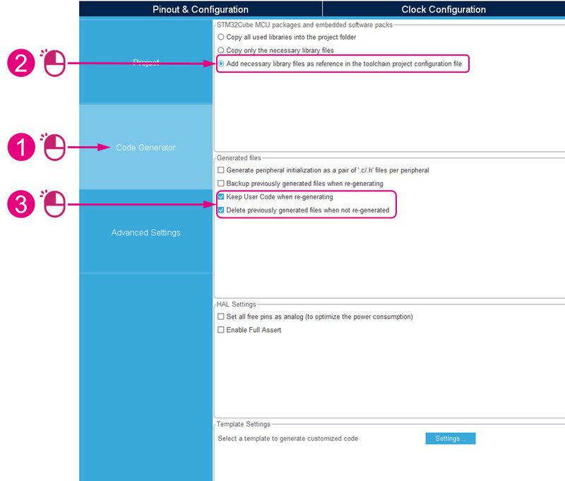
The Code Generator section lets you manage files, packages, and embedded software packs.
| Project configuration (2/4) |
|---|
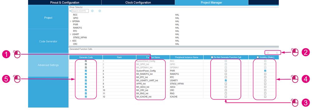
In the Advanced Settings section, rearrange the order of the functions:
| Project configuration (3/4) |
|---|
Still in the Advanced Settings section:
- The Do Not Generate Function Call checkbox must be unchecked for all IPs associated with the STM32WPAN configuration, except for CRC.
- The Visibility Static checkbox must be unchecked for all IPs associated with the STM32WPAN configuration, except for GPDMA (when activated), ADC, and SystemPower_Config.
- The Generate Code checkbox must be checked for all functions.
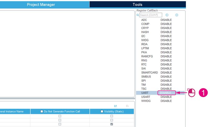
Then set UART to ENABLE in the Register Callback panel:
| Project configuration (4/4) |
|---|
7. P2P server notification and write management
In order to use the P2P server notification and write characteristics, several elements have to be configured:
- The user button and the related interrupt, to notify the P2P client.
- The blue LED, to receive a P2P client write operation.
- The custom application code, to manage B1 and write operations on the P2P server service.
| STM32WBA Nucleo board |
|---|
7.1. User button and LED pinout
Nucleo board pinout configuration:
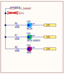
- Blue LED: PB4
- Red LED: PB8
- Green LED: PA9
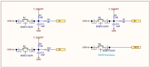
Switch (user button) pinout configuration:
- B1: PC13
- B2: PB6
- B3: PB7
For more information about button use cases for the P2P server application,
click here.
When used:
- The switch pins are declared as GPIO_EXTIx (x = pin number).
- The LED pins are declared as GPIO_OUTPUT.
7.2. LED and button setup
To configure the buttons and LEDs in this example, we will use the BSP files that we will include in the project at the end of this wikipage.
8. Code generation
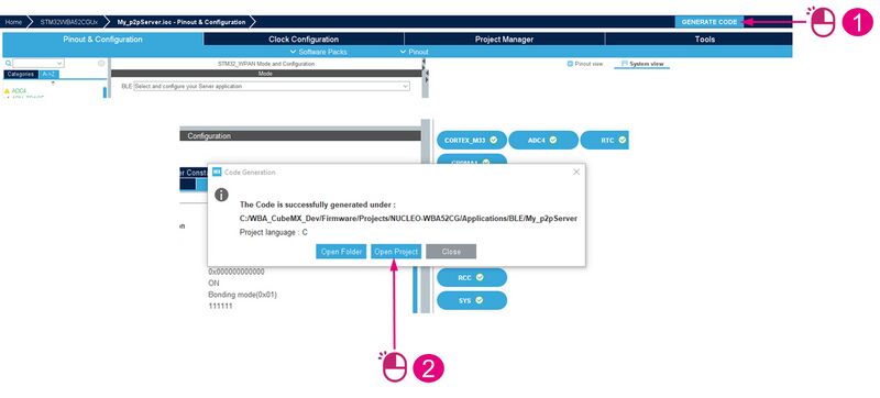
When you're done configuring your application, you can use STM32CubeMX to generate your code:
| Code generation |
|---|
9. Code modification: user sections
Once your button and LED GPIOs have been configured, generate your project by following the steps described in the Code Generation chapter.
The generated source code contains several sections called user sections, where users can add custom application code parts.
These sections are not erased/modified during project regeneration by STM32CubeMX.
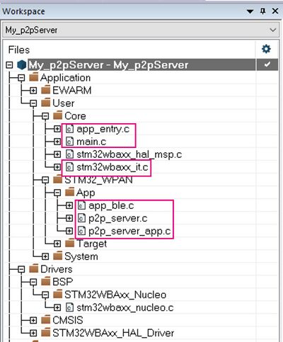
In order to manage notify and write operations on the P2P server service, some code parts have to be added to the user sections of the following files and their respective header files:
| Files to update |
|---|
- app_conf.h:
In app_conf.h, define the tasks for buttons, notifications, and advertising by adding code to the CFG_Task_Id_t user code section:
  /* USER CODE BEGIN CFG_Task_Id_t */
  CFG_TASK_BUTTON_B1,
  CFG_TASK_BUTTON_B2,
  CFG_TASK_BUTTON_B3,
  CFG_TASK_ADV_CANCEL_ID,
  CFG_TASK_SEND_NOTIF_ID,
  /* USER CODE END CFG_Task_Id_t */
You also need to update the user code defines to support the LEDs, buttons, and debug:
/* USER CODE BEGIN Defines */
/**
 * User interaction
 * When CFG_LED_SUPPORTED is set, LEDS are activated if requested
 * When CFG_BUTTON_SUPPORTED is set, the push button are activated if requested
 */

#define CFG_LED_SUPPORTED                       (1)
#define CFG_BUTTON_SUPPORTED                    (1)

/**
 * Overwrite some configuration imposed by Low Power level selected.
 */
#if (CFG_LPM_LEVEL > 1)
  #if CFG_LED_SUPPORTED
    #undef  CFG_LED_SUPPORTED
    #define CFG_LED_SUPPORTED      (0)
  #endif /* CFG_LED_SUPPORTED */
#endif /* CFG_LPM_LEVEL */

/* USER CODE END Defines */
- main.c:
  /* USER CODE BEGIN RNG_Init 2 */
  /* Disable RNG peripheral and its RCC clock */
  HW_RNG_Disable( );
  /* USER CODE END RNG_Init 2 */
/* USER CODE BEGIN 6 */
  /* User can add his own implementation to report the file name and line number,
     ex: printf("Wrong parameters value: file %s on line %d\r\n", file, line) */
  Error_Handler();
/* USER CODE END 6 */
- stm32wbaxx_it.c:
/* USER CODE BEGIN Includes */
#include "app_bsp.h"
/* USER CODE END Includes */
/* USER CODE BEGIN 1 */
/**
  * @brief This function handles EXTI Line6 interrupt.
  */
void EXTI6_IRQHandler(void)
{
  BSP_PB_IRQHandler(B2);
}

/**
  * @brief This function handles EXTI Line7 interrupt.
  */
void EXTI7_IRQHandler(void)
{
  BSP_PB_IRQHandler(B3);
}

/**
  * @brief This function handles EXTI Line13 interrupt.
  */
void EXTI13_IRQHandler(void)
{
  BSP_PB_IRQHandler(B1);
}
- app_entry.h:
/* USER CODE BEGIN EC */
/******************************************************************************
 * Information Table
 *
 * Version
 * [0:3]   = Build - 0: Untracked - 15:Released - x: Tracked version
 * [4:7]   = branch - 0: Mass Market - x: ...
 * [8:15]  = Subversion
 * [16:23] = Version minor
 * [24:31] = Version major
 *
 ******************************************************************************/
#define CFG_FW_BUILD              (0)
#define CFG_FW_BRANCH             (0)
#define CFG_FW_SUBVERSION         (0)
#define CFG_FW_MINOR_VERSION      (6)
#define CFG_FW_MAJOR_VERSION      (1)
/* USER CODE END EC */
- app_entry.c:
/* USER CODE BEGIN Includes */
#include "app_bsp.h"
/* USER CODE END Includes */
  /* USER CODE BEGIN APPE_Init_1 */
#if (CFG_LED_SUPPORTED == 1)
  APP_BSP_LedInit();
#endif /* (CFG_LED_SUPPORTED == 1) */
#if (CFG_BUTTON_SUPPORTED == 1)
  APP_BSP_ButtonInit();
#endif /* (CFG_BUTTON_SUPPORTED == 1) */

  /* USER CODE END APPE_Init_1 */
/* USER CODE BEGIN APPE_Init_1 */
#if (CFG_LED_SUPPORTED == 1)
  Led_Init();
#endif
#if (CFG_BUTTON_SUPPORTED == 1)
  Button_Init();
#endif
/* USER CODE END APPE_Init_1 */
- app_ble.h:
/* USER CODE BEGIN EC */
/**
  * ST Manufacturer ID
**/
#define ST_MANUF_ID  0x30

/**
  * BlueSTSDK Version
**/
enum
{
  BLUESTSDK_V1 =  0x01,
  BLUESTSDK_V2 =  0x02
};

/**
  * BOARD ID
**/
enum
{
  BOARD_ID_NUCLEO_WBA5X =  0x8B,
  BOARD_ID_DK_WBA5X     =  0x8C,
  BOARD_ID_NUCLEO_WBA6X =  0x8E
};

/**
  * FIRMWARE ID
**/
enum
{
  FW_ID_P2P_SERVER =  0x83,
  FW_ID_P2P_ROUTER =  0x85,
  FW_ID_DT_SERVER  =  0x88,
  FW_ID_COC_PERIPH =  0x87,
  FW_ID_HEART_RATE =  0x89,
  FW_ID_HEALTH_THERMO = 0x8A
};
/* USER CODE END EC */
- app_ble.c:
/* USER CODE BEGIN Includes */
#include "app_bsp.h"
/* USER CODE END Includes */
/* USER CODE BEGIN PTD_1*/
/* Advertising timeout timerID*/
UTIL_TIMER_Object_t Advertising_mgr_timer_Id;
/* Led Timeout timerID */
UTIL_TIMER_Object_t SwitchOffGPIO_timer_Id;

uint8_t connIntervalFlag;
/* USER CODE END PTD_1 */
/* USER CODE BEGIN PD */
#define LED_ON_TIMEOUT_MS              (5)
#define ADV_TIMEOUT_MS                 (60 * 1000)
/* Device Info Characteristic UUID */
#define COPY_UUID_128(uuid_struct, uuid_15, uuid_14, uuid_13, uuid_12, uuid_11, uuid_10, uuid_9, uuid_8, uuid_7, uuid_6, uuid_5, uuid_4, uuid_3, uuid_2, uuid_1, uuid_0) \
do {\
    uuid_struct[0] = uuid_0; uuid_struct[1] = uuid_1; uuid_struct[2] = uuid_2; uuid_struct[3] = uuid_3; \
    uuid_struct[4] = uuid_4; uuid_struct[5] = uuid_5; uuid_struct[6] = uuid_6; uuid_struct[7] = uuid_7; \
    uuid_struct[8] = uuid_8; uuid_struct[9] = uuid_9; uuid_struct[10] = uuid_10; uuid_struct[11] = uuid_11; \
    uuid_struct[12] = uuid_12; uuid_struct[13] = uuid_13; uuid_struct[14] = uuid_14; uuid_struct[15] = uuid_15; \
}while(0)
#define COPY_DEVINFO_UUID(uuid_struct)       COPY_UUID_128(uuid_struct,0x00,0x00,0xfe,0x31,0x8e,0x22,0x45,0x41,0x9d,0x4c,0x21,0xed,0xae,0x82,0xed,0x19)

/* USER CODE END PD */
/* USER CODE BEGIN PV */
uint8_t a_GATT_DevInfoData[22];
/* USER CODE END PV */
/* USER CODE BEGIN PFP */
static void Adv_Cancel_Req(void *arg);
static void Adv_Cancel(void);
static void Switch_OFF_GPIO(void *arg);
static void fill_advData(uint8_t *p_adv_data, uint8_t tab_size, const uint8_t*p_bd_addr);
/* USER CODE END PFP */
/* USER CODE BEGIN APP_BLE_Init_1 */
  tBleStatus ret;
/* USER CODE END APP_BLE_Init_1 */
/* USER CODE BEGIN APP_BLE_Init_4 */
    UTIL_SEQ_RegTask(1<<CFG_TASK_ADV_CANCEL_ID, UTIL_SEQ_RFU, Adv_Cancel);

    /* Create timer to handle the Advertising Stop */
    UTIL_TIMER_Create(&(bleAppContext.Advertising_mgr_timer_Id),
                      0,
                      UTIL_TIMER_ONESHOT,
                      &Adv_Cancel_Req,
                      0);
    /* Create timer to handle the Led Switch OFF */
    UTIL_TIMER_Create(&(bleAppContext.SwitchOffGPIO_timer_Id),
                      0,
                      UTIL_TIMER_ONESHOT,
                      &Switch_OFF_GPIO,
                      0);
 /* USER CODE END APP_BLE_Init_4 */
/* USER CODE BEGIN APP_BLE_Init_3 */
    ret = aci_hal_set_radio_activity_mask(0x0006);
    if (ret != BLE_STATUS_SUCCESS)
    {
      LOG_INFO_APP("  Fail   : aci_hal_set_radio_activity_mask command, result: 0x%2X\n", ret);
    }
    else
    {
      LOG_INFO_APP("  Success: aci_hal_set_radio_activity_mask command\n\r");
    }

    /* Start to Advertise to accept a connection */
    APP_BLE_Procedure_Gap_Peripheral(PROC_GAP_PERIPH_ADVERTISE_START_FAST);

    /* Start a timer to stop advertising after a while */
    UTIL_TIMER_StartWithPeriod(&bleAppContext.Advertising_mgr_timer_Id, ADV_TIMEOUT_MS);

/* USER CODE END APP_BLE_Init_3 */
/* USER CODE BEGIN APP_BLE_Init_2 */
bleAppContext.connIntervalFlag = 0;
/* USER CODE END APP_BLE_Init_2 */
/* USER CODE BEGIN EVT_DISCONN_COMPLETE */
APP_BLE_Procedure_Gap_Peripheral(PROC_GAP_PERIPH_ADVERTISE_START_FAST);
UTIL_TIMER_StartWithPeriod(&bleAppContext.Advertising_mgr_timer_Id, ADV_TIMEOUT_MS);
/* USER CODE END EVT_DISCONN_COMPLETE */
/* USER CODE BEGIN HCI_EVT_LE_ENHANCED_CONN_COMPLETE */
/* The connection is done, there is no need anymore to schedule the LP ADV */
UTIL_TIMER_Stop(&(bleAppContext.Advertising_mgr_timer_Id));
/* USER CODE END HCI_EVT_LE_ENHANCED_CONN_COMPLETE */
/* USER CODE BEGIN HCI_EVT_LE_CONN_COMPLETE */
/* The connection is done, there is no need anymore to schedule the LP ADV */
UTIL_TIMER_Stop(&(bleAppContext.Advertising_mgr_timer_Id));
/* USER CODE END HCI_EVT_LE_CONN_COMPLETE */
/* USER CODE BEGIN RADIO_ACTIVITY_EVENT*/
#if (CFG_LED_SUPPORTED == 1)
BSP_LED_On(LED_GREEN);
#endif
UTIL_TIMER_StartWithPeriod(&bleAppContext.SwitchOffGPIO_timer_Id, LED_ON_TIMEOUT_MS);
/* USER CODE END RADIO_ACTIVITY_EVENT*/
/* USER CODE BEGIN CONN_PARAM_UPDATE */
if (bleAppContext.connIntervalFlag != 0)
{
 bleAppContext.connIntervalFlag = 0;
 paramA = CONN_INT_MS(50);
 paramB = CONN_INT_MS(50);
}
else
{
 bleAppContext.connIntervalFlag = 1;
 paramA = CONN_INT_MS(1000);
 paramB = CONN_INT_MS(1000);
}
/* USER CODE END CONN_PARAM_UPDATE */
  /* USER CODE BEGIN Ble_Hci_Gap_Gatt_Init */
/* Add number of record for Device Info Characteristic */
  static const uint8_t p_additional_svc_record[1] = {0x03};

  ret = aci_hal_write_config_data(CONFIG_DATA_GAP_ADD_REC_NBR_OFFSET,
                                  CONFIG_DATA_GAP_ADD_REC_NBR_LEN,
                                  (uint8_t*) p_additional_svc_record);
  if (ret != BLE_STATUS_SUCCESS)
  {
    LOG_INFO_APP("  Fail   : aci_hal_write_config_data command - CONFIG_DATA_GAP_ADD_REC_NBR_OFFSET, result: 0x%02X\n", ret);
  }
  else
  {
    LOG_INFO_APP("  Success: aci_hal_write_config_data command - CONFIG_DATA_GAP_ADD_REC_NBR_OFFSET\n");
  }
  /* USER CODE END Ble_Hci_Gap_Gatt_Init */
  /* USER CODE BEGIN Ble_Hci_Gap_Gatt_Init_1*/
  fill_advData(&a_AdvData[0], sizeof(a_AdvData), (uint8_t*) p_bd_addr);
  /* USER CODE END Ble_Hci_Gap_Gatt_Init_1*/
  /* USER CODE BEGIN Ble_Hci_Gap_Gatt_Init_2 */
  /** Device Info Characteristic **/
  /* Add a new characterisitc */
  Char_UUID_t  uuid;
  uint16_t gap_DevInfoChar_handle = 0U;

  /* Add new characteristic to GAP service */
  uint16_t SizeDeviceInfoChar = 22;
  COPY_DEVINFO_UUID(uuid.Char_UUID_128);

  ret = aci_gatt_add_char(gap_service_handle,
                          UUID_TYPE_128,
                          (Char_UUID_t *) &uuid,
                          SizeDeviceInfoChar,
                          CHAR_PROP_READ,
                          ATTR_PERMISSION_NONE,
                          GATT_DONT_NOTIFY_EVENTS,
                          0x10,
                          CHAR_VALUE_LEN_CONSTANT,
                          &gap_DevInfoChar_handle);
  if (ret != BLE_STATUS_SUCCESS)
  {
    LOG_INFO_APP("  Fail   : aci_gatt_add_char command : Device Info Char, error code: 0x%2X\n", ret);
  }
  else
  {
    LOG_INFO_APP("  Success: aci_gatt_add_char command : Device Info Char\n");
  }

  /**
  * Initialize Device Info Characteristic
  */
  uint8_t * p_device_info_payload = (uint8_t*)a_GATT_DevInfoData;

  LOG_INFO_APP("---------------------------------------------\n");
  /* Device ID: WBA5x, WBA6x... */
  a_GATT_DevInfoData[0] = (uint8_t)(LL_DBGMCU_GetDeviceID() & 0xff);
  a_GATT_DevInfoData[1] = (uint8_t)((LL_DBGMCU_GetDeviceID() & 0xff00)>>8);
  LOG_INFO_APP("-- DEVICE INFO CHAR : Device ID = 0x%02X %02X\n",a_GATT_DevInfoData[1],a_GATT_DevInfoData[0]);

  /* Rev ID: RevA, RevB... */
  a_GATT_DevInfoData[2] = (uint8_t)(LL_DBGMCU_GetRevisionID() & 0xff);
  a_GATT_DevInfoData[3] = (uint8_t)((LL_DBGMCU_GetRevisionID() & 0xff00)>>8);
  LOG_INFO_APP("-- DEVICE INFO CHAR : Revision ID = 0x%02X %02X\n",a_GATT_DevInfoData[3],a_GATT_DevInfoData[2]);

  /* Board ID: Nucleo WBA, DK1 WBA... */
  a_GATT_DevInfoData[4] = BOARD_ID_NUCLEO_WBA5X;
  LOG_INFO_APP("-- DEVICE INFO CHAR : Board ID = 0x%02X\n",a_GATT_DevInfoData[4]);

  /* HW Package: QFN32, QFN48... */
  a_GATT_DevInfoData[5] = (uint8_t)LL_GetPackageType();
  LOG_INFO_APP("-- DEVICE INFO CHAR : HW Package = 0x%02X\n",a_GATT_DevInfoData[5]);

  /* FW version: v1.3.0, v1.4.0... */
  a_GATT_DevInfoData[6] = CFG_FW_MAJOR_VERSION;
  a_GATT_DevInfoData[7] = CFG_FW_MINOR_VERSION;
  a_GATT_DevInfoData[8] = CFG_FW_SUBVERSION;
  a_GATT_DevInfoData[9] = CFG_FW_BRANCH;
  a_GATT_DevInfoData[10] = CFG_FW_BUILD;
  LOG_INFO_APP("-- DEVICE INFO CHAR : FW Version = v%d.%d.%d - branch %d - build %d\n",a_GATT_DevInfoData[6],a_GATT_DevInfoData[7],a_GATT_DevInfoData[8],a_GATT_DevInfoData[9],a_GATT_DevInfoData[10]);

  /* Application ID: p2pServer, HeartRate... */
  a_GATT_DevInfoData[11] = FW_ID_P2P_SERVER;
  LOG_INFO_APP("-- DEVICE INFO CHAR : Application ID = 0x%02X\n",a_GATT_DevInfoData[11]);

  /* Host Stack Version: 0.15, 0.16... */
  uint8_t HCI_Version = 0;
  uint16_t HCI_Subversion = 0;
  uint8_t LMP_Version = 0;
  uint16_t Company_Identifier = 0;
  uint16_t LMP_Subversion = 0;
  hci_read_local_version_information(&HCI_Version, &HCI_Subversion, &LMP_Version, &Company_Identifier, &LMP_Subversion);
  a_GATT_DevInfoData[12] = (uint8_t)((uint16_t)HCI_Subversion & 0xff);
  LOG_INFO_APP("-- DEVICE INFO CHAR : Host Stack version = 0x%02X\n",a_GATT_DevInfoData[12]);

  /* Host Stack Type: Full, Basic, Basic Plus... */
  a_GATT_DevInfoData[13] = (uint8_t)(((uint16_t)HCI_Subversion & 0xff00)>>8);
  LOG_INFO_APP("-- DEVICE INFO CHAR : Host Stack Type = 0x%02X\n",a_GATT_DevInfoData[13]);

  /* RESERVED */
  a_GATT_DevInfoData[14] = 0xFF; /* reserved */
  a_GATT_DevInfoData[15] = 0xFF; /* reserved */
  a_GATT_DevInfoData[16] = 0xFF; /* reserved */
  a_GATT_DevInfoData[17] = 0xFF; /* reserved */

  /* Audio Lib */
  a_GATT_DevInfoData[18] = 0xFF; /* NA */
  a_GATT_DevInfoData[19] = 0xFF; /* NA */

  /* Audio Codec */
  a_GATT_DevInfoData[20] = 0xFF; /* NA */
  a_GATT_DevInfoData[21] = 0xFF; /* NA */
  LOG_INFO_APP("---------------------------------------------\n");

  ret = aci_gatt_update_char_value(gap_service_handle,
                             gap_DevInfoChar_handle,
                             0, /* charValOffset */
                             SizeDeviceInfoChar, /* charValueLen */
                             p_device_info_payload);
  if (ret != BLE_STATUS_SUCCESS)
  {
    LOG_INFO_APP("  Fail   : aci_gatt_update_char_value DEVINFO command, error code: 0x%2X\n", ret);
  }
  else
  {
    LOG_INFO_APP("  Success: aci_gatt_update_char_value DEVINFO command\n");
  }
  /* USER CODE END Ble_Hci_Gap_Gatt_Init_2 */
/* USER CODE BEGIN FD_LOCAL_FUNCTION */

static void Adv_Cancel_Req(void *arg)
{
  UTIL_SEQ_SetTask(1 << CFG_TASK_ADV_CANCEL_ID, CFG_SEQ_PRIO_0);
  return;
}

static void Switch_OFF_GPIO(void *arg)
{
  #if (CFG_LED_SUPPORTED == 1)
  BSP_LED_Off(LED_GREEN);
  #endif
  return;
}

static void Adv_Cancel(void)
{
  #if (CFG_LED_SUPPORTED == 1)
  BSP_LED_Off(LED_GREEN);
  #endif

  APP_BLE_Procedure_Gap_Peripheral(PROC_GAP_PERIPH_ADVERTISE_STOP);

  return;
}

static void fill_advData(uint8_t *p_adv_data, uint8_t tab_size, const uint8_t* p_bd_addr)
{
  uint16_t i =0;
  uint8_t bd_addr_1, bd_addr_0;
  uint8_t ad_length, ad_type;

  while(i < tab_size)
  {
    ad_length = p_adv_data[i];
    ad_type = p_adv_data[i + 1];

    switch (ad_type)
    {
    case AD_TYPE_FLAGS:
      break;
    case AD_TYPE_TX_POWER_LEVEL:
      break;
    case AD_TYPE_COMPLETE_LOCAL_NAME:
      {
        if((p_adv_data[i + ad_length] == 'X') && (p_adv_data[i + ad_length - 1] == 'X'))
        {
          bd_addr_1 = ((p_bd_addr[0] & 0xF0)>>4);
          bd_addr_0 = (p_bd_addr[0] & 0xF);

          /* Convert hex value into ascii */
          if(bd_addr_1 > 0x09)
          {
            p_adv_data[i + ad_length - 1] = bd_addr_1 + '7';
          }
          else
          {
            p_adv_data[i + ad_length - 1] = bd_addr_1 + '0';
          }

          if(bd_addr_0 > 0x09)
          {
            p_adv_data[i + ad_length] = bd_addr_0 + '7';
          }
          else
          {
            p_adv_data[i + ad_length] = bd_addr_0 + '0';
          }
        }
        break;
      }
    case AD_TYPE_MANUFACTURER_SPECIFIC_DATA:
      {
        p_adv_data[i+2] = ST_MANUF_ID;
        p_adv_data[i+3] = 0x00;
        p_adv_data[i+4] = BLUESTSDK_V2; /* blueST SDK version */
        p_adv_data[i+5] = BOARD_ID_NUCLEO_WBA5X; /* Board ID */
        p_adv_data[i+6] = FW_ID_P2P_SERVER; /* FW ID */
        p_adv_data[i+7] = 0x00; /* FW data 1 */
        p_adv_data[i+8] = 0x00; /* FW data 2 */
        p_adv_data[i+9] = 0x00; /* FW data 3 */
        p_adv_data[i+10] = p_bd_addr[5]; /* MSB BD address */
        p_adv_data[i+11] = p_bd_addr[4];
        p_adv_data[i+12] = p_bd_addr[3];
        p_adv_data[i+13] = p_bd_addr[2];
        p_adv_data[i+14] = p_bd_addr[1];
        p_adv_data[i+15] = p_bd_addr[0]; /* LSB BD address */
        break;
      }
    default:
      break;
    }
    i += ad_length + 1; /* increment the iterator to go on next element*/
  }
}
/* USER CODE END FD_LOCAL_FUNCTION */
/* USER CODE BEGIN FD_WRAP_FUNCTIONS */
#if (CFG_BUTTON_SUPPORTED == 1)
void APP_BSP_Button1Action(void)
{
  if (bleAppContext.Device_Connection_Status == APP_BLE_IDLE)
  {
    /* Relaunch advertising */
    APP_BLE_Procedure_Gap_Peripheral(PROC_GAP_PERIPH_ADVERTISE_START_FAST);
    UTIL_TIMER_StartWithPeriod(&bleAppContext.Advertising_mgr_timer_Id, ADV_TIMEOUT_MS);
  }
  else
  {
    UTIL_SEQ_SetTask( 1<<CFG_TASK_SEND_NOTIF_ID, CFG_SEQ_PRIO_0);
  }
  return;
}

void APP_BSP_Button2Action(void)
{
  tBleStatus ret;

  if (bleAppContext.Device_Connection_Status != APP_BLE_CONNECTED_SERVER)
  {
    /* Clear Security Database */
    ret = aci_gap_clear_security_db();
    if (ret != BLE_STATUS_SUCCESS)
    {
      LOG_INFO_APP("==>> aci_gap_clear_security_db - Fail, result: 0x%02X\n", ret);
    }
    else
    {
      LOG_INFO_APP("==>> aci_gap_clear_security_db - Success\n");
    }
  }
  else
  {
    /* Launch advertising for multi connection */
    APP_BLE_Procedure_Gap_Peripheral(PROC_GAP_PERIPH_ADVERTISE_START_FAST);
    UTIL_TIMER_StartWithPeriod(&bleAppContext.Advertising_mgr_timer_Id, ADV_TIMEOUT_MS);
  }

  return;
}

void APP_BSP_Button3Action(void)
{
  if (bleAppContext.Device_Connection_Status != APP_BLE_CONNECTED_SERVER)
  {

  }
  else
  {
    APP_BLE_Procedure_Gap_Peripheral(PROC_GAP_PERIPH_CONN_PARAM_UPDATE);
  }

  return;
}
#endif
/* USER CODE END FD_WRAP_FUNCTIONS */
- p2p_server.c:
/* USER CODE BEGIN Service1_Char_1_ACI_GATT_ATTRIBUTE_MODIFIED_VSEVT_CODE */
LOG_INFO_APP("-- GATT : LED CONFIGURATION RECEIVED\n");
notification.DataTransfered.Length = p_attribute_modified->Attr_Data_Length;
notification.DataTransfered.p_Payload = p_attribute_modified->Attr_Data;
/* USER CODE END Service1_Char_1_ACI_GATT_ATTRIBUTE_MODIFIED_VSEVT_CODE */
/* USER CODE BEGIN BLECORE_EVT */
/* Manage ACI_GATT_INDICATION_VSEVT_CODE occurring on Android 12 */
case ACI_GATT_INDICATION_VSEVT_CODE:
{
  tBleStatus status = BLE_STATUS_FAILED;
  aci_gatt_indication_event_rp0 *pr = (void*)p_blecore_evt->data;
  status = aci_gatt_confirm_indication(pr->Connection_Handle);
  if (status != BLE_STATUS_SUCCESS)
  {
    LOG_INFO_APP("  Fail   : aci_gatt_confirm_indication command, result: 0x%x \n", status);
  }
  else
  {
    LOG_INFO_APP("  Success: aci_gatt_confirm_indication command\n");
  }
}
  break; /* end ACI_GATT_NOTIFICATION_VSEVT_CODE */
/* USER CODE END BLECORE_EVT */
- p2p_server_app.c:
/* USER CODE BEGIN Includes */
#include "app_bsp.h"
/* USER CODE END Includes */
/* USER CODE BEGIN PTD */
 typedef struct{
    uint8_t             Device_Led_Selection;
    uint8_t             Led1;
 }P2P_LedCharValue_t;

 typedef struct{
    uint8_t             Device_Button_Selection;
    uint8_t             ButtonStatus;
 }P2P_ButtonCharValue_t;
/* USER CODE END PTD */
/* USER CODE BEGIN Service1_APP_Context_t */
  P2P_LedCharValue_t              LedControl;
  P2P_ButtonCharValue_t           ButtonControl;
/* USER CODE END Service1_APP_Context_t */
/* USER CODE BEGIN PFP */
static void P2P_SERVER_APP_LED_BUTTON_context_Init(void);
/* USER CODE END PFP */
/* USER CODE BEGIN Service1Char1_WRITE_NO_RESP_EVT */
if(p_Notification->DataTransfered.p_Payload[1] == 0x01)
{
#if (CFG_LED_SUPPORTED == 1)
  BSP_LED_On(LED_BLUE);
#endif
  LOG_INFO_APP("-- P2P APPLICATION SERVER : LED1 ON\n");
  P2P_SERVER_APP_Context.LedControl.Led1 = 0x01; /* LED1 ON */
}
if(p_Notification->DataTransfered.p_Payload[1] == 0x00)
{
#if (CFG_LED_SUPPORTED == 1)
  BSP_LED_Off(LED_BLUE);
#endif
  LOG_INFO_APP("-- P2P APPLICATION SERVER : LED1 OFF\n");
}
P2P_SERVER_APP_Context.LedControl.Led1 = 0x00; /* LED1 OFF */
/* USER CODE END Service1Char1_WRITE_NO_RESP_EVT */
/* USER CODE BEGIN Service1Char2_NOTIFY_ENABLED_EVT */
P2P_SERVER_APP_Context.Switch_c_Notification_Status = Switch_c_NOTIFICATION_ON;
LOG_INFO_APP("-- P2P APPLICATION SERVER : NOTIFICATION ENABLED\n");
LOG_INFO_APP(" \n\r");
/* USER CODE END Service1Char2_NOTIFY_ENABLED_EVT */
/* USER CODE BEGIN Service1Char2_NOTIFY_DISABLED_EVT */
P2P_SERVER_APP_Context.Switch_c_Notification_Status = Switch_c_NOTIFICATION_OFF;
LOG_INFO_APP("-- P2P APPLICATION SERVER : NOTIFICATION DISABLED\n");
LOG_INFO_APP(" \n\r");
/* USER CODE END Service1Char2_NOTIFY_DISABLED_EVT */
/* USER CODE BEGIN Service1_APP_DISCON_HANDLE_EVT */
P2P_SERVER_APP_LED_BUTTON_context_Init();
/* USER CODE END Service1_APP_DISCON_HANDLE_EVT */
/* USER CODE BEGIN Service1_APP_Init */
UTIL_SEQ_RegTask( 1U << CFG_TASK_SEND_NOTIF_ID, UTIL_SEQ_RFU, P2P_SERVER_Switch_c_SendNotification);

/**
* Initialize LedButton Service
*/
P2P_SERVER_APP_Context.Switch_c_Notification_Status= Switch_c_NOTIFICATION_OFF;
P2P_SERVER_APP_LED_BUTTON_context_Init();/* USER CODE END Service1_APP_Init */
/* USER CODE BEGIN Service1Char2_NS_1 */

  if(P2P_SERVER_APP_Context.ButtonControl.ButtonStatus == 0x00)
  {
    P2P_SERVER_APP_Context.ButtonControl.ButtonStatus = 0x01;
  }
  else
  {
    P2P_SERVER_APP_Context.ButtonControl.ButtonStatus = 0x00;
  }
  a_P2P_SERVER_UpdateCharData[0] = 0x01; /* Device Led selection */
  a_P2P_SERVER_UpdateCharData[1] = P2P_SERVER_APP_Context.ButtonControl.ButtonStatus;
  /* Update notification data length */
  p2p_server_notification_data.Length = (p2p_server_notification_data.Length) + 2;

  if(P2P_SERVER_APP_Context.Switch_c_Notification_Status == Switch_c_NOTIFICATION_ON)
  {
    LOG_INFO_APP("-- P2P APPLICATION SERVER : INFORM CLIENT BUTTON 1 PUSHED\n");
    notification_on_off = Switch_c_NOTIFICATION_ON;
  }
  else
  {
    LOG_INFO_APP("-- P2P APPLICATION SERVER : CAN'T INFORM CLIENT - NOTIFICATION DISABLED\n");
  }
  /* USER CODE END Service1Char2_NS_1 */
/* USER CODE BEGIN FD_LOCAL_FUNCTIONS */
static void P2P_SERVER_APP_LED_BUTTON_context_Init(void)
{
  #if (CFG_LED_SUPPORTED == 1)
  BSP_LED_Off(LED_BLUE);
  #endif
  P2P_SERVER_APP_Context.LedControl.Device_Led_Selection=0x01;        /* select device 01 */
  P2P_SERVER_APP_Context.LedControl.Led1=0x00;                        /* led OFF */
  P2P_SERVER_APP_Context.ButtonControl.Device_Button_Selection=0x01;  /* select device 01 */
  P2P_SERVER_APP_Context.ButtonControl.ButtonStatus=0x00;

  return;
}

/* USER CODE END FD_LOCAL_FUNCTIONS */
10. Inserting external files
To complete the creation of our P2P server project, we will now add the following external BSP files:
- app_bsp.c
- app_bsp.h
- stm32wbaxx_nucleo.c
- stm32wbaxx_nucleo.h
- stm32wbaxx_nucleo_conf.h
- stm32wbaxx_nucleo_errno.h
You can download the last 4 BSP STM32WBAXX-NUCLEO components here.
These files provide a set of firmware functions to manage the LEDs and push buttons available on the STM32WBAxx-Nucleo board.
Add the app_bsp.c and app_bsp.h files in your project folder: YourProject\STM32_WPAN\App.
Add the stm32wbaxx_nucleo.c and stm32wbaxx_nucleo.h files in your project folder: YourProject\Drivers\BSP\STM32WBAxx_Nucleo.
Then rename the stm32wbaxx_nucleo_conf_template.h file to stm32wbaxx_nucleo_conf.h.
Now, add stm32wbaxx_nucleo_conf.h and stm32wbaxx_nucleo_errno.h in your project folder (ServerMX\Core\Inc).
To add external code files, we recommend using the .extSettings file (For more details, visit UM1718 User Manual section 6.4.
The .extsettings file allows you to add additional settings which can be used when external tools call STM32CubeMX to generate the project and require specific project settings.
| .extSettings file |
|---|
Your .extSettings file should contain the following:
[ProjectFiles]
HeaderPath=..\Drivers\BSP\STM32WBAxx_Nucleo;

[Groups]
Drivers/BSP/STM32WBAxx_Nucleo=../Drivers/BSP/STM32WBAxx_Nucleo/stm32wbaxx_nucleo.c;
Application/User/STM32_WPAN/App=../STM32_WPAN/App/app_bsp.c;
The path in HeaderPath indicates where the stm32wbaxx_nucleo.h file is stored in your project. In Groups, you need to specify where you want the code file to appear in your workspace, and where it is stored.
After this, you can click Generate again in STM32CubeMX.
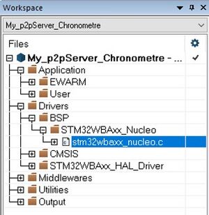
Your workspace should now look like this:
You have just finished creating a p2pServer application with STM32CubeMX starting from the STM32WBA55CGU6 chip.
You can find more information about peer-to-peer applications on STM32WBA Peer To Peer wiki article
11. Detail of BLE auto configuration for a Peripheral & GATT server application
Below are the steps performed automatically when configuring the STM32_WPAN BLE panel. (Performed in Automatic_configuration_for_a_BLE_project section)
11.1. RAMCFG
The RAMs ConFiGuration Controller (RAMCFG) configures the features of the internal SRAMs.
Activating an SRAM is mandatory for the application. We dynamically modify the RAM configuration (System Clock Manager (SCM) module). This allows us to manage cases where we use low power, for example.
| RAMCFG activation |
|---|
11.2. ICACHE
The Instruction CACHE (ICACHE) is introduced on the C-AHB code bus of the ARM Cortex-M33® processor to improve performance when fetching instructions and data from internal memories.
The ICACHE configuration is done as follows:
| ICACHE activation |
|---|
11.3. RNG
The Random Number Generator (RNG) provides the application with full entropy outputs as 32-bit samples. It is necessary to activate it, because the link layer regularly requests RNG.
| RNG activation |
|---|
| RNG activation |
|---|
11.4. RCC
Reset and Clock Control (RCC) manages the different kinds of reset and generates all clocks for the bus and peripherals.
| RCC activation & setup |
|---|
11.5. RF
Activating RF is mandatory to activate the link layer.
| RF activation |
|---|
11.6. RTC
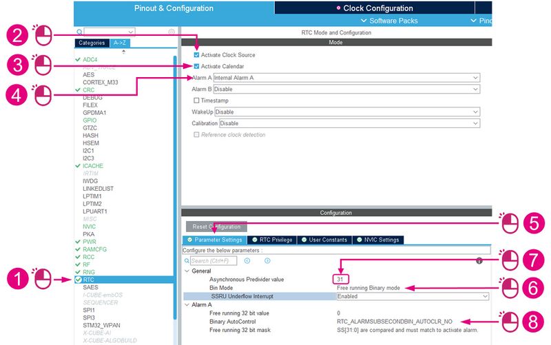
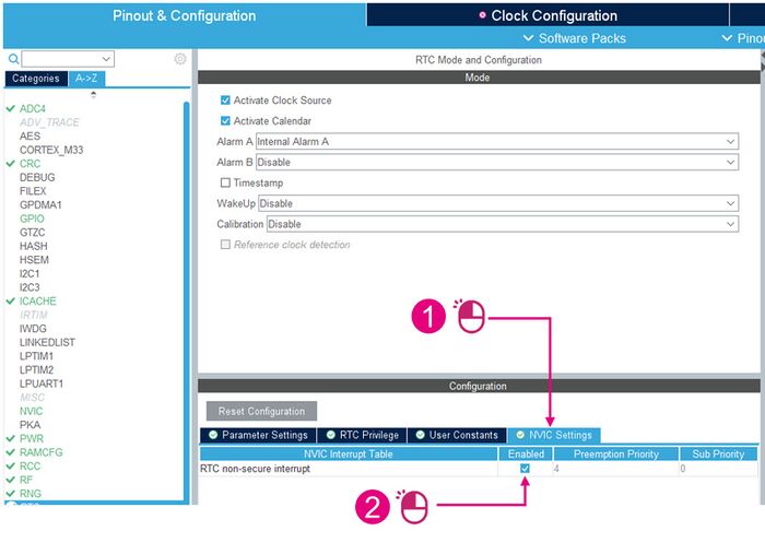
The Real Time Clock (RTC) provides an automatic wake-up to manage all low-power modes. The timers for the application, and those of the link layer deep sleep manager (PHY shutdown), are based on the timer server utility. This utility is based on the RTC.
First:
| RTC configuration (1/2) |
|---|
Then:
| RTC configuration (2/2) |
|---|
12. References
