1. Introduction
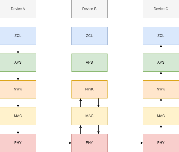
In Zigbee®, there are several layers in the stack, each with its own responsibilities. From highest to lowest there is ZCL, APS, NWK, MAC, and PHY. As a packet moves down the stack, each layer appends its header and/or trailer. The ZCL Layer has the smallest packet size being the highest layer. The PHY Layer has the largest packet size being the lowest layer. The ZCL Layer is the most familiar to the user as its packets are commands such as a Toggle Command defined in the ZCL Specification in order to toggle a light (or other) connected to a server within the Zigbee Network. The PHY Layer is the least familiar to the user as it is the final packet form to be transmitted on-air. The packet structure is nested as shown in the following diagram.
Multi-hop in Zigbee is a key feature that enables Mesh Networking. In Zigbee, Multi-hop is handled at the NWK Layer. Consequently, any Zigbee packet must follow the Multi-hop path below to arrive at its destination in the simplest use case, which includes three devices: one Source Node (Device A), one Relay Node (Device B), and one Destination Node (Device C).
2. Zigbee routing mechanisms
In Zigbee, there are three routing mechanisms: Table Routing, Source Routing, and Broadcast Routing (Multicast Routing is deprecated). The appropriate routing mechanism is chosen internally by the stack based on the following points:
- If the Destination Address is a broadcast address, use Broadcast Routing.
- Else, if Source Routing is available, use Source Routing.
- Else, if Table Routing is available, use Table Routing.
- If none of the above apply, try sending directly.
2.1. Table Routing
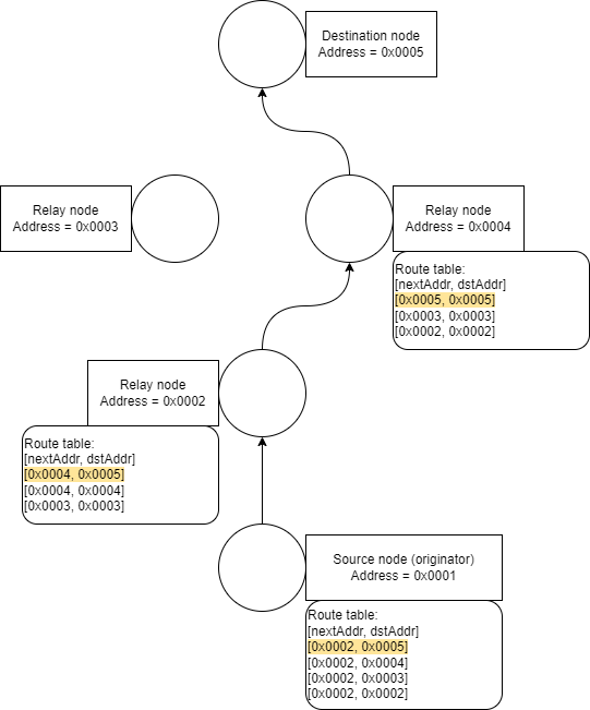
Table Routing is used when a packet has a Destination Address that is not a Broadcast Address (Unicast or Group Address), and when a Route Entry can be found in the Route Table of the Source Node. The route (list of addresses) followed by the packet is not known in advance of the first transmission. Each node contributes the Next Address in the route by searching its Route Table. Each Route Entry in the Route Table contains a Next Address (nextAddr), and Destination Address (dstAddr). The Route Table is automatically populated by the Route Discovery Procedure. See the Zigbee Specification "Initiation of Route Discovery" for more details.
In the following diagram, the packet follows the logic explained below:
- The packet starts at the Source Node with address
0x0001. - The Route Table provides the Next Address
0x0002to get to the Destination Node with address0x0005. - The packet is transmitted from the Source Node with address
0x0001to Relay Node with address0x0002. - The Route Table provides the Next Address
0x0004to get to the Destination Node with address0x0005. - The packet is transmitted from Relay Node with address
0x0002to Relay Node with address0x0004. - The Route Table provides the Next Address
0x0005to get to the Destination Node with address0x0005. - The packet is transmitted from Relay Node with address
0x0004to the Destination Node with address0x0005. - The packet finishes at the Destination Node with address
0x0005.
2.2. Source Routing
Source Routing is used when a packet has a Destination Address that is not a Broadcast Address (Unicast or Group Address), and when a Route Record can be found in the Route Record Table of the Source Node. This routing mechanism takes precedence over Table Routing. The route (list of addresses) followed by the packet is known in advance of the first transmission. The Source Node constructs a Source Route by searching its Route Record Table and copies the Source Route into the NWK Header of the packet. The NWK Header contains a Source Route (srcRoute) with attributes: Relay List (relayList), Relay Index (relayIndex), and Relay Count (relayCount). It also contains a Destination Address (dstAddr). The Relay List is a list of Next Addresses in reverse chronological order. The Relay Index is initialized as relayCount-1 and is decremented after each reception (if relayCount>0). The Relay Count is initialized as the size of the Relay List. The Route Record Table is automatically populated by the Route Discovery Procedure with Many-to-One (only Concentrators issue Route Discovery Procedures with Many-to-One periodically).
In the following diagram, the packet follows the logic explained below:
- The packet starts at the Source Node with address
0x0001. In the NWK Header,relayIndex==1. - The NWK Header
srcRouteprovides the Next AddressrelayList[relayIndex]==0x0002. - The packet is transmitted from the Source Node with address
0x0001to Relay Node with address0x0002. - The NWK Header
srcRouteprovides therelayIndex. SincerelayIndex!=0, therefore it is decremented. Now, in the NWK Header,relayIndex==0. - The NWK Header
srcRouteprovides the Next AddressrelayList[relayIndex]==0x0004. - The packet is transmitted from Relay Node with address
0x0002to Relay Node with address0x0004. - The NWK Header
srcRouteprovides therelayIndex. SincerelayIndex==0, therefore the Next Address is the Destination Address. - The NWK Header
srcRouteprovides the Destination AddressdstAddr==0x0005. - The packet is transmitted from Relay Node with address
0x0004to the Destination Node with address0x0005. - The packet finishes at the Destination Node with address
0x0005.
2.3. Broadcast Routing
Broadcast Routing is used when a packet has a Destination Address that is a Broadcast Address. The packet is re-transmitted by any receiving Router or Coordinator maximum of nwkMaxBroadcastRetries times (three times by default).
3. Printing and manually modifying the Route Table
3.1. Printing the Route Table
In order to print the Route Table, a developer may call a function resembling the following:
void printRouteTable( struct ZigBeeT *zb )
{
  unsigned int                  i;
  struct ZbNwkRouteEntryT       route;

  LOG_INFO_APP( "status | nextAddr | dstAddr" );

  for ( i = 0;; i++ )
  {
    if ( ZbNwkGetIndex( zb, ZB_NWK_NIB_ID_RouteTable, &route, sizeof(route), i ) != ZB_NWK_STATUS_SUCCESS )
    {
      /* End of Routing Table */
      break;
    }

    LOG_INFO_APP( "%d | 0x%04" PRIX16 " | 0x%04" PRIX16,
                  route.status,
                  route.nextAddr,
                  route.destAddr );
  }
}
3.2. Manually modifying the Route Table
This is not recommended as the Route Table is overwritten by Route Discovery Procedures which is triggered internally.
In order to manually modify the Route Table, a developer may call a function resembling the following:
void addRoute( struct ZigBeeT *zb, uint16_t dstAddr, uint16_t nextAddr )
{
  unsigned int                  i;
  struct ZbNwkRouteEntryT       route;
  int                           addIndex = -1;

  for ( i = 0;; i++ )
  {
    if ( ZbNwkGetIndex( zb, ZB_NWK_NIB_ID_RouteTable, &route, sizeof(route), i ) != ZB_NWK_STATUS_SUCCESS )
    {
      /* End of Routing Table */
      break;
    }

    if ( route.status == ZB_NWK_ROUTE_STATUS_INACTIVE )
    {
      if ( addIndex == -1 )
      {
        /* Store the index to overwrite in addIndex */
        addIndex = i;
      }
      continue;
    }

    if ( (dstAddr == ZB_NWK_ADDR_UNDEFINED) || (dstAddr == route.destAddr) )
    {
      /* Set the route to INACTIVE */
      memset( &route, 0, sizeof(struct ZbNwkRouteEntryT) );
      route.status = ZB_NWK_ROUTE_STATUS_INACTIVE;
      ZbNwkSetIndex( zb, ZB_NWK_NIB_ID_RouteTable, &route, sizeof(route), i );
      if ( addIndex == -1 )
      {
        /* Store the index to overwrite in addIndex */
        addIndex = i;
      }
    }
  }

  /* Overwrite the Routing Table at index addIndex */
  memset( &route, 0, sizeof(struct ZbNwkRouteEntryT) );
  route.status = ZB_NWK_ROUTE_STATUS_ACTIVE;
  route.destAddr = dstAddr;
  route.nextAddr = nextAddr;
  ZbNwkSetIndex( zb, ZB_NWK_NIB_ID_RouteTable, &route, sizeof(route), addIndex );
}
4. Configuring a device as a Concentrator
4.1. Setting a device to a Concentrator
A non-end-device can be set to a Concentrator by calling the following function.
void setConcentrator( struct ZigBeeT *zb )
{
  uint8_t concentrator = 1;
  ZbNwkSet( zb, ZB_NWK_NIB_ID_IsConcentrator, &concentrator, sizeof(concentrator) );
}
A Zigbee device acting as a Trust Center in a Centalized Zigbee Network is internally configured as a Concentrator by the stack.
4.2. Setting the periodicity of the Route Discovery Procedure with Many-to-One (only applicable for Concentrators)
A device can set the periodicity of the Route Discovery Procedure with Many-to-One by calling the following function.
void setPeriodicity( struct ZigBeeT *zb )
{
  uint8_t discoveryTime = 120; /* seconds */
  ZbNwkSet( zb, ZB_NWK_NIB_ID_ConcentratorDiscoveryTime, &discoveryTime, sizeof(discoveryTime) );
}
Set to 0 to turn off the procedure.
5. Triggering a Route Discovery Procedure
5.1. Triggering a Route Discovery Procedure
A device can trigger a Route Discovery Procedure by calling a function resembling the following.
void routeDiscReq( struct ZigBeeT *zb )
{
  struct ZbNlmeRouteDiscReqT routeDiscReq;
  routeDiscReq.dstAddrMode = ZB_NWK_ADDRMODE_SHORT; /* single device */
  routeDiscReq.dstAddr = 0x0000; /* coordinator address (can be any network address) */
  routeDiscReq.radius = 0; /* set to 0 for maximum depth */
  routeDiscReq.noRouteCache = 0; /* do not care */
  ZbNlmeRouteDiscReq( zb, &routeDiscReq, NULL, NULL );
}
5.2. Triggering a Route Discovery Procedure with Many-to-One
A device can trigger a Route Discovery Procedure with Many-to-One by calling a function resembling the following.
void routeDiscReqManyToOne( struct ZigbeeT *zb )
{
  struct ZbNlmeRouteDiscReqT routeDiscReq;
  routeDiscReq.dstAddrMode = ZB_NVK_ADDRMODE_NONE; /* this makes the request many-to-one */
  routeDiscReq.dstAddr = ZB_NWK_ADDR_UNDEFINED;
  routeDiscReq.radius = 0; /* set to 0 for maximum depth */
  routeDiscReq.noRouteCache = 0;
  ZbNlmeRouteDiscReq( zb, &routeDiscReq, NULL, NULL );
}
6. Acronyms and definitions
| Term | Definition |
|---|---|
| APS | Application support sublayer |
| MAC | Medium access control |
| NWK | Network |
| PHY | Physical |
| ZCL | Zigbee cluster library |


