This article explains what GPIO is and how to use it through examples.
1. What is a general purpose input output (GPIO)
GPIO stands for general purpose input/output. It is a type of pin found on an integrated circuit that does not have a specific function. While most pins have a dedicated purpose, such as sending a signal to a certain component, the function of a GPIO pin is customizable and can be controlled by the software.
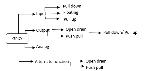
- Pin Mode : Each port bit of the general-purpose I/O (GPIO) ports can be individually configured by software in several modes:
- input or output
- analog
- alternate function (AF).
- Pin characteristics :
- Input : no pull-up and no pull-down or pull-up or pull-down
- Output : push-pull or open-drain with pull-up or pull-down capability
- Alternate function : push-pull or open-drain with pull-up or pull-down capability.
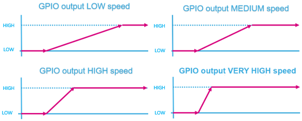
1.1. GPIO (pin) output-speed configuration
- Change the rising and falling edge when the pin state changes from high to low or low to high.
- A higher GPIO speed increases the EMI noise from STM32 and increases the STM32 consumption.
- It is good to adapt the GPIO speed to the peripheral speed. For example, low speed is optimal for toggling GPIO at 1 Hz, while using SPI at 45 MHz requires very high speed setting.
2. Configure GPIO for LED toggling
2.1. Objective
Learn how to Toggle a pin on STM32L476 Nucleo board using Hardware Abstraction Layer (HAL) library and learn how to setup the pin and GPIO port in STM32CubeIDE.
2.2. Create the project in STM32CubeIDE
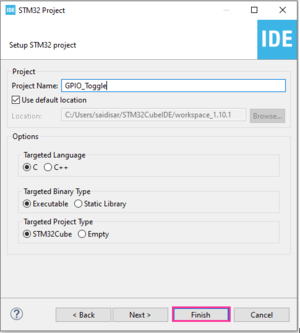
- File > New > STM32 Project in main panel.
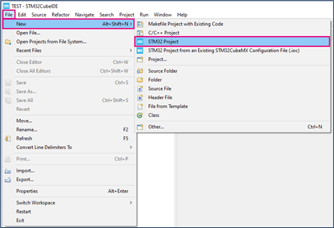
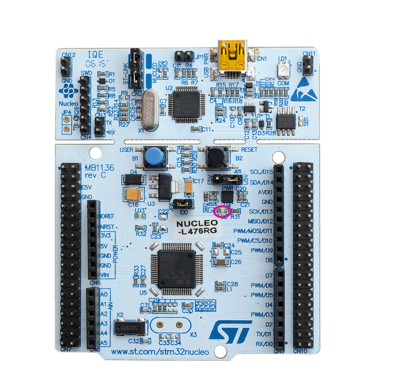
This example uses the NUCLEO-L476RG board.
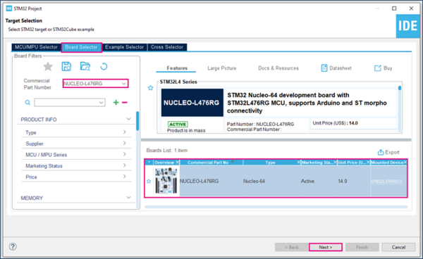
- Select NUCLEO-L476RG using the Board Selector as shown in the figure below:
In case you haven't downloaded the STM32L476 Cube library, it will be downloaded automatically. This however may take some time.
- You will then get a popup asking if you want to initialize peripherals to their default configuration.
- No need to configure any peripheral as only the core/Flash/SRAMs are used (default peripherals).
.
2.3. Configure GPIO
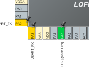
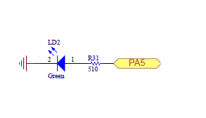
- If you want to start the project with a board, the LED pin is already selected (PA5 on NucleoL476RG. For other boards refer to the user manual).
- Yellow pins are related to the power supply
- Unused pins are marked as Grey
- Yellow pins are related to the power supply
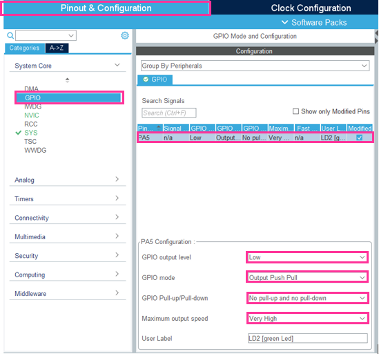
- Select the push-pull mode
- No pull-up and pull-down
- Output speed set to very high is important for faster peripherals such as SPI or USART.
2.4. Generate project and edit main.c
The easiest way to generate the code is to save your current project : Ctrl + S
The code is generated so you can see it in the left side of the screen in the project explorer
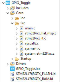
Now, open the main.c file which is the main source file for this application
- The LED toggling is done with a HAL function inside main.c
 /* USER CODE BEGIN 3 */
  /* Infinite loop */
  {
    HAL_GPIO_TogglePin(LD2_GPIO_Port,LD2_Pin);
    HAL_Delay(500);
  }
  /* USER CODE END 3 */
2.5. Compile and flash
Every 500 ms the green LED state changes.
