This article explains what is UART and how to use it through examples
1. What is a Universal Asynchronous Receiver Transmitter (UART)?
The universal synchronous/asynchronous receiver transmitter (USART/UART) offers a flexible means of full-duplex data exchange with external equipment requiring an industry standard NRZ asynchronous serial data format. USART can operate with a very wide range of baud rates using a programmable baud rate generator.
It supports synchronous one-way communication and half-duplex single-wire communication, as well as multiprocessor communications. It also supports the LIN (Local Interconnect Network), Smartcard protocol and IrDA (Infrared Data Association) SIR ENDEC specifications and Modem operations (CTS/RTS).
High speed data communication is possible by using the DMA (direct memory access) for multibuffer configuration. Also, the UART can be used with interrupt.
This article goes through the following UART features:
- Simple UART communication in polling mode
- UART with Interrupt
- UART with DMA
2. Objectives
Learn how to set up UART and generate code with STM32CubeIDE and how to use HAL functions.
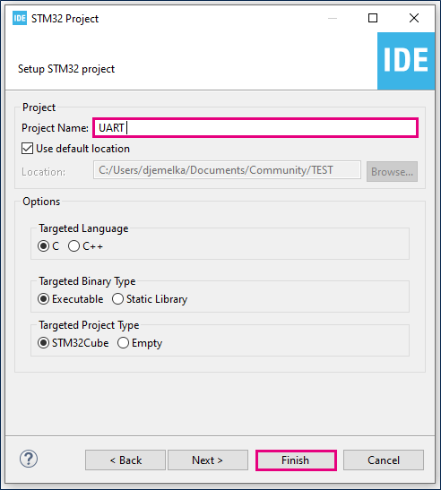
3. Create the project in STM32CubeIDE
- File > New > STM32 Project in main panel.
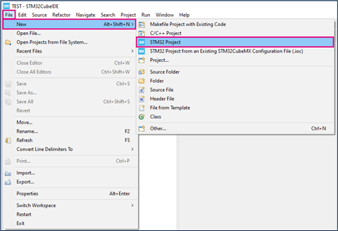
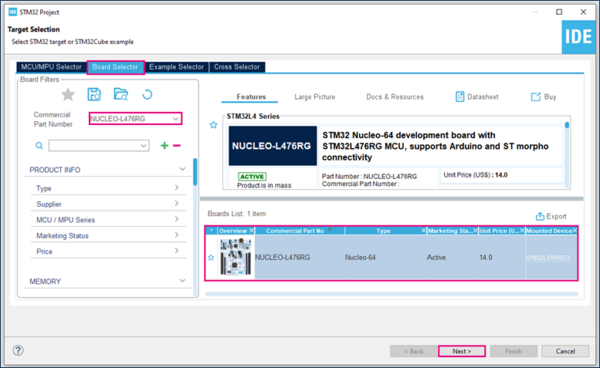
This example uses the NUCLEO-L476RG board.
- Select NUCLEO-L476RG board using Board Selector as shown in the figure below:
In case you haven't downloaded the STM32L476 Cube library, it will be downloaded automatically. This however may take some time.
- Save the project.
- Initialize all peripherals with their default settings.
Answer “Yes” to initialize all peripherals with their default mode? Popup as below:

4. UART Configuration
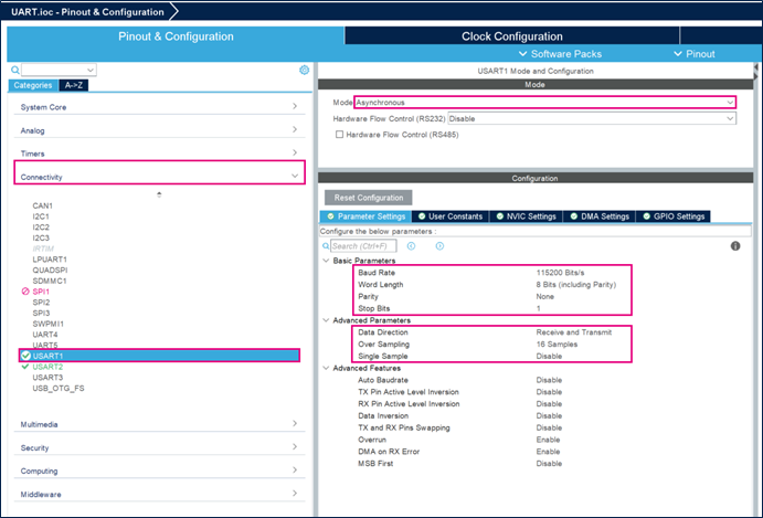
- Set USART1 mode to Asynchronous mode
- Configure Parameter Settings as shown in the figure below:
5. GPIO Configuration
To select the correct GPIOs pins, it is necessary to refer to the datasheet. Look for the alternate function table.
STM32L476 USART1 uses PA9 for transmission (TX) and PA10 for reception (RX) as shown below:
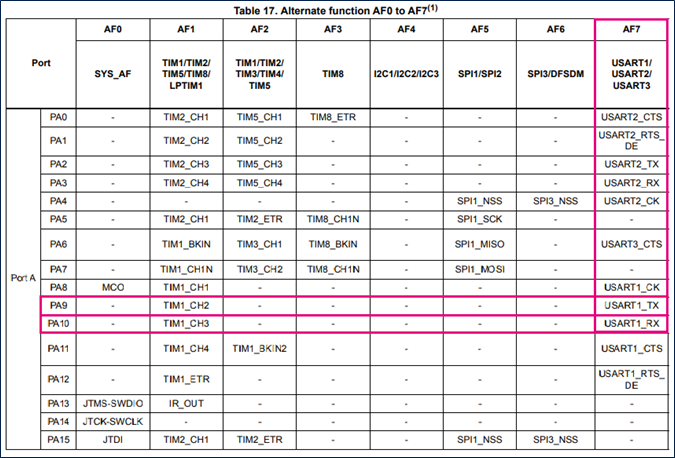
PA9 and PA10 should be configured as follows:

6. Generate source code
Click "Ctrl+S" to generate the project
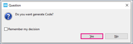
6.1. Simple UART Communication in polling mode
6.1.1. Hardware preparation
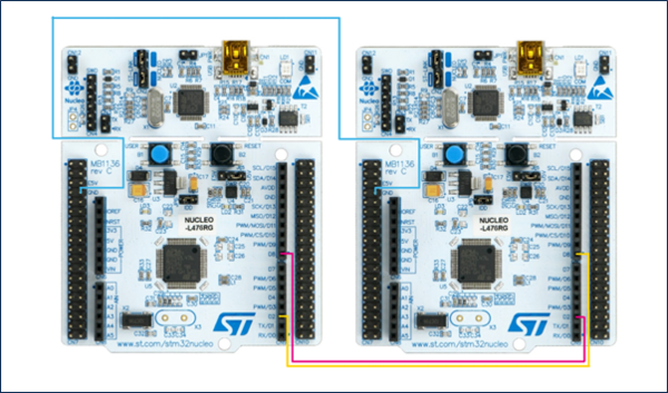
You will need a pair of boards, one will act as transmitter and the other as receiver.
The two boards should be connected as follows:
- Board 1 RX connected to board 2 TX
- Board 1 TX connected to board 2 RX
- Board 1 GND connected to board 2 GND
6.1.2. Edit main.c (TX)
- Create a TX buffer
/* USER CODE BEGIN 0 */
uint8_t tx_buff[]={0,1,2,3,4,5,6,7,8,9};
/* USER CODE END 0 */
- Transmit data
/* Infinite loop */
/* USER CODE BEGIN WHILE */
while (1)
{
  /* USER CODE END WHILE */

  /* USER CODE BEGIN 3 */

  HAL_UART_Transmit(&huart1, tx_buff, 10, 1000);
  HAL_Delay(10000);

}
/* USER CODE END 3 */
- Compile and flash (TX)
First of all, build your project ![]()
Connect the first NUCLEO-L476RG board. It will act as the TX board in this example.
Then, run your program ![]()
The debug configurations window will open. Rename your configuration as UART Debug TX.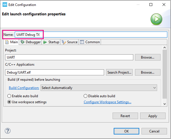
In the debugger tab, click ST-LINK S/N and scan. A number will appear: this is your TX board ST-LINK serial number used to indicate that this debug configuration is related to this specific board.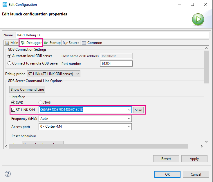
Click OK and the program will run autonomously on the TX board.
Now, connect the second NUCLEO-L476RG board. It will act as the RX board in this example. Let's go through the code for this board.
6.1.3. Edit main.c (RX)
- Create a RX buffer
/* USER CODE BEGIN 0 */
uint8_t rx_buff[10];
/* USER CODE END 0 */
- Receive data
/* Infinite loop */
/* USER CODE BEGIN WHILE */
while (1)
{
  /* USER CODE END WHILE */

  /* USER CODE BEGIN 3 */
  if(HAL_UART_Receive(&huart1, rx_buff, 10, 1000)==HAL_OK) //if transfer is successful
  {
    __NOP(); //You need to toggle a breakpoint on this line!
  } else {
    __NOP();
  }
}
/* USER CODE END 3 */
We will use this breakpoint to stop the program after data is received, and check rx_buff[] value.
- Compile and flash (RX)
First, we need to create a new debug configuration for the RX board.
Click the little arrow of the debug button ![]() and click Debug Configurations...
Then click the New launch configuration button.
and click Debug Configurations...
Then click the New launch configuration button.
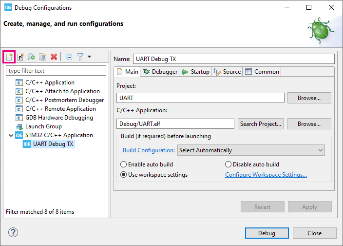
Rename this configuration as UART Debug RX.
Just as we did for the previous configuration, in the debugger tab, click ST-LINK S/N and scan. Make sure to select the new serial number that appears: it belongs to the RX board we just connected.
Then click Debug.
Click the Resume button ![]() to execute the code.
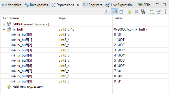
Code execution should stop at the breakpoint we toggled earlier. Now hover over rx_buff[] to monitor its value.
to execute the code.
Code execution should stop at the breakpoint we toggled earlier. Now hover over rx_buff[] to monitor its value.
Alternatively, you can add rx_buff to Expressions, on the right side of STM32CubeIDE.
6.2. UART with Interrupt
6.2.1. Hardware preparation
Remain in the same configuration as previously.
Both TX and RX boards should be connected to your computer.
6.2.2. Configure UART Interrupt
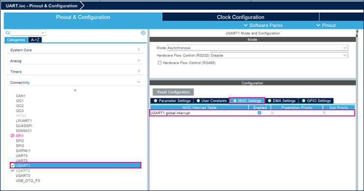
Open the UART.ioc file in the STM32CubeIDE project as shown in the figure below:
Enable USART1 global interrupt.
6.2.3. Generate project and edit main.c
Click "Ctrl+S" to generate the project
- Create a TX buffer
/* USER CODE BEGIN 0 */
uint8_t tx_buff[]={65,66,67,68,69,70,71,72,73,74}; //ABCDEFGHIJ in ASCII code
/* USER CODE END 0 */
- Transmit data
/* Infinite loop */
/* USER CODE BEGIN WHILE */
while (1)
{
  /* USER CODE END WHILE */

  /* USER CODE BEGIN 3 */

  HAL_UART_Transmit_IT(&huart1, tx_buff, 10);
  HAL_Delay(10000);

}
/* USER CODE END 3 */
- Compile and flash
The program will run autonomously on the TX board.
Now, let's go through RX board code. Don't forget to clear the previous code.
- Create a RX buffer
/* USER CODE BEGIN 0 */
uint8_t rx_buff[10];
/* USER CODE END 0 */
- Start reception
/* USER CODE BEGIN 2 */
HAL_UART_Receive_IT(&huart1, rx_buff, 10);
/* USER CODE END 2 */
- Reception completed callback
/* USER CODE BEGIN 4 */
void HAL_UART_RxCpltCallback(UART_HandleTypeDef *huart)
{
  HAL_UART_Receive_IT(&huart1, rx_buff, 10); //You need to toggle a breakpoint on this line!
}
/* USER CODE END 4 */
We will use this breakpoint to stop the program after data is received, and check rx_buff[] value.
In this callback, you can use HAL_UART_Receive_IT to keep receiving data, otherwise you will only receive it once.
Debug your RX project ![]()
Click the Resume button ![]() to execute the code.
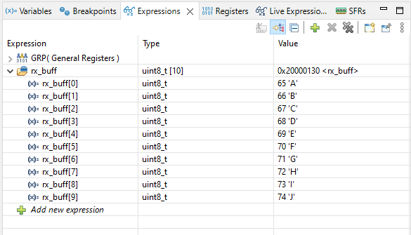
Code execution should stop at the breakpoint we toggled earlier. Add rx_buff to Expressions, on the right side of STM32CubeIDE, to monitor its value.
to execute the code.
Code execution should stop at the breakpoint we toggled earlier. Add rx_buff to Expressions, on the right side of STM32CubeIDE, to monitor its value.
6.3. UART with DMA
6.3.1. Hardware preparation
Remain in the same configuration as previously.
Both TX and RX boards should be connected to your computer.
6.3.2. Configure UART DMA
Open the UART.ioc file in the STM32CubeIDE project as shown in the figure below:
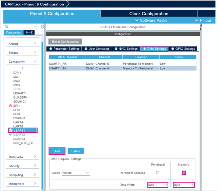
Add the DMA request as shown in the figure below:
6.3.3. Generate project and edit main.c
Click "Ctrl+S" to generate the project
- Create a TX buffer
/* USER CODE BEGIN 0 */
uint8_t tx_buff[]={65,66,67,68,69,70,71,72,73,74}; //ABCDEFGHIJ in ASCII code
/* USER CODE END 0 */
- Transmit data
/* Infinite loop */
/* USER CODE BEGIN WHILE */
while (1)
{
  /* USER CODE END WHILE */

  /* USER CODE BEGIN 3 */

  HAL_UART_Transmit_DMA(&huart1, tx_buff, 10);
  HAL_Delay(10000);

}
/* USER CODE END 3 */
- Compile and flash
The program will run autonomously on the TX board.
Now, let's go through RX board code. Don't forget to clear the previous code.
- Create a RX buffer
/* USER CODE BEGIN 0 */
uint8_t rx_buff[10];
/* USER CODE END 0 */
- Start reception
/* USER CODE BEGIN 2 */
HAL_UART_Receive_DMA(&huart1, rx_buff, 10);
/* USER CODE END 2 */
- Reception completed callback
/* USER CODE BEGIN 4 */
void HAL_UART_RxCpltCallback(UART_HandleTypeDef *huart)
{
  HAL_UART_Receive_DMA(&huart1, rx_buff, 10); //You need to toggle a breakpoint on this line!
}
/* USER CODE END 4 */
We will use this breakpoint to stop the program after data is received, and check rx_buff[] value.
In this callback, you can use HAL_UART_Receive_DMA to keep receiving data, otherwise you will only receive it once.
Debug your RX project ![]()
Click the Resume button ![]() to execute the code.
Code execution should stop at the breakpoint we toggled earlier. Add rx_buff to Expressions, on the right side of STM32CubeIDE, to monitor its value.
to execute the code.
Code execution should stop at the breakpoint we toggled earlier. Add rx_buff to Expressions, on the right side of STM32CubeIDE, to monitor its value.

