This article explains what DMA is and how to use it through examples.
1. What is DMA?
DMA stands for Direct Memory Access controller.
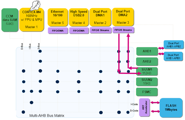
DMA is a bus master and system peripheral providing high-speed data transfers between peripherals and memory, as well as memory-to-memory.
Data can be quickly moved by DMA without any CPU action, keeping CPU resources free for other operations.
This article uses the STM32L476 device as an example. The STM32L476 device embeds 2 DMAs: DMA1 and DMA2.
Each channel is dedicated to managing memory access requests from one or more peripherals. The two DMA controllers have 14 channels in total. Each channel has an arbiter to handle priority between DMA requests.
| DMA features | DMA1 | DMA2 |
| Number of regular channels | 7 | 7 |
1.1. Objectives
- Learning how to setup DMA transfer in STM32CubeIDE.
- Creating simple DMA memory-to-memory transfer from RAM to RAM and transfer with interrupt.
1.2. DMA memory-to-memory example overview
- Using STM32CubeIDE and generating code with DMA.
- Learning how to setup DMA using HAL.
- Verifying the correct functionality by comparing transferred buffers.
2. Creating the project in STM32CubeIDE
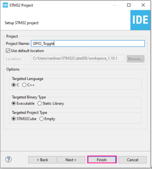
The example below uses the NUCLEO-L476RG board[1] .
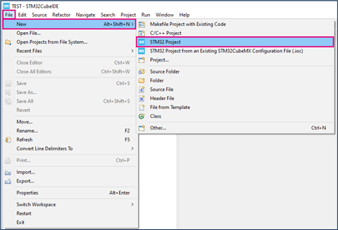
- File > New > STM32 Project in main panel.
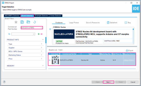
- Select the NUCLEO-L476RG board using the Board Selector, as shown in the figure below:
- If not downloaded previously, the download of the STM32CubeL4 Cube library starts automatically. The download may take some time.
- Save the project.
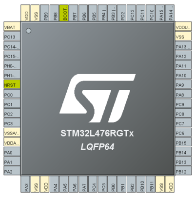
- Pin configuration is not required for DMA.
3. Memory-to-memory mode
DMA channels may operate without being triggered by a request from a peripheral. This mode is called memory-to-memory mode, and is initiated by software.
It allows transfer from one address location to another without a hardware request. Once the channel is configured and enabled, the transfer starts immediately.
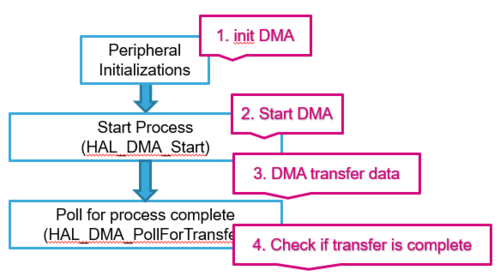
3.1. DMA process workflow summary
- At the beginning of the main program, HAL_DMA_Init() is called to reset all peripherals, initialize flash interface and systick.
- HAL_DMA_Start() starts the DMA transfer after the configuration of source and destination addresses, as well as the length of data to be transferred.
- HAL_DMA_PollForTransfer() polls for the end of current transfer. In this case a fixed timeout can be configured by user depending on his application.
Once the transfer is completed, it is recommended to handle the return values to make sure the program worked as expected.
- HAL_OK: DMA transfer was successfully finished and data was transferred to destination without error.
- HAL_ERROR: Error occured during DMA transfer. You can use HAL_DMA_GetError for details.
- HAL_BUSY: DMA transfer in progress, user can only abort the transfer
3.2. DMA M2M Configuration
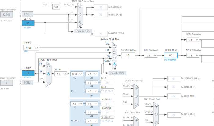
In STM32CubeMX, click Clock Configuration. Your clock settings should look like this:
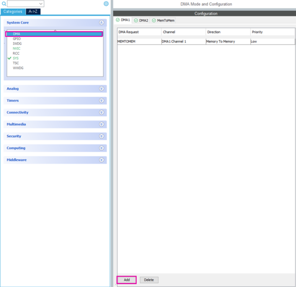
Now, click Pinout & Configuration > DMA > DMA1 Button Add.
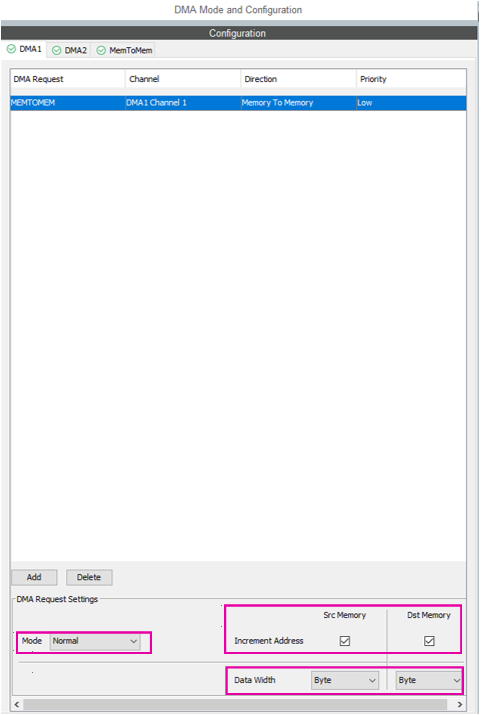
Configure DMA as follows:
- MEMTOMEM DMA request : DMA1 Channel 1
- Normal mode
- Increment source and destination addresses
- Byte data width
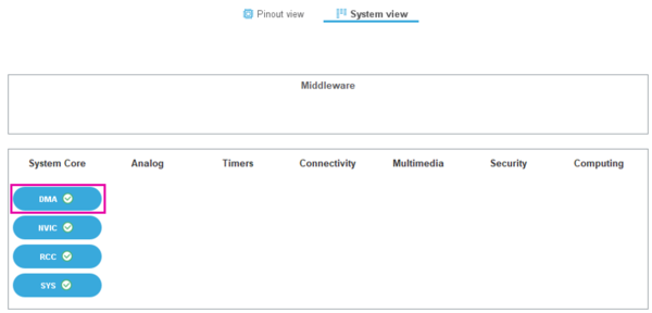
- Check system DMA in System view :
- Generate the code by pressing Ctrl + S:
- Open main.c using the Project Explorer: myproject / Src / main.c.
- Create two buffers: the firtst for source data, and the second as destination buffer.
/* USER CODE BEGIN 0 */
uint8_t Buffer_Src[]={0,1,2,3,4,5,6,7,8,9};
uint8_t Buffer_Dest[10];
/* USER CODE END 0 */
/* USER CODE BEGIN 2 */
HAL_DMA_Start(&hdma_memtomem_dma1_channel1, (uint32_t) (Buffer_Src), (uint32_t) (Buffer_Dest), 10);
while(HAL_DMA_PollForTransfer(&hdma_memtomem_dma1_channel1, HAL_DMA_FULL_TRANSFER, 100) != HAL_OK)
{
  __NOP();
}
/* USER CODE END 2 */
3.3. Compile and flash
- Click Debug button to run step by step

- Click Resume to continue execution

- Click Suspend to stop execution

Add Buffer_Src and Buffer_Dest to Expressions, on the right side of STM32CubeIDE, to monitor their value. Source data has been transferred to destination buffer.
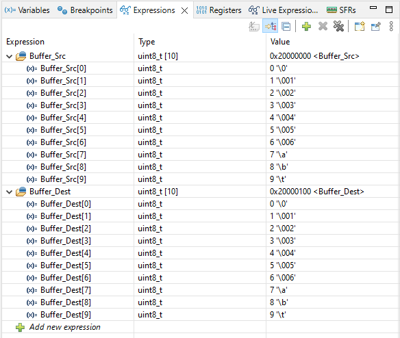
This method requires polling for transfer status. The method to achieve memory-to-memory transfer with interrupts is described below.
4. Memory-to-memory transfer with Interrupt
- To configure DMA with Interrupt, follow the steps detailed in the Memory-to-memory mode section.
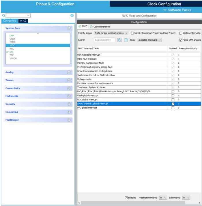
- Enable DMA1 Channel 1 Global Interrupt In System Core > NVIC as shown in the figure below:
- Now generate the code by pressing : Ctrl + S
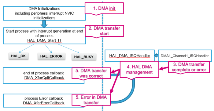
4.1. HAL Library DMA with IT flow
- DMA intialization is generated in main.c.
- HAL_DMA_Start_IT: Start DMA buffer transfer
- DMA1_Channel1_IRQHandler is generated in stm32f4xx_it.c: it indicates whether the DMA process is half/complete or an error was detected.
- HAL_DMA_IRQHandler is defined in stm32f4xx_hal_dma.c: Process interrupt information.
- DMA_XferCpltCallback: Data correctly transferred complete callback function.
- DMA_XferErrorCallback: Error was detected Error callback function.
4.2. DMA M2M with IT Configuration
We will be using the same code as in DMA M2M Configuration.
/* USER CODE BEGIN 0 */
void XferCpltCallback(DMA_HandleTypeDef *hdma);
uint8_t Buffer_Src[]={0,1,2,3,4,5,6,7,8,9};
uint8_t Buffer_Dest[10];
/* USER CODE BEGIN 0 */
/* USER CODE BEGIN 4 */
void XferCpltCallback(DMA_HandleTypeDef *hdma)
{
  __NOP(); //Line reached only if transfer was successful. Toggle a breakpoint here
}
/* USER CODE END 4 */
Before we start the DMA with interrupt, we need to set the callback into DMA structure.
Then, it is possible to use the HAL_DMA_Start_IT to begin DMA transfer.
/* USER CODE BEGIN 2 */
hdma_memtomem_dma1_Channel1.XferCpltCallback=&XferCpltCallback;
HAL_DMA_Start_IT(&hdma_memtomem_dma1_Channel1,(uint32_t)Buffer_Src,(uint32_t)Buffer_Dest,10);
/* USER CODE END 2 */
4.3. Compile and flash
If you toggled a breakpoint in your callback function, execution should stop automatically.
Add Buffer_Src and Buffer_Dest to Expressions, on the right side of STM32CubeIDE, to monitor their value. Source data has been transferred to destination buffer.

5. References
