This article presents a video on how to use a technique called "Transfer learning" to quickly train a deep learning model in order to classify images.
This video teaches you how to use ST ecosystem to build a computer vision application from the ground up. It describes how the FP-AI-VISION1 allows easy image collection with an STM32 Discovery kit, how to use transfer learning with Tensorflow to quickly train an image classification model, and eventually how to use STM32Cube.AI to convert this model into optimized code for ST microcontrollers.
The Jupyter notebook used in this video is available on Github. It can be opened with Colab.
The article below describes step by step the video tutorial. For another complete example on how to use your own models with the FP-AI-VISION1 and Teachable Machine check out this article. In addition, this series of videos gives a good overview of the Vision function package.
1. Dataset generation
First you need a dataset of images representative of your classes. It can be generated either by following the steps described below or by using an already existing dataset (see related Github page for pasta datasets to jump start, note that it has been recorded with a fix distance of 13 cm and good light conditions). It is a good idea to use the same sensor for the dataset collection as the one that will be used for inference.
In the present example, the B-CAMS-OMV board is used as camera module.
Download the FP-AI-VISION1 function package from https://www.st.com/en/embedded-software/fp-ai-vision1.html.
Using the USB Webcam application provided within FP-AI-VISION1, the board and the camera can be used as a webcam.
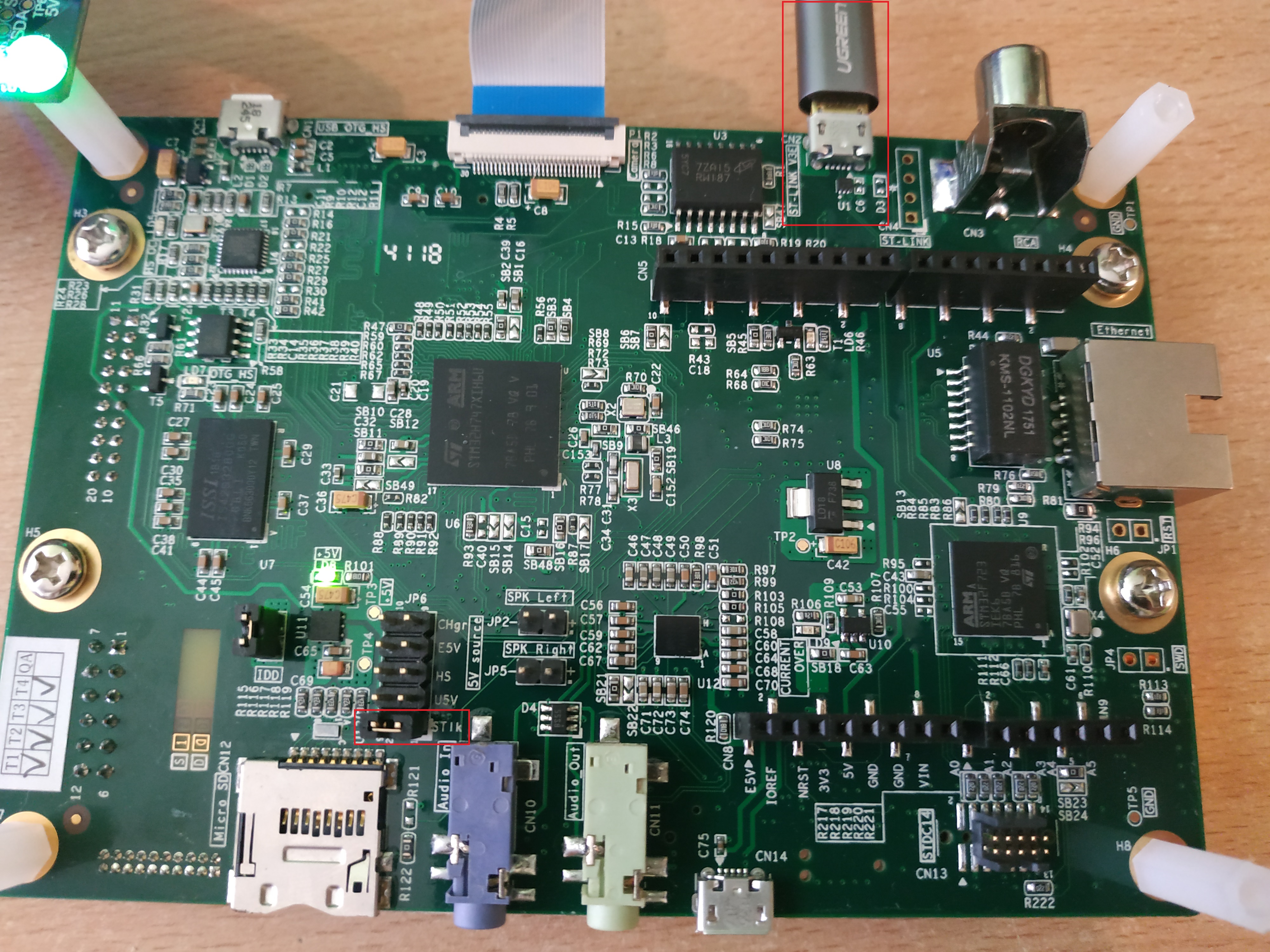
First plug your board onto your computer using the ST-LINK port. Make sure the JP6 jumper is set to ST-LINK.
After plugging the USB cable onto your computer, the board appears as a mounted device.
The binary is located under FP-AI-VISION1_V3.1.0\Projects\STM32H747I-DISCO\Applications\USB_Webcam\Binary.
Drag and drop it onto the board mounted device. This flashes the binary on the board.
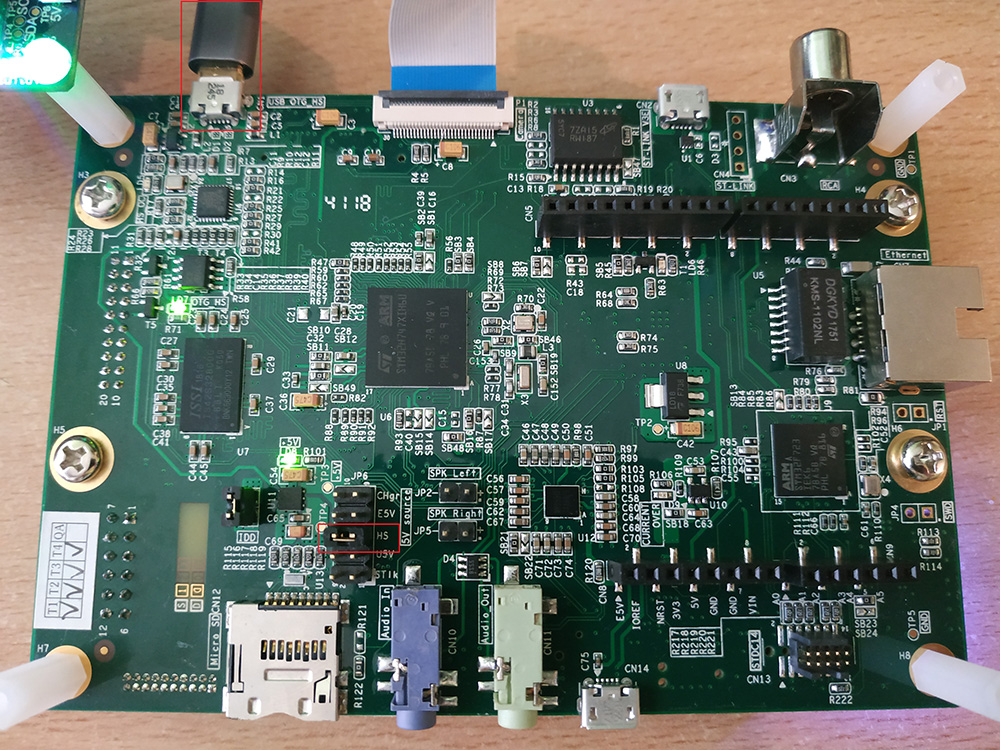
Unplug the board, change the JP6 jumper to the HS position, and plug your board using the USB OTG port.
For convenience, you can plug simply two USB cables, one on the USB OTG port, the other on the USB ST-LINK and set the JP6 jumper to ST-LINK. In this case, the board can be programmed and switch from USB webcam mode to test mode without the need to change the jumper position.
Launch the Windows® camera application (it can be found by searching for “camera” in the Windows search bar). If your computer has already a camera, change the source of the image feed by clicking the “flip camera” button.
The capture can be done either in VGA or QVGA, the resolution can be changed with the menu settings -> Photos -> Quality.
The images will be resized to the input resolution of the neural network in the Python notebook.
Take enough picture samples to fill your dataset. It must be structured as follows:
Dataset
    ├── cats
    │   ├── cat0001.jpg
    │   ├── cat0002.jpg
    │   └── ...
    ├── dogs
    └── horses
The dataset must to be large enough. The one used for the video includes 1408 files belonging to 8 classes. It is recommended to use at least 100 pictures per class.
2. Model generation
The Python notebook used to generate the model can be found at https://github.com/STMicroelectronics/stm32ai/blob/master/AI_resources/VISION/transfer_learning/TransferLearning.ipynb
It can be open either with Google Colab (as in the present example) or by using any Python environment.
Just click (or Ctrl + Click) the Open in Colab icon at the top of the notebook on Github. This takes you to the Colab notebook project.
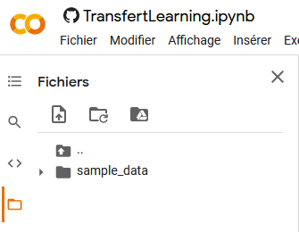
Zip your dataset folder and import it to the Colab project.
You can run the script either step by step or run the whole script by pressing Ctrl + F9.
All the steps are described in details in the script but what they do is straightforward :
- Import all the necessary libraries.
- Unzip the dataset.
- Import the dataset (this step also automatically resizes images to match the model input size).
- Display samples from the dataset
- Perform data augmentation by adding duplicate images with random contrast/translation/rotation/zoom.
- Display new samples.
- Normalize data.
- Import a pretrained
MobileNetmodel without the last layer and add new ones at the end. - Train the model.
- Plot training loss history.
- Quantize the model to reduce its size.
- Export the quantized model.
The trained and quantized model appears as model_quant.tflite.
3. Model deployment
This section describes how to generate a model that can be used on STM32 platforms, starting from a model produced by a high-level library such a Keras/Tensorlflow.
It also describes how to use your model in an already existing project.
3.1. Model generation for STM32
First convert the tflite model to be used on a STM32 platform.
There are two ways to achieve this goal, one by using STM32CubeMX and generating an entire project (recommended at first), the other by using the command line interface to generate only the required files.
3.1.1. Project generation with STM32CubeMX (Option 1)
Start STM32CubeMX and create a new project. In this example, the STM32H747I-DISCO board is used. Select the board in the Board Selector and start the project.
A new window opens showing the board configuration. Click Software Packs -> Select Components.
Select the components for the Arm® Cortex®-M7 core under STMicroelectronics X-CUBE-AI, check the core box, select Application as application, then click Ok.
The stm32-ai library will be download if it has not been downloaded yet. When it is complete, click Ok.
Go to Software Packs (on the left) -> STMicroelectronics X-CUBE-AI. A pop up window opens to configure peripherals and clock.Click Yes.
Click Add network, call your network network, select TFLite from the scrollable menu, and browse to the last section to find the generated model.
Once the model is selected, click Analyze. This provides a quick overview of the model memory footprint. Click the Show graph button for more in-depth information on the model topology and RAM memory usage layer by layer including activation buffers.
Click the gear icon (Advanced Settings). Make sure that the options Use activation buffer for input buffer is selected and unselect the option Use activation buffer for output buffer. This option allows to reduce the memory usage by reusing the input buffer for the activations. Do not change any other settings to be aligned with the function pack configuration.
Click Analyze again. You can see that the RAM occupation has been significantly reduced (refer to the memory graph for more details).
Check that the model works properly by validating it either on the PC or on the target.
To generate the code for STM32CubeIDE (or Arm® KEIL® or IAR SYSTEMS®) go to Project manager, specify a project name and location. Select STM32CubeIDE as toolchain, then click GENERATE CODE on the top right corner.
This generates the necessary code for the whole project. In the present example, only the files related to the neural network are required.
They are located under YourProjectName\CM7\X-CUBE-AI\App\ and are called network.c,network.h ,network_data.c, network_data.h and network_config.h.
If you are using X-CUBE-AI v7.2.0 (or above) two additional files are generated network_data_params.c and network_data_params.h. They represent the model and its weight.
3.1.2. Command line interface (Option 2)
The other way to generate the necessary files is to use the command line interface. The main advantage is to produce only the required files.
The documentation related to X CUBE AI (example with X-CUBE_AI v7.1.0) is located under C:\Users\<USERNAME>\STM32Cube\Repository\Packs\STMicroelectronics\X-CUBE-AI\7.1.0\Documentation/.
The CLI is called stm32ai.exe for Windows (example with X-CUBE_AI v7.1.0). It is located under C:\Users\<USERNAME>\STM32Cube\Repository\Packs\STMicroelectronics\X-CUBE-AI\7.1.0\Utilities\windows and $HOME/STM32Cube/Repository/Packs/STMicroelectronics/X-CUBE-AI/7.1.0/Utilities/ for UNIX®-based systems.
If there is no utilities folder, create a CUBE MX project and add Core AI in the Software Package (see section Project generation). This downloads all the necessary files.
For ease of usage, add the X-Cube-AI installation folder to your path, for Windows:
- For X-CUBE-AI v7.1.0:
 set CUBE_FW_DIR=C:\Users\<USERNAME>\STM32Cube\Repository
 set X_CUBE_AI_DIR=%CUBE_FW_DIR%\Packs\STMicroelectronics\X-CUBE-AI\7.1.0
 set PATH=%X_CUBE_AI_DIR%\Utilities\windows;%PATH%
- For X-CUBE-AI v7.2.0:
 set CUBE_FW_DIR=C:\Users\<USERNAME>\STM32Cube\Repository
 set X_CUBE_AI_DIR=%CUBE_FW_DIR%\Packs\STMicroelectronics\X-CUBE-AI\7.2.0
 set PATH=%X_CUBE_AI_DIR%\Utilities\windows;%PATH%
Once added, go to the folder where you wish to generate the network files in command line (using PowerShell or similar) and run the following command:
stm32ai.exe generate -m .\model_quant.tflite --allocate-inputs # (change the path to the model if needed).
This creates all the necessary files under the stm32ai_output folder.
3.2. Model integration onto FP-AI-VISION1
In this part we will import the new model into the FP-AI-VISION1 function pack. This function pack provides a software example for Person presence detection application. For more information on FP-AI-VISION1, go here.
Launch the STM32CubeIDE project with the .project located under FP-AI-VISION1_V3.1.0\Projects\STM32H747I-DISCO\Applications\PersonDetection\MobileNetv2_Model\STM32CubeIDE. Double click it to open STM32CubeIDE.
Select the CM7 subproject and build it. The resulting workspace is shown below:
Replace the model files (network.c,network.h ,network_data.c, network_config.h and network_data.h) by those generated previously with STM32CubeMX.
If you are using X-CUBE-AI v7.2.0 (or above) two additional files are generated network_data_params.c and network_data_params.h.
Replace them in Windows explorer. Below the file location:
PersonDetection
+-- MobileNetv2_Model
|   +-- CM7
|   |   +-- Inc
|   |   |   network.h
|   |   |   network_data.h
|   |   |   network_data_params.h (for X-CUBE-AI v7.2 and above)
|   |   |   network_config.h
|   |   +-- Src
|   |   |   network.c
|   |   |   network_data.c
|   |   |   network_data_params.c (for X-CUBE-AI v7.2 and above)
From STM32CubeIDE, open fp_vision_app.c. Go to line 125 where the output_labels is defined and update this variable with your label names. Be careful that there are as many labels as your model output size.
// fp_vision_app.c line 125
const char* output_labels[AI_NET_OUTPUT_SIZE] = {
    "Conchiglie", "Coquillette", "Corti", "Farfalle", "Fusilli", "GreenConchiglie", "Macaroni", "Penne", "RedConchiglie"};
3.2.1. Updating to a newer version of X-CUBE-AI
FP-AI-VISION1 v3.1.0 is based on X-Cube-AI version 7.1.0, If the c-model files were generated with a newer version of X-Cube-AI (> 7.1.0), you need also to update the X-CUBE-AI runtime library (NetworkRuntime720_CM7_GCC.a for X-CUBE-AI version 7.2).
Go to workspace/FP-AI-VISION1_V3.1.0/Middlewares/ST/STM32_AI_Runtime then for a Windows command prompt:
 copy %X_CUBE_AI_DIR%\Middlewares\ST\AI\Inc\*  .\Inc\
 copy %X_CUBE_AI_DIR%\Middlewares\ST\AI\Lib\GCC\ARMCortexM7\NetworkRuntime720_CM7_GCC.a .\lib\NetworkRuntime710_CM7_GCC.a
You also need to add to the project tree the new generated file network_data_params.c. Simply drag and drop the network_data_params.c within the STM32CubeIDE project in the Applications folder and link to file as shown below:
3.3. Build and test your application
Before compiling the project, we need to download the latest drivers to ensure the best performances using the board hardware.
Go on the GitHub STM32H747I-DISCO BSP website, and download as zip. Unzip the files and copy them in the project folder workspace/FP-AI-VISION1_V3.1.0/Drivers/BSP/STM32H747I-Discovery by replacing the old files.
Download the OTM8009A LCD drivers on GitHub and place the unzipped files inside the folder workspace/FP-AI-VISION1_V3.1.0/Drivers/BSP/Components/otm8009a by replacing the old files.
Download the NT35510 LCD drivers on GitHub, create the folder workspace/FP-AI-VISION1_V3.1.0/Drivers/BSP/Components/nt35510 and place the unzipped files inside.
Now we need to add these files to the CubeIDE project. From your file explorer, drag and drop the nt35510.c and nt35510_reg.c files in STM32CubeIDE in the folder workspace/FP-AI-VISION1_V3.1.0/Drivers/BSP/Components.
Then add the workspace/FP-AI-VISION1_V3.1.0/Drivers/BSP/Components/nt35510 folder to the include paths, click Project->Properties and follow the instructions below:
Clean your project under STM32CubeIDE with Project->Clean....
Make sure that your board is connected to the ST-LINK port and properly powered (set the jumper position to ST-LINK).
Build your project and run it with the play button.
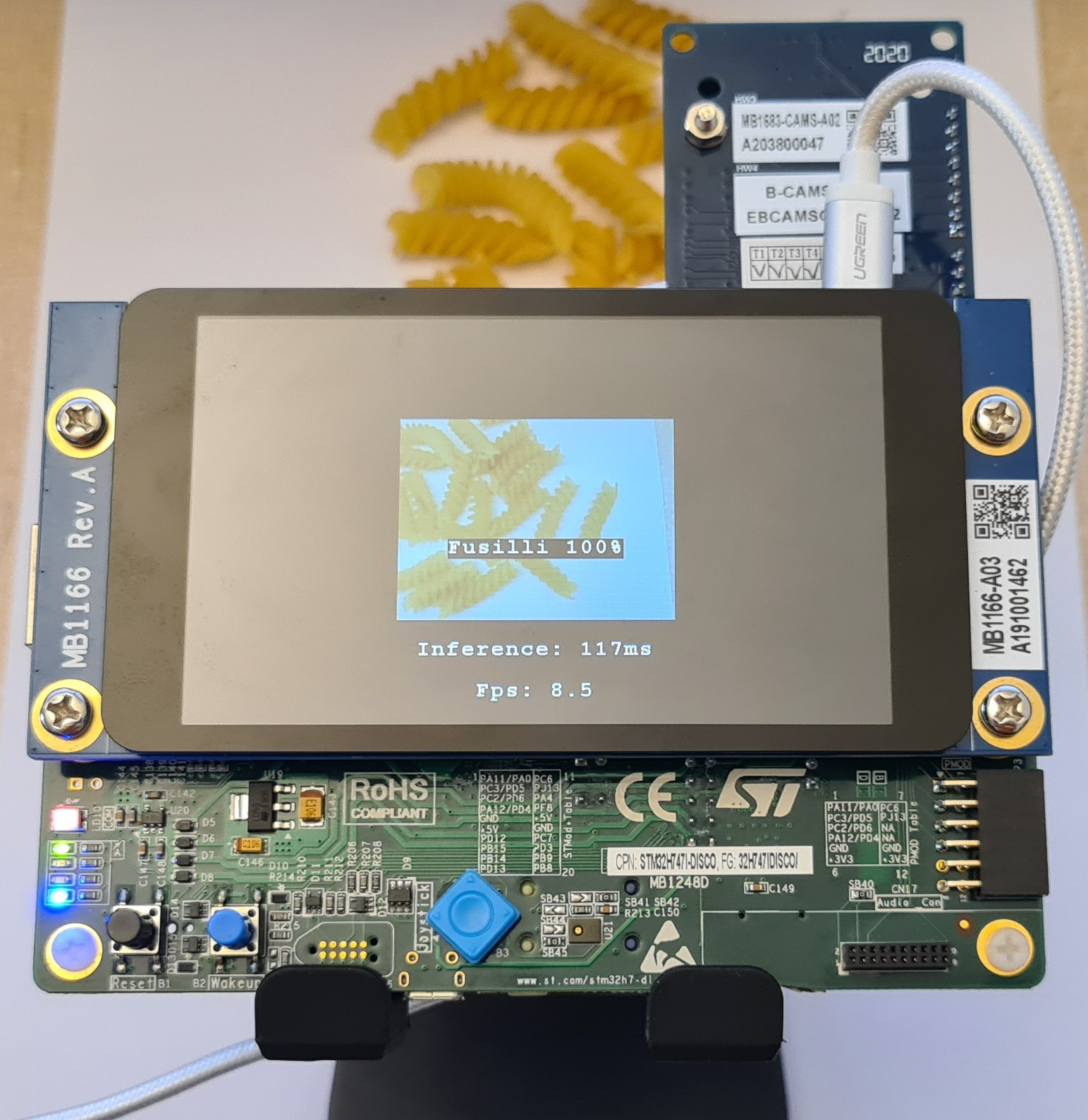
A ST-Application pack splash window appears followed by the camera view and the model classification. If either of these window is not displayed properly, go through the wiki article to check if steps have been skipped.
4. STMicroelectronics references
See also:


