Target description
This tutorial aims to help you to:
- Use the X-NUCLEO-SRC1M1 shield that includes a TCPP02-M18 protection circuit and provides a USB Type-C® connector.
- Create a USB legacy 3 A at 5 V Type-C source application with the NUCLEO-F446RE board that does not include any UCPD peripheral and the X-NUCLEO-SRC1M1 shield by using STM32CubeIDE software.
Prerequisites
- Computer with Windows 7 (or higher)
- Computer with Windows 7 (or higher)
Hardware
- NUCLEO-F446RE (tested on rev C-04)[1]
- X-NUCLEO-SRC1M1 shield[2]
- USB PD Sink device (to test our USB source device, it can be the sink created in this wiki article, or a USB Type-C® mobile phone or device.)
- USB cable Type-A to Mini-B
- USB Type-C® to Type-C® cable
Software
Literature
Create a USB PD source device
![]() Total 50min
Total 50min
1. Software pack installation
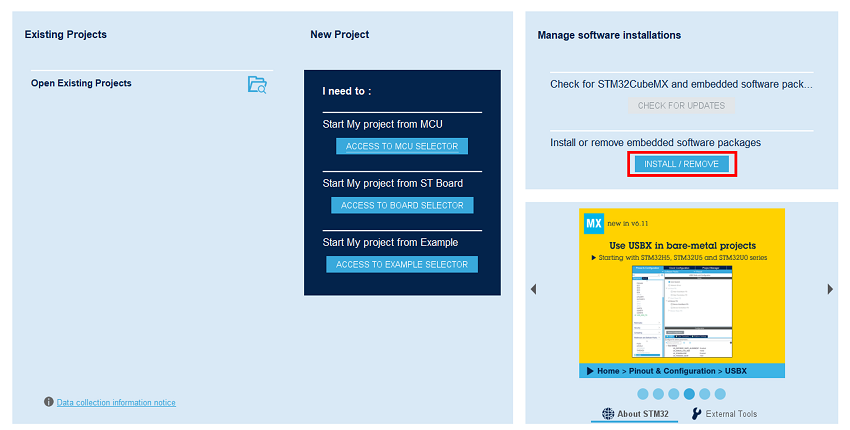
Open STM32CubeMX, in the software pack area, click on the install/remove button.
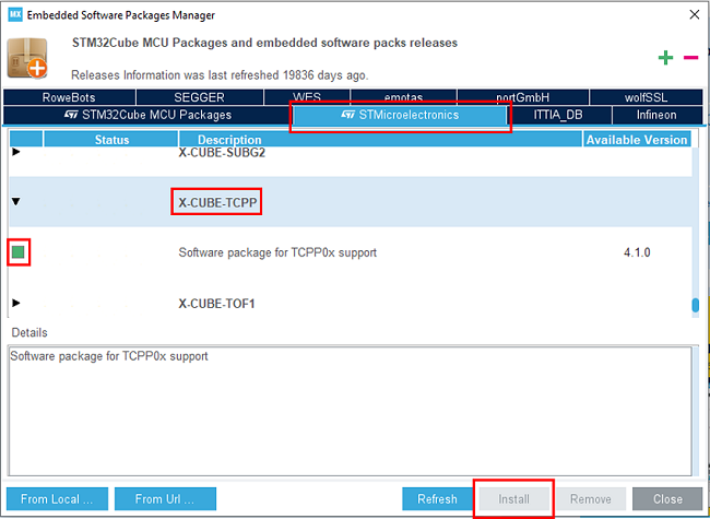
Then select the STMicroelectronics tab, scroll down to the X-CUBE-TCPP software pack, and click on the install button if it is not already installed.
2. Creating the project
![]() 5min
5min
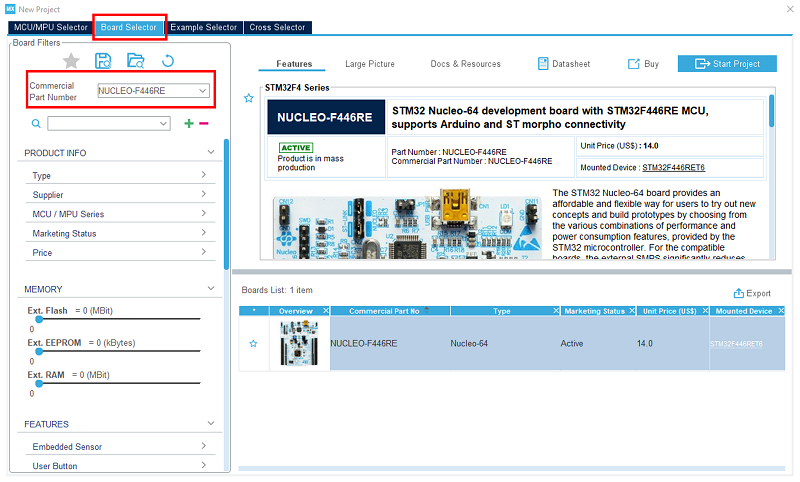
Open STM32CubeIDE and create a new STM32 project. As a target selection, choose the NUCLEO-F446RE from the board selector tab.
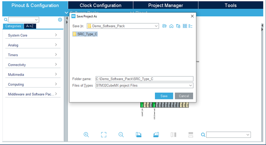
Click on start project, then in the file menu, create a new folder at your project's name, and click on save.
When prompted for initializing peripherals with their default mode, click no.
3. Configuring the system
At this point, your project is created and in the next steps, we will configure the peripherals and options needed for the project.
3.1. Clear the pinout
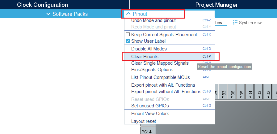
To start from a blank configuration, click on the pinout menu and select clear pinouts. This resets the pinouts in the pinout view.
3.2. Select the X-CUBE-TCPP software pack
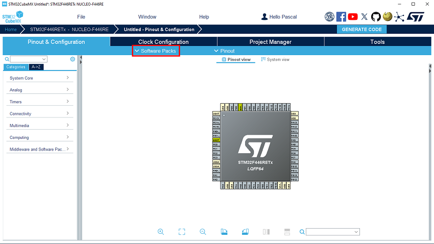
Click on the software packs menu.
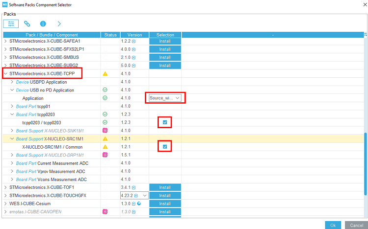
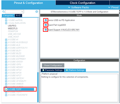
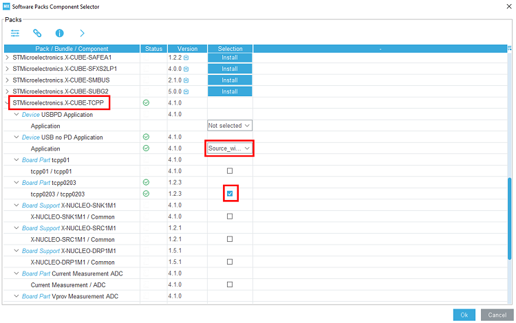
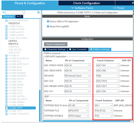
Select the X-CUBE-TCPP software pack and enable its source without UCPD application, the tcpp0203 Board part, and the X-NUCLEO-SRC1M1 Board support.
3.3. Configure the system timebase
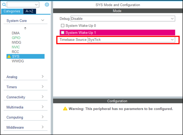
For this simple example, we use SysTick as the system timebase. In the system core section, select SYS and change the timebase source to SysTick.
3.4. Configure ADC peripheral
For this application, VBUS, CC1, and CC2 need to be monitored. To do it, an ADC needs to be configured to measure the VBUS voltage and current, CC1, CC2, and Vprovider.
As we are going to use the X-NUCLEO-SRC1M1 BSP, the ADC configuration does not need to be done in CubeMX.
As we need the ADC HAL drivers for it to work properly, we still need to configure the ADC in CubeMX for it to include the driver files, but the actual configuration and init function will not be called in our project.
In the analog section, enable ADC1 peripheral channel 0. Leave the configuration as default, as the software pack reconfigures it.
3.5. Configure I2C peripheral
As the X-NUCLEO-SRC1M1 shield includes a TCPP02-M18 that communicates via I2C, we need to enable the I2C peripheral in our project.
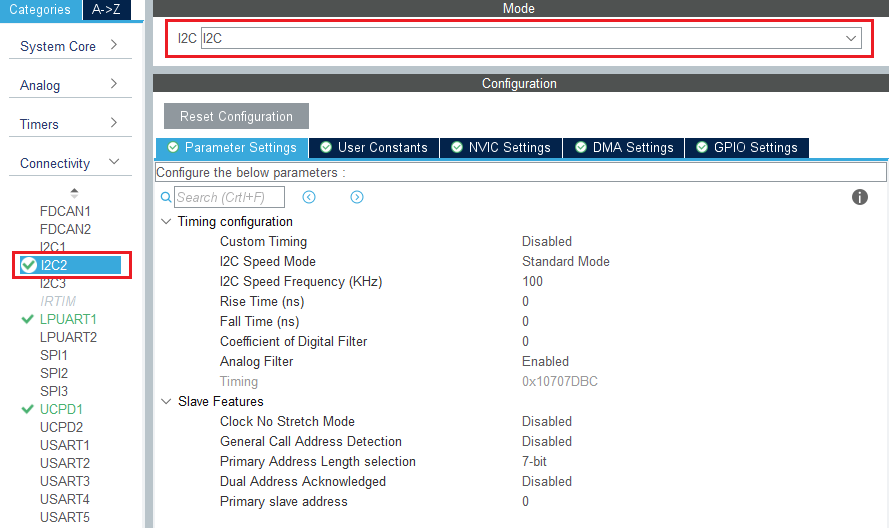
In the connectivity section, enable I2C2 peripheral, in I2C mode. Leave the configuration as default, as the software pack reconfigures it.
Note: We need to enable the I2C2 peripheral in the CubeMX view for code generation to include the I2C drivers as we do for the ADC.
3.6. Enable the software pack
In the middleware and software pack category, select the X-CUBE-TCPP software pack. Enable the 'source without UCPD' application, the 'tcpp0203' Board part and the 'X-NUCLEO-SRC1M1' Board support.
3.7. Check the clock configuration
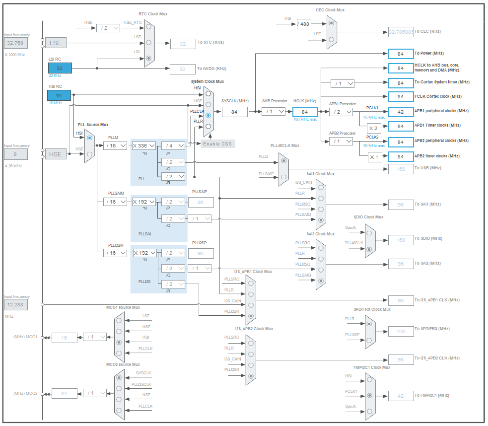
Under clock configuration main tab.
4. Configure the project
![]() 5min
5min
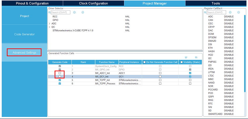
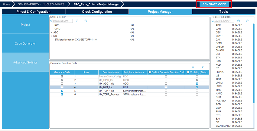
Under the project manager main tab, and the advanced settings tab, as we do not need the ADC and I2C initialization functions (handled by the BSP drivers), uncheck generate code for the MX_ADC1_Init and MX_I2C1_Init.
5. Generate code
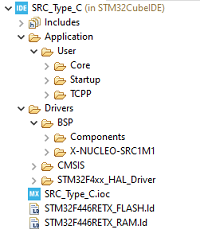
Save your file with Ctrl+s and select generate code if prompted. You can also generate code from the STM32CubeIDE menu, clicking on project/generate code, or by pressing alt+K.
In this project, different folders can be found:
- The core folder contains the source files for the core of the project.
- The drivers folder contains the HAL drivers for the STM32, and the BSP for the Nucleo board and X-NUCLEO-SRC1M1 shield.
6. Configure the shield's jumpers
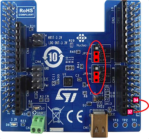
Place the jumpers on the X-NUCLEO-SRC1M1 shield as shown in the picture.
On the NUCLEO-F446, place a link between PA3 (CN10 - 37) and PC4 (CN10 - 34).
This X-NUCLEO-SRC1M1 shield default configuration allows SINK to source up to 0.5 A at 5 V.
Plug an external 5 V source with current capability >0.6 A into the green "source" connector.
The current sense resistor R4 is 7 mOhms, then TCPP02 current protection level is 6A. Refer to TCPP02-M18 datasheet[6].
With this configuration, the board is powered by the ST-Link of the Nucleo board.
If you want to power your system from the external power supply connected to the "source" terminal, and not from the ST-Link, add the JP1 jumpers between 1-2 and 3-4.
7. Compile and run the application
The compilation must be performed without errors or warnings.
Build the application, clicking on the ![]() button (or select project/build project).
button (or select project/build project).
Run the application, clicking on the ![]() button (or select run/run).
button (or select run/run).
8. Evaluate the application
![]() 5min
5min
Vbus is active 120 ms after plugging a USB Type-C® source device.
Vbus is immediately shut down and placed in safe mode (0 V) when unplugging the sink device.
During connection, if an overcurrent or malfunction is detected, the source is placed in safe mode (0V) and needs a disconnection/reconnection to restart.
9. Information focus: Code inserted by the software pack
By enabling the software pack in section 3.6, the code below has been added automatically in following files:
| app_tcpp.h |
/* Includes ------------------------------------------------------------------*/
#include "main.h"
#include "stm32f4xx_hal.h"

/* Exported functions --------------------------------------------------------*/
void MX_TCPP_Init(void);
void MX_TCPP_Process(void);

void USBnoPD_TCPPFaultHandling(void);
void TIM2_IRQHandler(void);
void DMA2_Stream0_IRQHandler(void);

/* Exported types ------------------------------------------------------------*/
typedef enum
{
  USBnoPD_CC1 = 0u,
  USBnoPD_CC2
} USBnoPD_CCTypeDef;

typedef enum
{
  USBnoPD_State_DETACHED = 0u, /* IDLE, nothing connected         */
  USBnoPD_State_ATTACHING,     /* Attachment ongoing - debouncing */
  USBnoPD_State_ATTACHED,      /* Attached                        */
  USBnoPD_State_DETACHING,     /* Detachment ongoing - debouncing */
  USBnoPD_State_DISCHARGING,   /* Vbus discharge ongoing          */
  USBnoPD_State_FAULT          /* Hardware fault                  */
} USBnoPD_StatesTypeDef;

typedef enum
{
  USBnoPD_ADC_Index_CC1 = 0u,  /* CC1 index in adc buffer    */
  USBnoPD_ADC_Index_CC2,       /* CC2 index in adc buffer    */
  USBnoPD_ADC_Index_VBUSC,     /* VBus index in adc buffer   */
  USBnoPD_ADC_Index_ISENSE,    /* Isense index in adc buffer */
  USBnoPD_ADC_Index_VPROV      /* Vprov index in adc buffer  */
} USBnoPD_ADCBufIDTypeDef;

/* Exported constants --------------------------------------------------------*/
#define USBNOPD_ADC_USED_CHANNELS     5u      /* Number of used ADC channels                                   */

#define USBNOPD_CC_VOLTAGE_MAXRA      800u    /* CC line Max voltage when Ra is connected (in mV)              */
#define USBNOPD_CC_VOLTAGE_MINRD      850u    /* CC line Min voltage when connected to Rd (in mV)              */
#define USBNOPD_CC_VOLTAGE_MAXRD      2450u   /* CC line Max voltage when connected to Rd (in mV)              */
#define USBNOPD_CC_VOLTAGE_MINOPEN    2750u   /* CC line Minimum voltage when not connected (in mV)            */
#define USBNOPD_VBUS_VOLTAGE_MAX      5500u   /* Vbus Maximum allowed voltage (in mV)                          */
#define USBNOPD_VPROV_VOLTAGE_MIN     4500u   /* Vprov Minimum voltage (in mV)                                 */
#define USBNOPD_VSAFE_VOLTAGE_MAX     100u    /* Vbus safe voltage to end vbus discharge (in mV)               */

#define USBNOPD_SRC1M1_NORA           0u      /* No voltage divider on CC lines                                */
#define USBNOPD_SRC1M1_NORB           0u      /* No voltage divider on CC lines                                */

#define USBNOPD_DEBOUNCE_ATTACH_TICKS 120u    /* Number of ticks needed to complete attaching state debouncing */
#define USBNOPD_DEBOUNCE_DETACH_TICKS 10u      /* Number of ticks needed to complete detaching state debouncing*/

#define BSP_USBPD_PWR_DONT_WAIT_VBUSOFF_DISCHARGE 1u

#define GREEN_LED_GPIO_Port           GPIOA
#define GREEN_LED_Pin                 GPIO_PIN_5

#ifdef __cplusplus
}
#endif
|
| app_tcpp.c |
/* Includes ------------------------------------------------------------------*/
#include "app_tcpp.h"
#include "src1m1_usbpd_pwr.h"
#include "stm32f4xx_hal_tim.h"
#include "stm32f4xx_hal_adc.h"
#include "stm32f4xx_hal_i2c.h"
#include "stm32f4xx_hal_i2c_ex.h"

/* Private variables ---------------------------------------------------------*/

ADC_HandleTypeDef hadc1;
DMA_HandleTypeDef hdma_adc1;
TIM_HandleTypeDef htim2;

USBnoPD_StatesTypeDef USBnoPD_State =                                  USBnoPD_State_DETACHED;
uint16_t USBnoPD_adc_buffer[USBNOPD_ADC_USED_CHANNELS] =               {0};
uint16_t USBnoPD_adc_buffer_filtered[USBNOPD_ADC_USED_CHANNELS];
uint16_t USBnoPD_adc_converted_buffer[USBNOPD_ADC_USED_CHANNELS] =     {0};
uint16_t USBnoPD_debounce_counter =                                    0;
uint8_t USBnoPD_activeCC =                                             USBnoPD_CC1; /* Default */

/* Maximum digital value of the ADC output (12 Bits resolution)
   To convert ADC measurement to an absolute voltage value:
   VCHANNELx = ADCx_DATA x (VDD/ADC_FULL_SCALE)
  */
#define ADC_FULL_SCALE       (0x0FFFU)

/* Private function prototypes -----------------------------------------------*/

static void USBnoPD_GPIO_Init(void);
static void USBnoPD_DMA_Init(void);
static void USBnoPD_ADC1_Init(void);
static void USBnoPD_TIM2_Init(void);
static uint32_t USBnoPD_TCPP0203_ConvertADCDataToVoltage(uint32_t ADCData, uint32_t Ra, uint32_t Rb);
static int32_t USBnoPD_TCPP0203_ConvertADCDataToCurrent(uint32_t ADCData, uint32_t Ga, uint32_t Rs);
static void USBnoPD_ProcessADC(void);
static void USBnoPD_IncrementDebounceCount(void);
static void USBnoPD_StateMachineRun(void);


void MX_TCPP_Init(void)
{

  USBnoPD_GPIO_Init();
  USBnoPD_DMA_Init();
  USBnoPD_ADC1_Init();
  USBnoPD_TIM2_Init();

  HAL_GPIO_WritePin(GREEN_LED_GPIO_Port, GREEN_LED_Pin, GPIO_PIN_RESET);
  HAL_GPIO_WritePin(TCPP0203_PORT0_ENABLE_GPIO_PORT, TCPP0203_PORT0_ENABLE_GPIO_PIN, GPIO_PIN_SET);

  BSP_USBPD_PWR_Init(USBPD_PWR_TYPE_C_PORT_1);
  BSP_USBPD_PWR_SetPowerMode(USBPD_PWR_TYPE_C_PORT_1, USBPD_PWR_MODE_NORMAL);

  HAL_ADC_Start_DMA(&hadc1, (uint32_t *)&USBnoPD_adc_buffer, USBNOPD_ADC_USED_CHANNELS);
  USBnoPD_State = USBnoPD_State_DETACHED;
}

void MX_TCPP_Process(void)
{
  USBnoPD_StateMachineRun();
}


/**
  * @brief GPIO Initialization Function
  * @param None
  * @retval None
  */
static void USBnoPD_GPIO_Init(void)
{
  GPIO_InitTypeDef GPIO_InitStruct = {0};

  /* GPIO Ports Clock Enable */
  __HAL_RCC_GPIOC_CLK_ENABLE();
  __HAL_RCC_GPIOA_CLK_ENABLE();
  __HAL_RCC_GPIOB_CLK_ENABLE();

#ifdef GREEN_LED_GPIO_Port
  /*Configure GPIO pin : GREEN_LED_Pin */
  /*Configure GPIO pin Output Level */
  HAL_GPIO_WritePin(GREEN_LED_GPIO_Port, GREEN_LED_Pin, GPIO_PIN_RESET);
  GPIO_InitStruct.Pin = GREEN_LED_Pin;
  GPIO_InitStruct.Mode = GPIO_MODE_OUTPUT_PP;
  GPIO_InitStruct.Pull = GPIO_NOPULL;
  GPIO_InitStruct.Speed = GPIO_SPEED_FREQ_LOW;
  HAL_GPIO_Init(GREEN_LED_GPIO_Port, &GPIO_InitStruct);
#endif

  /*Configure GPIO pin : FLG_Pin */
  GPIO_InitStruct.Pin = TCPP0203_PORT0_FLG_GPIO_PIN;
  GPIO_InitStruct.Mode = GPIO_MODE_IT_RISING;
  GPIO_InitStruct.Pull = GPIO_NOPULL;
  HAL_GPIO_Init(TCPP0203_PORT0_FLG_GPIO_PORT, &GPIO_InitStruct);

  /*Configure GPIO pin : ENABLE_Pin */
  /*Configure GPIO pin Output Level */
  HAL_GPIO_WritePin(TCPP0203_PORT0_ENABLE_GPIO_PORT, TCPP0203_PORT0_ENABLE_GPIO_PIN, GPIO_PIN_RESET);
  GPIO_InitStruct.Pin = TCPP0203_PORT0_ENABLE_GPIO_PIN;
  GPIO_InitStruct.Mode = GPIO_MODE_OUTPUT_PP;
  GPIO_InitStruct.Pull = GPIO_NOPULL;
  GPIO_InitStruct.Speed = GPIO_SPEED_FREQ_LOW;
  HAL_GPIO_Init(TCPP0203_PORT0_ENABLE_GPIO_PORT, &GPIO_InitStruct);

  /*Configure GPIO pins : CC1 */
  GPIO_InitStruct.Pin = USBNOPD_PORT0_CC1_GPIO_PIN;
  GPIO_InitStruct.Mode = GPIO_MODE_ANALOG;
  GPIO_InitStruct.Pull = GPIO_NOPULL;
  HAL_GPIO_Init(USBNOPD_PORT0_CC1_GPIO_PORT, &GPIO_InitStruct);

  /*Configure GPIO pins : CC2 */
  GPIO_InitStruct.Pin = USBNOPD_PORT0_CC2_GPIO_PIN;
  GPIO_InitStruct.Mode = GPIO_MODE_ANALOG;
  GPIO_InitStruct.Pull = GPIO_NOPULL;
  HAL_GPIO_Init(USBNOPD_PORT0_CC2_GPIO_PORT, &GPIO_InitStruct);

  /*Configure GPIO pins : VBUS */
  GPIO_InitStruct.Pin = USBNOPD_PORT0_VBUS_GPIO_PIN;
  GPIO_InitStruct.Mode = GPIO_MODE_ANALOG;
  GPIO_InitStruct.Pull = GPIO_NOPULL;
  HAL_GPIO_Init(USBNOPD_PORT0_VBUS_GPIO_PORT, &GPIO_InitStruct);

  /*Configure GPIO pins : VBUSPROV */
  GPIO_InitStruct.Pin = USBNOPD_PORT0_VBUSPROV_GPIO_PIN;
  GPIO_InitStruct.Mode = GPIO_MODE_ANALOG;
  GPIO_InitStruct.Pull = GPIO_NOPULL;
  HAL_GPIO_Init(USBNOPD_PORT0_VBUSPROV_GPIO_PORT, &GPIO_InitStruct);

  /*Configure GPIO pins : IANA */
  GPIO_InitStruct.Pin = USBNOPD_PORT0_IANA_GPIO_PIN;
  GPIO_InitStruct.Mode = GPIO_MODE_ANALOG;
  GPIO_InitStruct.Pull = GPIO_NOPULL;
  HAL_GPIO_Init(USBNOPD_PORT0_IANA_GPIO_PORT, &GPIO_InitStruct);

  /* EXTI interrupt init*/
  HAL_NVIC_SetPriority(TCPP0203_PORT0_FLG_EXTI_IRQN, 0, 0);
  HAL_NVIC_EnableIRQ(TCPP0203_PORT0_FLG_EXTI_IRQN);
}

/**
  * @brief ADC1 Initialization Function
  * @param None
  * @retval None
  */
static void USBnoPD_ADC1_Init(void)
{
  ADC_ChannelConfTypeDef sConfig = {0};
  __HAL_RCC_ADC1_CLK_ENABLE();

  /** Configure the global features of the ADC (Clock, Resolution, Data Alignment and number of conversion)*/
  hadc1.Instance = ADC1;
  hadc1.Init.ClockPrescaler = ADC_CLOCK_SYNC_PCLK_DIV4;
  hadc1.Init.Resolution = ADC_RESOLUTION_12B;
  hadc1.Init.ScanConvMode = ENABLE;
  hadc1.Init.ContinuousConvMode = ENABLE;
  hadc1.Init.DiscontinuousConvMode = DISABLE;
  hadc1.Init.ExternalTrigConvEdge = ADC_EXTERNALTRIGCONVEDGE_NONE;
  hadc1.Init.ExternalTrigConv = ADC_SOFTWARE_START;
  hadc1.Init.DataAlign = ADC_DATAALIGN_RIGHT;
  hadc1.Init.NbrOfConversion = 5;
  hadc1.Init.DMAContinuousRequests = ENABLE;
  hadc1.Init.EOCSelection = ADC_EOC_SINGLE_CONV;
  if (HAL_ADC_Init(&hadc1) != HAL_OK)
  {
    Error_Handler();
  }
  /** Configure for the selected ADC regular channel its corresponding rank in the sequencer and its sample time.
  */
  sConfig.Channel = ADC_CHANNEL_10;
  sConfig.Rank = 1;
  sConfig.SamplingTime = ADC_SAMPLETIME_84CYCLES;
  if (HAL_ADC_ConfigChannel(&hadc1, &sConfig) != HAL_OK)
  {
    Error_Handler();
  }
  /** Configure for the selected ADC regular channel its corresponding rank in the sequencer and its sample time.
  */
  sConfig.Channel = ADC_CHANNEL_4;
  sConfig.Rank = 2;
  if (HAL_ADC_ConfigChannel(&hadc1, &sConfig) != HAL_OK)
  {
    Error_Handler();
  }
  /** Configure for the selected ADC regular channel its corresponding rank in the sequencer and its sample time.
  */
  sConfig.Channel = ADC_CHANNEL_0;
  sConfig.Rank = 3;
  if (HAL_ADC_ConfigChannel(&hadc1, &sConfig) != HAL_OK)
  {
    Error_Handler();
  }
  /** Configure for the selected ADC regular channel its corresponding rank in the sequencer and its sample time.
  */
  sConfig.Channel = ADC_CHANNEL_11;
  sConfig.Rank = 4;
  if (HAL_ADC_ConfigChannel(&hadc1, &sConfig) != HAL_OK)
  {
    Error_Handler();
  }
  /** Configure for the selected ADC regular channel its corresponding rank in the sequencer and its sample time.
  */
  sConfig.Channel = ADC_CHANNEL_1;
  sConfig.Rank = 5;
  if (HAL_ADC_ConfigChannel(&hadc1, &sConfig) != HAL_OK)
  {
    Error_Handler();
  }
}

/**
  * @brief TIM2 Initialization Function
  * @param None
  * @retval None
  */
static void USBnoPD_TIM2_Init(void)
{
  TIM_ClockConfigTypeDef sClockSourceConfig = {0};
  TIM_MasterConfigTypeDef sMasterConfig = {0};
  __HAL_RCC_TIM2_CLK_ENABLE();
  htim2.Instance = TIM2;
  htim2.Init.Prescaler = 2099;
  htim2.Init.CounterMode = TIM_COUNTERMODE_UP;
  htim2.Init.Period = 39;
  htim2.Init.ClockDivision = TIM_CLOCKDIVISION_DIV1;
  htim2.Init.AutoReloadPreload = TIM_AUTORELOAD_PRELOAD_ENABLE;
  if (HAL_TIM_Base_Init(&htim2) != HAL_OK)
  {
    Error_Handler();
  }
  sClockSourceConfig.ClockSource = TIM_CLOCKSOURCE_INTERNAL;
  if (HAL_TIM_ConfigClockSource(&htim2, &sClockSourceConfig) != HAL_OK)
  {
    Error_Handler();
  }
  sMasterConfig.MasterOutputTrigger = TIM_TRGO_RESET;
  sMasterConfig.MasterSlaveMode = TIM_MASTERSLAVEMODE_DISABLE;
  if (HAL_TIMEx_MasterConfigSynchronization(&htim2, &sMasterConfig) != HAL_OK)
  {
    Error_Handler();
  }
  HAL_NVIC_SetPriority(TIM2_IRQn, 0, 0);
  HAL_NVIC_EnableIRQ(TIM2_IRQn);
}

/**
  * Enable DMA controller clock
  */
static void USBnoPD_DMA_Init(void)
{
  /* DMA controller clock enable */
  __HAL_RCC_DMA2_CLK_ENABLE();
  /* DMA interrupt init */
  /* DMA2_Stream0_IRQn interrupt configuration */
  HAL_NVIC_SetPriority(DMA2_Stream0_IRQn, 0, 0);
  HAL_NVIC_EnableIRQ(DMA2_Stream0_IRQn);

  /* ADC1 DMA Init */
  /* ADC1 Init */
  hdma_adc1.Instance = DMA2_Stream0;
  hdma_adc1.Init.Channel = DMA_CHANNEL_0;
  hdma_adc1.Init.Direction = DMA_PERIPH_TO_MEMORY;
  hdma_adc1.Init.PeriphInc = DMA_PINC_DISABLE;
  hdma_adc1.Init.MemInc = DMA_MINC_ENABLE;
  hdma_adc1.Init.PeriphDataAlignment = DMA_PDATAALIGN_HALFWORD;
  hdma_adc1.Init.MemDataAlignment = DMA_MDATAALIGN_HALFWORD;
  hdma_adc1.Init.Mode = DMA_CIRCULAR;
  hdma_adc1.Init.Priority = DMA_PRIORITY_LOW;
  hdma_adc1.Init.FIFOMode = DMA_FIFOMODE_DISABLE;
  if (HAL_DMA_Init(&hdma_adc1) != HAL_OK)
  {
    Error_Handler();
  }
  __HAL_LINKDMA(&hadc1,DMA_Handle,hdma_adc1);
}

/**
  * @brief  Main state machine
  * @param  none
  * @retval none
  */
static void USBnoPD_StateMachineRun(void)
{
  switch(USBnoPD_State)
  {
    case USBnoPD_State_DETACHED:      /* IDLE, nothing connected         */
      /* Transition to next state */
      if (USBnoPD_adc_converted_buffer[USBnoPD_ADC_Index_VPROV] > USBNOPD_VPROV_VOLTAGE_MIN)
      {
        /* Connection detected on CC1 */
        if ((USBnoPD_adc_converted_buffer[USBnoPD_ADC_Index_CC1] > USBNOPD_CC_VOLTAGE_MINRD) &&
            (USBnoPD_adc_converted_buffer[USBnoPD_ADC_Index_CC1] < USBNOPD_CC_VOLTAGE_MAXRD) &&
            (USBnoPD_adc_converted_buffer[USBnoPD_ADC_Index_CC2] < USBNOPD_CC_VOLTAGE_MAXRA ||
             USBnoPD_adc_converted_buffer[USBnoPD_ADC_Index_CC2] > USBNOPD_CC_VOLTAGE_MINOPEN))
        {
          /* Reset debouncing counter */
          USBnoPD_debounce_counter = 0u;

          /* Start the debouncing timer */
          HAL_TIM_Base_Start_IT(&htim2);

          /* Active CC is now CC1 */
          USBnoPD_activeCC = USBnoPD_CC1;

          /* Go to attaching state */
          USBnoPD_State = USBnoPD_State_ATTACHING;
        }
        /* Connection detected on CC2 */
        else if ((USBnoPD_adc_converted_buffer[USBnoPD_ADC_Index_CC2] > USBNOPD_CC_VOLTAGE_MINRD) &&
                 (USBnoPD_adc_converted_buffer[USBnoPD_ADC_Index_CC2] < USBNOPD_CC_VOLTAGE_MAXRD) &&
                 (USBnoPD_adc_converted_buffer[USBnoPD_ADC_Index_CC1] < USBNOPD_CC_VOLTAGE_MAXRA ||
                  USBnoPD_adc_converted_buffer[USBnoPD_ADC_Index_CC1] > USBNOPD_CC_VOLTAGE_MINOPEN))
        {
          /* Reset debouncing counter */
          USBnoPD_debounce_counter = 0u;

          /* Start the debouncing timer */
          HAL_TIM_Base_Start_IT(&htim2);

          /* Active CC is now CC2 */
          USBnoPD_activeCC = USBnoPD_CC2;

          /* Go to attaching state */
          USBnoPD_State = USBnoPD_State_ATTACHING;
        }
      }
      break;

    case USBnoPD_State_ATTACHING:     /* Attachment ongoing - debouncing */
      /* If a glitch is detected, reset debounce counter and go to detached state*/
      if (((USBnoPD_activeCC == USBnoPD_CC1) &&
           ((USBnoPD_adc_converted_buffer[USBnoPD_ADC_Index_CC1] > USBNOPD_CC_VOLTAGE_MAXRD) ||
            (USBnoPD_adc_converted_buffer[USBnoPD_ADC_Index_CC1] < USBNOPD_CC_VOLTAGE_MINRD))) ||
          ((USBnoPD_activeCC == USBnoPD_CC2) &&
           ((USBnoPD_adc_converted_buffer[USBnoPD_ADC_Index_CC2] > USBNOPD_CC_VOLTAGE_MAXRD) ||
            (USBnoPD_adc_converted_buffer[USBnoPD_ADC_Index_CC2] < USBNOPD_CC_VOLTAGE_MINRD))))
      {
        /* Reset debouncing counter */
        USBnoPD_debounce_counter = 0u;

        /* Stop the debouncing timer */
        HAL_TIM_Base_Stop_IT(&htim2);

        /* Go to attaching state */
        USBnoPD_State = USBnoPD_State_DETACHED;
      }
      /* If debouncing is over */
      else if (USBnoPD_debounce_counter >= USBNOPD_DEBOUNCE_ATTACH_TICKS)
      {
        /* Reset debouncing counter */
        USBnoPD_debounce_counter = 0u;

        /* Stop the debouncing timer */
        HAL_TIM_Base_Stop_IT(&htim2);

        /* Turn ON Vbus */
        BSP_USBPD_PWR_VBUSDischargeOff(USBPD_PWR_TYPE_C_PORT_1);
        BSP_USBPD_PWR_VBUSOn(USBPD_PWR_TYPE_C_PORT_1);

        /* Turn on green LED to indicate source is ON */
        HAL_GPIO_WritePin(GREEN_LED_GPIO_Port, GREEN_LED_Pin, GPIO_PIN_SET);

        /* Go to attached state */
        USBnoPD_State = USBnoPD_State_ATTACHED;
      }
      break;

    case USBnoPD_State_ATTACHED:      /* Attached                        */
      /* If we detect a fault on Vbus or Vprov and
         CC voltage still correspond to an attached state */
      if (((USBnoPD_adc_converted_buffer[USBnoPD_ADC_Index_VBUSC]  > USBNOPD_VBUS_VOLTAGE_MAX) ||
           (USBnoPD_adc_converted_buffer[USBnoPD_ADC_Index_VPROV] < USBNOPD_VPROV_VOLTAGE_MIN))&&
          (((USBnoPD_adc_converted_buffer[USBnoPD_ADC_Index_CC1] > USBNOPD_CC_VOLTAGE_MINRD) &&
            (USBnoPD_adc_converted_buffer[USBnoPD_ADC_Index_CC1] < USBNOPD_CC_VOLTAGE_MAXRD))||
           ((USBnoPD_adc_converted_buffer[USBnoPD_ADC_Index_CC2] > USBNOPD_CC_VOLTAGE_MINRD) &&
            (USBnoPD_adc_converted_buffer[USBnoPD_ADC_Index_CC2] < USBNOPD_CC_VOLTAGE_MAXRD))))
      {
        /* Cut VBUS */
        BSP_USBPD_PWR_VBUSOff(USBPD_PWR_TYPE_C_PORT_1);
        BSP_USBPD_PWR_VBUSDischargeOn(USBPD_PWR_TYPE_C_PORT_1);

        /* Turn off green LED to indicate source is OFF */
        HAL_GPIO_WritePin(GREEN_LED_GPIO_Port, GREEN_LED_Pin, GPIO_PIN_RESET);

        /* Go to fault state */
        USBnoPD_State = USBnoPD_State_FAULT;
      }
      /* If a detachment is detected */
      else if (((USBnoPD_activeCC == USBnoPD_CC1) &&
                (USBnoPD_adc_converted_buffer[USBnoPD_ADC_Index_CC1] > USBNOPD_CC_VOLTAGE_MAXRD)) ||
               ((USBnoPD_activeCC == USBnoPD_CC2) &&
                (USBnoPD_adc_converted_buffer[USBnoPD_ADC_Index_CC2] > USBNOPD_CC_VOLTAGE_MAXRD)))
      {
        /* Reset debouncing counter */
        USBnoPD_debounce_counter = 0u;

        /* Start the debouncing timer */
        HAL_TIM_Base_Start_IT(&htim2);

        /* Go to detaching state */
        USBnoPD_State = USBnoPD_State_DETACHING;
      }
      break;

    case USBnoPD_State_DETACHING:     /* Detachment ongoing - debouncing */
      /* Detach abort */
      if (((USBnoPD_activeCC == USBnoPD_CC1) &&
           (USBnoPD_adc_converted_buffer[USBnoPD_ADC_Index_CC1] < USBNOPD_CC_VOLTAGE_MAXRD)) ||
          ((USBnoPD_activeCC == USBnoPD_CC2) &&
           (USBnoPD_adc_converted_buffer[USBnoPD_ADC_Index_CC2] < USBNOPD_CC_VOLTAGE_MAXRD)))
      {
        /* Reset debouncing counter */
        USBnoPD_debounce_counter = 0u;

        /* Stop the debouncing timer */
        HAL_TIM_Base_Stop_IT(&htim2);

        /* Go back to attached state */
        USBnoPD_State = USBnoPD_State_ATTACHED;
      }
      /* If debouncing is over */
      else if (USBnoPD_debounce_counter >= USBNOPD_DEBOUNCE_DETACH_TICKS)
      {
        /* Reset debouncing counter */
        USBnoPD_debounce_counter = 0u;

        /* Stop the debouncing timer */
        HAL_TIM_Base_Stop_IT(&htim2);

        /* Turn OFF Vbus */
        BSP_USBPD_PWR_VBUSOff(USBPD_PWR_TYPE_C_PORT_1);
        BSP_USBPD_PWR_VBUSDischargeOn(USBPD_PWR_TYPE_C_PORT_1);

        /* Turn off green LED to indicate source is OFF */
        HAL_GPIO_WritePin(GREEN_LED_GPIO_Port, GREEN_LED_Pin, GPIO_PIN_RESET);

        /* Go to discharging state */
        USBnoPD_State = USBnoPD_State_DISCHARGING;
      }
      break;

    case USBnoPD_State_DISCHARGING:   /* Vbus discharge after detach ongoing */
      /* If Vbus is considered measured as 0v */
      if (USBnoPD_adc_converted_buffer[USBnoPD_ADC_Index_VBUSC]  < USBNOPD_VSAFE_VOLTAGE_MAX)
      {
        /* Reset debouncing counter */
        USBnoPD_debounce_counter = 0u;

        /* Stop the debouncing timer */
        HAL_TIM_Base_Stop_IT(&htim2);

        /* Stop Vbus discharge */
        BSP_USBPD_PWR_VBUSDischargeOff(USBPD_PWR_TYPE_C_PORT_1);

        /* Turn off green LED to indicate source is OFF */
        HAL_GPIO_WritePin(GREEN_LED_GPIO_Port, GREEN_LED_Pin, GPIO_PIN_RESET);

        /* Go to detached state */
        USBnoPD_State = USBnoPD_State_DETACHED;
      }
      break;

    case USBnoPD_State_FAULT:         /* Hardware fault                  */
      /* In case of a fault, do nothing until a detach is detected and Vbus is at 0v */
      if ((((USBnoPD_activeCC == USBnoPD_CC1) &&
            (USBnoPD_adc_converted_buffer[USBnoPD_ADC_Index_CC1] > USBNOPD_CC_VOLTAGE_MINOPEN)) ||
           ((USBnoPD_activeCC == USBnoPD_CC2) &&
            (USBnoPD_adc_converted_buffer[USBnoPD_ADC_Index_CC2] > USBNOPD_CC_VOLTAGE_MINOPEN))) &&
          (USBnoPD_adc_converted_buffer[USBnoPD_ADC_Index_VBUSC]  < USBNOPD_VSAFE_VOLTAGE_MAX))
      {
        /* Stop Vbus discharge */
        BSP_USBPD_PWR_VBUSDischargeOff(USBPD_PWR_TYPE_C_PORT_1);

        /* Go to detached state */
        USBnoPD_State = USBnoPD_State_DETACHED;
      }
      break;

  default:                            /* Should not happen               */
    /* Cut VBUS */
    BSP_USBPD_PWR_VBUSOff(USBPD_PWR_TYPE_C_PORT_1);
    BSP_USBPD_PWR_VBUSDischargeOn(USBPD_PWR_TYPE_C_PORT_1);

    /* Turn off green LED to indicate source is OFF */
    HAL_GPIO_WritePin(GREEN_LED_GPIO_Port, GREEN_LED_Pin, GPIO_PIN_RESET);

    /* Go to fault state */
    USBnoPD_State = USBnoPD_State_FAULT;
    break;
  }
  /* 1ms delay between each state machine iterations */
  HAL_Delay(1);
}

/**
  * @brief  Calculate the VBUS voltage level corresponding to ADC raw converted data.
  * @note   Voltage level is measured though a voltage divider
  *  Example :
  *  Voltage -- Ra ----.-   ^
  *                    |    |
  *                    Rb   | vadc = VBUS * Rb /(Ra + Rb)
  *                    |    |
  *                   GND   |
  * vadc = raw_data * (ADC_FULL_SCALE / VDD)
  * @param  ADCData  ADC raw converted data (resolution 12 bits)
  * @param  Ra       value of Ra resistance
  * @param  Rb       value of Rb resistance
  * @retval analog voltage (unit: mV)
  */
static uint32_t USBnoPD_TCPP0203_ConvertADCDataToVoltage(uint32_t ADCData, uint32_t Ra, uint32_t Rb)
{
  uint32_t voltage;
  uint32_t vadc;

  /* Convert ADC RAW data to voltage */
  vadc = (ADCData * VDD_VALUE) / ADC_FULL_SCALE;

  /* If no Ra or Rb are defined, return vadc directly */
  if ((Ra == 0u) && (Rb == 0u))
  {
    voltage = vadc;
  }
  else
  {
    /* Avoid dividing by zero */
    if (Rb == 0u)
    {
      voltage = 0u;
    }
    else
    {
      /* Apply voltage divider */
      voltage = vadc * (Ra + Rb) / Rb;
    }
  }
  return voltage;
}

/**
  * @brief  Calculate the VBUS current level corresponding to ADC raw converted data.
  * @note   ADC measurement provides measurement on IANA pin.
  * @param  ADCData  ADC raw converted data (resolution 12 bits)
  * @param  Ga       value of TCPP0X Iana gain in V/V
  * @param  Rs       value of shunt resistor in milliohm
  * @retval VBUS analog current (unit: mA)
  */
static int32_t USBnoPD_TCPP0203_ConvertADCDataToCurrent(uint32_t ADCData, uint32_t Ga, uint32_t Rs)
{
  int32_t current;
  uint32_t vadc;

  /* Avoid dividing by zero */
  if ((Ga == 0u) || (Rs == 0u))
  {
    current = 0u;
  }
  else
  {
    vadc = (ADCData * VDD_VALUE) / ADC_FULL_SCALE;
    current = (int32_t)((vadc * 1000u) / (Ga * Rs));
  }

  return current;
}

/**
  * @brief  Process the ADC values and update USBnoPD_adc_converted_buffer with measured values.
  * @param  none
  * @retval none
  */
void USBnoPD_ProcessADC(void)
{
  /* Perform ADC Filtering */
  for (uint8_t i = 0u; i < USBNOPD_ADC_USED_CHANNELS; i++)
  {
    USBnoPD_adc_buffer_filtered[i] = (USBnoPD_adc_buffer_filtered[i] + USBnoPD_adc_buffer[i]) >> 1u;
  }
  /* Update the voltage buffer by converting the filtered values */
  USBnoPD_adc_converted_buffer[USBnoPD_ADC_Index_CC1] =
    USBnoPD_TCPP0203_ConvertADCDataToVoltage(USBnoPD_adc_buffer_filtered[USBnoPD_ADC_Index_CC1],USBNOPD_SRC1M1_NORA,USBNOPD_SRC1M1_NORB);
  USBnoPD_adc_converted_buffer[USBnoPD_ADC_Index_CC2] =
    USBnoPD_TCPP0203_ConvertADCDataToVoltage(USBnoPD_adc_buffer_filtered[USBnoPD_ADC_Index_CC2],USBNOPD_SRC1M1_NORA,USBNOPD_SRC1M1_NORB);
  USBnoPD_adc_converted_buffer[USBnoPD_ADC_Index_VBUSC] =
    USBnoPD_TCPP0203_ConvertADCDataToVoltage(USBnoPD_adc_buffer_filtered[USBnoPD_ADC_Index_VBUSC],SRC1M1_VSENSE_RA,SRC1M1_VSENSE_RB);
  USBnoPD_adc_converted_buffer[USBnoPD_ADC_Index_ISENSE] =
    USBnoPD_TCPP0203_ConvertADCDataToCurrent(USBnoPD_adc_buffer_filtered[USBnoPD_ADC_Index_ISENSE],SRC1M1_ISENSE_GA,SRC1M1_ISENSE_RS);
  USBnoPD_adc_converted_buffer[USBnoPD_ADC_Index_VPROV] =
    USBnoPD_TCPP0203_ConvertADCDataToVoltage(USBnoPD_adc_buffer_filtered[USBnoPD_ADC_Index_VPROV],SRC1M1_VSENSE_RA,SRC1M1_VSENSE_RB);
}

/**
  * @brief  Increment debounce counter, used in timer IRQHandler
  * @param  none
  * @retval none
  */
void USBnoPD_IncrementDebounceCount(void)
{
  USBnoPD_debounce_counter++;
}

/**
  * @brief  Handle a fault raised by the TCPP (OCP), used by EXTI IRQHandler
  * @param  none
  * @retval none
  */
void USBnoPD_TCPPFaultHandling(void)
{
    /* Cut VBUS */
  BSP_USBPD_PWR_VBUSOff(USBPD_PWR_TYPE_C_PORT_1);
  BSP_USBPD_PWR_VBUSDischargeOn(USBPD_PWR_TYPE_C_PORT_1);

  /* Turn off green LED to indicate source is OFF */
  HAL_GPIO_WritePin(GREEN_LED_GPIO_Port, GREEN_LED_Pin, GPIO_PIN_RESET);

  /* Go to Fault state */
  USBnoPD_State = USBnoPD_State_FAULT;
}


/**
  * @brief This function handles EXTI line 4 interrupt.
  */
void EXTI4_IRQHandler(void)
{
  /* Handle TCPP FLGn fault flag (active LOW) */
  USBnoPD_TCPPFaultHandling();
  HAL_GPIO_EXTI_IRQHandler(TCPP0203_PORT0_FLG_GPIO_PIN);
}


/**
  * @brief This function handles TIM2 global interrupt.
  */
void TIM2_IRQHandler(void)
{
  /* Increment the debounce counter */
  USBnoPD_IncrementDebounceCount();
  HAL_TIM_IRQHandler(&htim2);
}


/**
  * @brief This function handles DMA2 stream0 global interrupt.
  */
void DMA2_Stream0_IRQHandler(void)
{
  /* Perform ADC processing */
  USBnoPD_ProcessADC();
  HAL_DMA_IRQHandler(&hdma_adc1);
}
|
10. Project with a custom board
This chapter describes how to build a USB PD source application using a custom board with any STM32 MCU with five ADC channels.
- As in the chapter 2, create the project.
- As in the chapter 3.1, clear the pinout.
- As per chapter 3.2, select the X-CUBE-TCPP software pack.
But do not select the board support for X-NUCLEO-SRC1M1 as your application is based on a custom board.
- Configure the ADC peripheral:
Five signals must be monitored to ensure proper and safe USB 3 A-5 V delivery:
CC1 and CC2 lines voltage, Vbus and Vprovider voltages and Iana, and the current through Vbus.
The ADC needs to be configured:
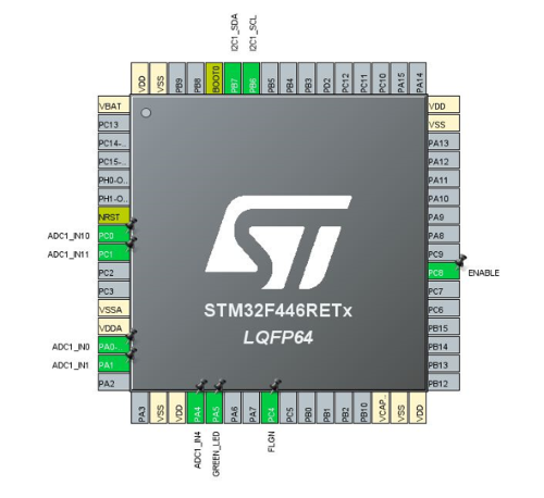
In the pin view, with a left click, select the pin PC0 and configure it as ADC1 Channel 10 (CC2).
Repeat the operation for PC1 as ADC1 Channel 11 (IANA); for PA0 as ADC1 Channel 0 (VBusc); for PA1 as ADC1 Channel 1(Vprov); and for PA4 as ADC1 Channel 4 (CC1).
Note: it is not mandatory to set their name as each value is stored in a table by the DMA in function of its rank.
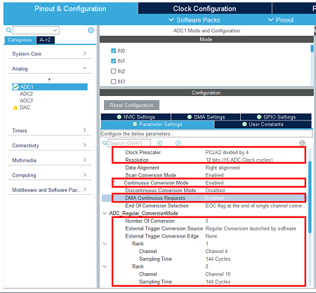
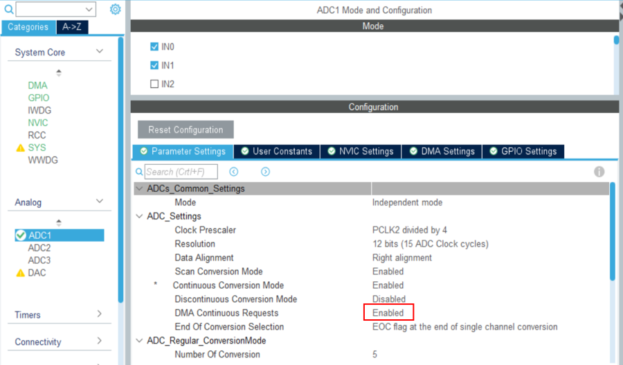
- In the analog section click on ADC and select, in the parameter settings tab:
Scan conversion mode: Enabled
Continuous conversion mode: Enabled
Number of conversions: 5
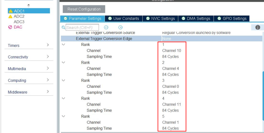
Define for each ADC input its channel and 84 cycles sampling time.
Rank 1: CC2: Channel 10
Rank 2: CC1: Channel 4
Rank 3: Vbus: Channel 0
Rank 4: Iana: Channel 11
Rank 5: Vprov: Channel 1
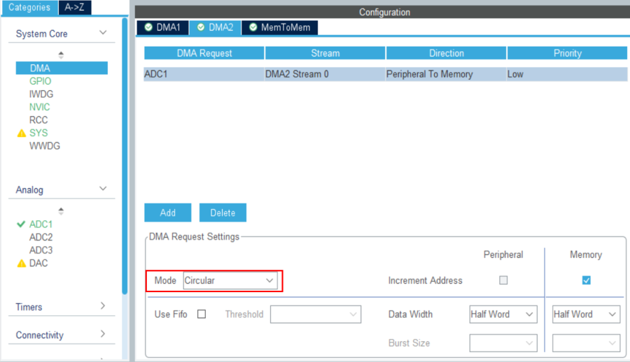
- Configure the DMA for ADC1:
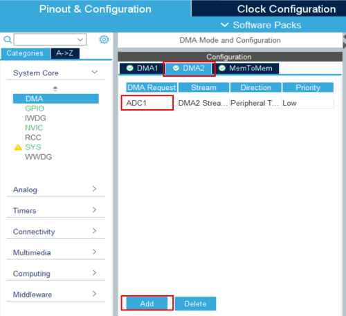
In the system core section, select the DMA, tab DMA2 click on "add" and select ADC1 in the DMA2 request column.
Set the DMA mode to circular.
Then back to the ADC1 parameters configuration, set DMA continuous requests to enabled.
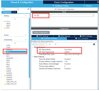
- Configure the I2C peripheral:
Enable the I2C connected to the TCPP02 I2C bus.
Set its speed in fast mode.
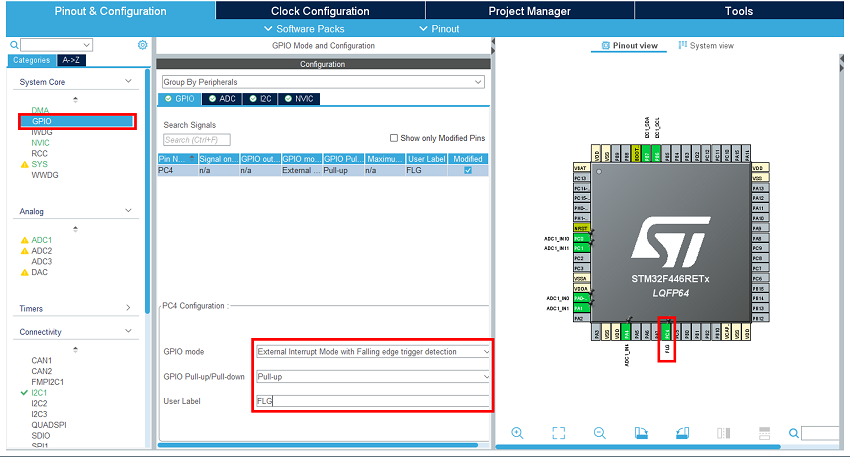
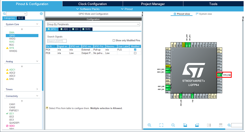
- Configure the GPIO:
Enable and configure the external interrupt input where the TCPP02 FLG signal is connected.
Select it in the pinout view.
In the GPIO category, set it as external interrupt mode with falling edge trigger detection.
Enable its pull-up.
In the pinout view, select the GPIO output for TCPP02 enable.
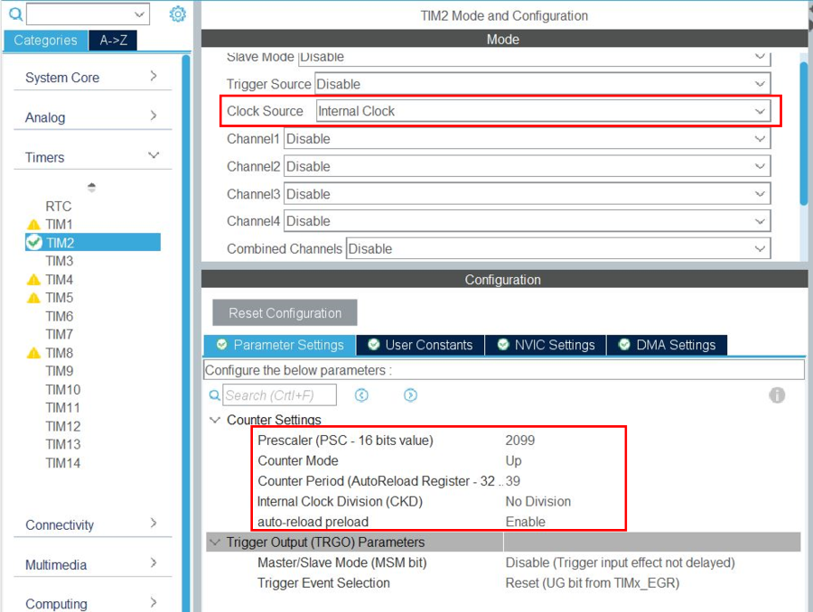
- Configure the timer:
In the timers section, select timer2: "TIM2", affect the "internal clock" as clock source.
In the parameter settings tab:
- Set the internal clock division to no division; then the timer peripheral frequency is 84 MHz.
- Set the prescaler value to 2099; then the timer counter frequency is 84 MHz / (2099+1) = 40 kHz.
- Set the counter period to 39; then the timer period is 40 kHz / (39+1) = 1 ms.
- Set auto-reload preload to enable.
- Set the internal clock division to no division; then the timer peripheral frequency is 84 MHz.
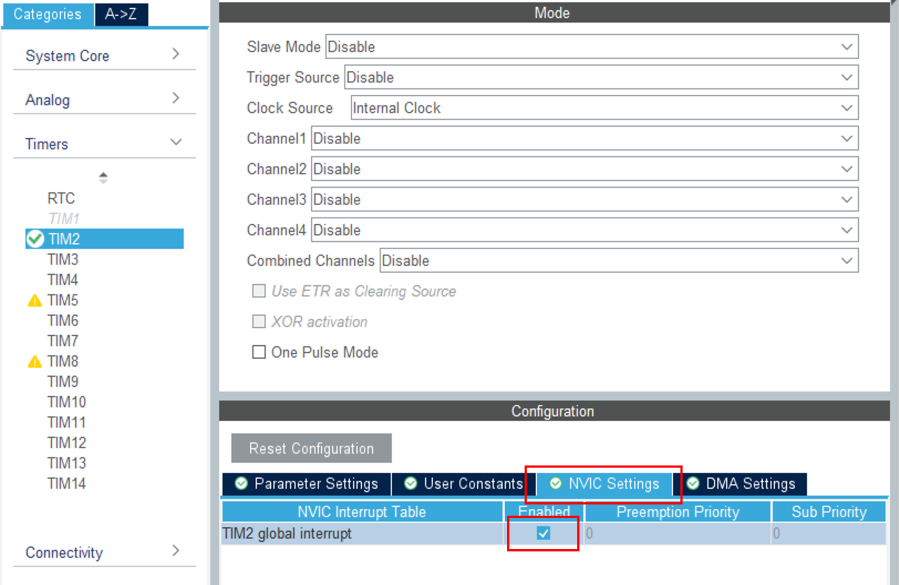
Finally, select the NVIC settings tab to enable the TIM2 global interrupt.
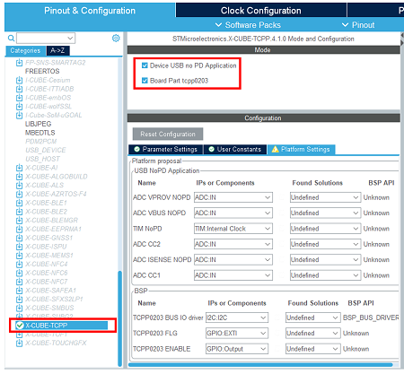
- Enable the software pack:
In the middleware category, select the X-CUBE-TCPP software pack and enable its application and Board part.
- Assign resources to the application requirements:
- As in the chapter 4, configure the project.
But in the advanced settings keep ADC and I2C initialization code generation.
- As in the chapter 5, generate the code.
- As in the chapter 7, compile and run the application.
You can find other applicative examples on GitHub: x-cube-tcpp
11. References
