1. Single shunt phase shift overview
In the context of a single shunt topology, the purpose of the phase-shifting is to shift one or two duty cycles to be able to sample the current signal in the boundary zones instead of inserting a distortion window.
The benefits are:
- Fewer commutations
- Less switching losses
2. Phase shift principle
Boundary zone 1:
- The firmware shifts on the right the smallest duty cycle by TMIN (minimum window time for sampling)
Boundary zone 2:
- The firmware shifts on the right the most middle duty cycle by TMIN (minimum window time for sampling)
Boundary zone 3:
- The firmware shifts on the right the smallest duty cycle and on the left the highest duty cycle by TMIN (minimum window time for sampling)
3. Peripheral usage
Phase-shifting needs the following peripherals to create the shifting. According to the advanced timer capabilities, one or two DMA channels will be used
| MCU | TIM | DMA | IRQ |
|---|---|---|---|
| F0 | TIM1 | DMA1_Ch5 DMA1_Ch4 | DMA1_Ch5 HT and TC |
| G0 | TIM1 | DMA1_Ch4 | DMA1_Ch4 HT and TC |
| F3 | TIM1 | DMA1_Ch4 | DMA1_Ch4 HT and TC |
| TIM8 | DMA1_Ch2 | DMA1_Ch2 HT and TC | |
| F4 | TIM1 | DMA2_stream4 DMA2_stream5 | DMA_stream5 HT and TC |
| TIM8 | DMA2_stream7 DMA2_stream1 | DMA_Stream1 HT and TC | |
| G4 | TIM1 | DMA1_Ch1 | DMA1_Ch1 HT and TC |
| TIM8 | DMA2_Ch1 | DMA2_Ch4 HT and TC | |
| L4 | TIM1 | DMA1_Ch4 | DMA1_Ch4 HT and TC |
| TIM8 | DMA2_Ch2 | DMA2_Ch2 HT and TC | |
| F7 | TIM1 | DMA2_stream4 | DMA2_Stream4 HT and TC |
| TIM8 | DMA2_stream7 | DMA2_Stream7 HT and TC |
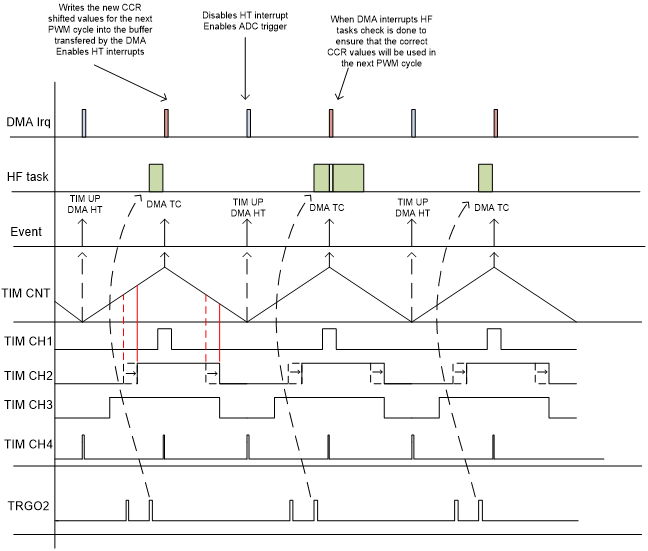
4. Single shunt phase shift scheduling example
6 channels advanced timer and execution rate = 1 (G0,G4,F3,L4,F7)
5. Single shunt phase shift in the STM32 MC SDK
Single shunt is implemented by r1_ps_pwm_fdbk.c (and .h) processed when the STM32 MC project uses a MCU.


