This message will disappear after all relevant tasks have been resolved.
Semantic MediaWiki
There are 1 incomplete or pending task to finish installation of Semantic MediaWiki. An administrator or user with sufficient rights can complete it. This should be done before adding new data to avoid inconsistencies.
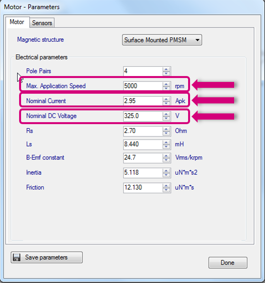
1. Max Rated Speed, Nominal Current and Nominal DC Voltage parameters
- Set the Max Rated Speed to the maximum motor speed according to the application specifications.
- Set the Nominal Current to the maximum peak current provided to each of the motor phases according to the motor specifications.
- Set the Nominal DC Voltage to the value of the DC bus provided to the inverter or the rectified value of AC input.
2. Pole pair (number) parameter
- The number of pole pairs is usually provided by the motor supplier, but in case it’s not or if you’d like to double-check it:
- Connect a DC power supply between two (of the three) motor phases and provide up to 5% of the expected nominal DC bus voltage. (You may also set the current protection to the nominal motor current.)
- Rotate the motor with your hands, you should notice a little resistance, otherwise:
- If you are not able to rotate the motor, decrease the applied voltage.
- If the motor does not generate any resistance, gradually increase the applied voltage.
- The number of rotor stable positions in one mechanical turn represents the number of pole pairs.
3. Stator resistance and inductance parameters
- Using the multimeter, measure the DC stator resistance phase-to-phase (Rs) and divide it by two.
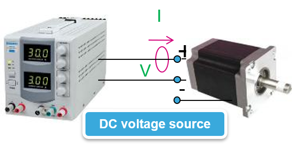
- Connect the DC voltage between two motor phases.
- Connect the oscilloscope voltage and current probes as shown in the figure.
- Increase the voltage up to the value where the current equals the nominal value, so the rotor aligns with the generated flux.
- Don’t move the rotor anymore.
- Disable the current protection of the DC voltage source.
- Unplug one terminal of the voltage source cable without switching it off.
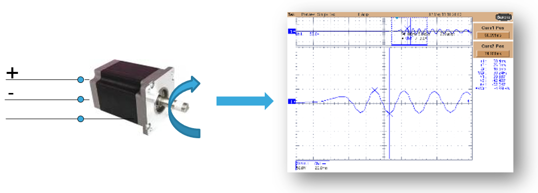
- Plug the voltage source rapidly and monitor on the scope the voltage and current waveform until you get something like the one shown in the figure.
- The measurement is good if the voltage can be assimilated to a step and the current increase such as I∞ * (1-e- t *L/R).
- Measure the time required for the current waveform to rise to 63%.
- This time is Ld/Rs constant. Multiply it by Rs and you’ll get the Ld value.
4. Back EMF constant Ke
- The Back-EMF constant represents the proportionality constant between the mechanical motor speed and the amplitude of the B-EMF induced into the motor phases:
- To measure Ke, it usually suffices to turn the motor with your hands (or using a drill or another motor mechanically coupled) and use an oscilloscope to look for the phase-to-phase induced voltage (VBemf )
- Measure the VBemf frequency (fBemf) and the peak-to-peak amplitude (VBemf –A)
- Compute Ke in VRMS / KRPM:


