Target description
This tutorial helps to:
- Use the X-NUCLEO-SRC1M1 shield that includes a TCPP02-M18 protection circuit and provides a USB Type-C® connector
- Create a USB-PD source application with the NUCLEO-G071RB board and the X-NUCLEO-SRC1M1 shield by using STM32CubeIDE software
Prerequisites
- Computer with Windows 7 (or higher)
Hardware
- NUCLEO-G071RB (tested on rev C) [1]
- X-NUCLEO-SRC1M1 shield [2]
- A USB-PD sink device to test our USB-PD device (it can be the sink created in this wiki article, or a PD-capable mobile phone or device)
- USB cable Type-A to Micro-B
- USB Type-C® to Type-C® cable
Software
Literature
- UM2324 NUCLEO-G071RB User Manual
- UM2973 X-NUCLEO-SRC1M1 User Manual
- How to build an USBPD Source application using the X-Cube-TCPP software pack
Create a USB-PD Source Device
Total 60min
1. Software pack installation
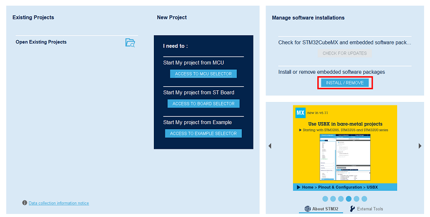
Open STM32CubeMX, in the software pack area, click on the install/remove button.
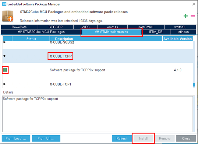
Then select the STMicroelectronics tab, scroll down to the X-Cube-TCPP software pack, and click on the install button if it is not already installed.
2. Creating the project
5min
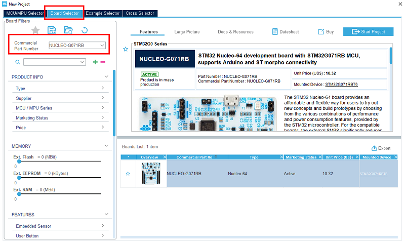
In STM32CubeMX, create a new STM32 project. As a target selection, choose the NUCLEO-G071RB from the Board Selector Tab.
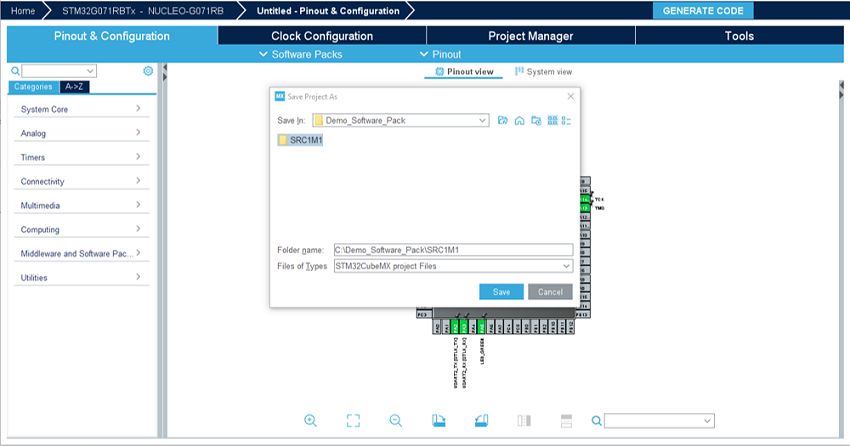
Click Start Project, then in the file menu, create a new folder under your project's name, and click Save.
When prompted for initializing peripherals with their default mode, click No.
3. Configuring the system
At this point, your project is created. The next steps focus on the configuration of the peripherals and options needed for the project.
3.1. Clear the pinout
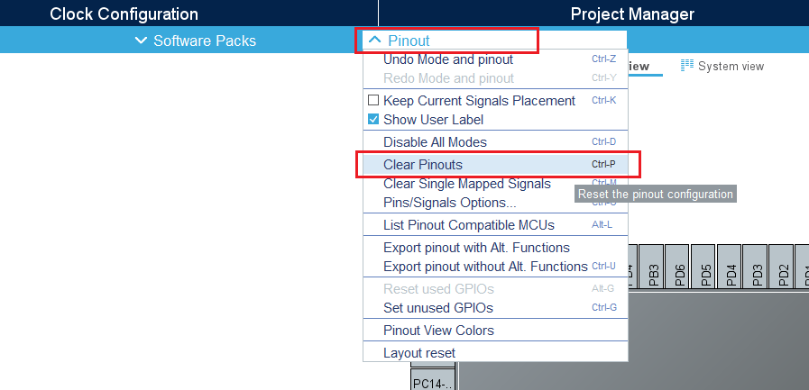
To start from a blank configuration, click on the Pinout menu and select Clear Pinouts. This resets the pinouts in the Pinout view.
3.2. Select the X-Cube-TCPP software pack
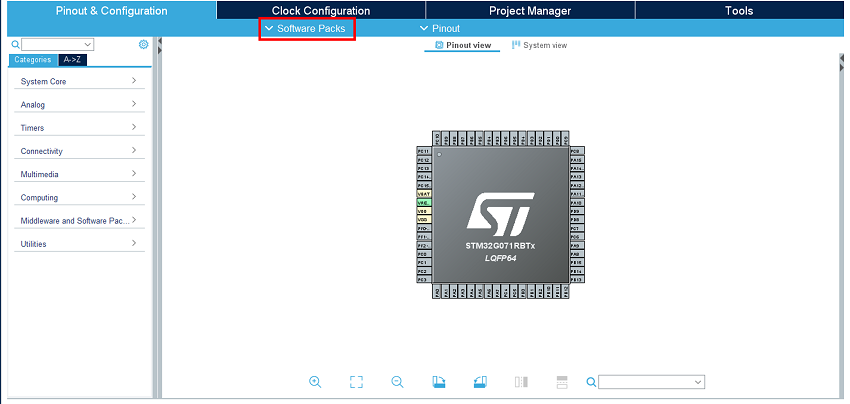
From the software pack menu:
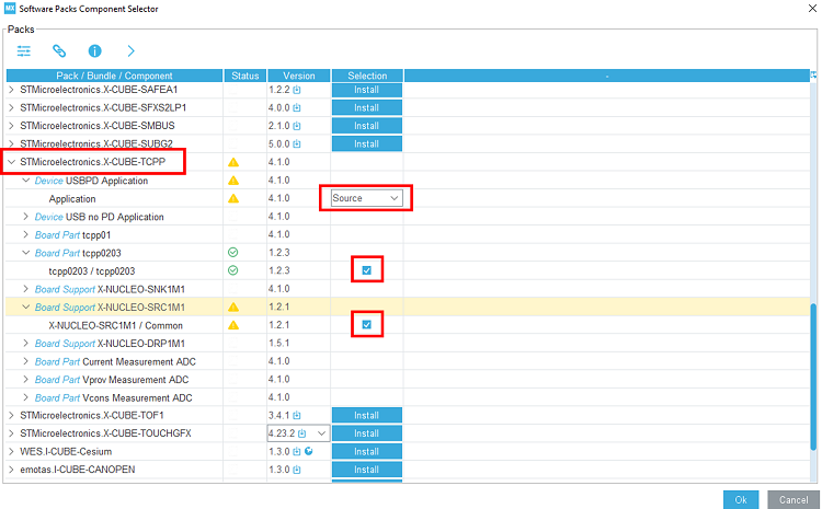
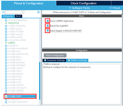
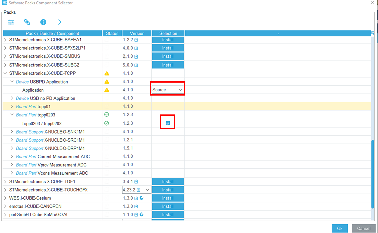
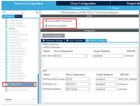
Select the X-CUBE-TCPP software pack and enable its Source application, the tcpp0203 board part, and the X-NUCLEO-SRC1M1 board support.
3.3. Configure UCPD peripheral
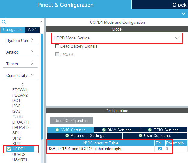
In the Connectivity tab, select the UCPD1 peripheral and enable it in source mode. Under the NVIC Settings tab, enable UCPD global interrupts.
Under the DMA Settings tab, add UCPD1_RX and UCPD1_TX DMA requests. Select DMA1 channel 4 for RX and DMA1 channel 2 for TX.
3.4. Configure FreeRTOS Middleware
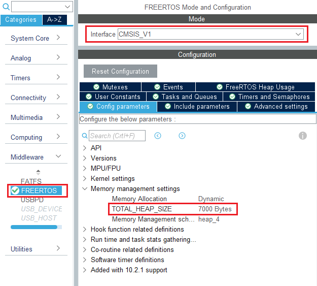
In the Middleware section, enable FreeRTOS with CMSIS_V1 interface. Under the Config Parameters tab, change "TOTAL_HEAP_SIZE" to 7000 bytes.
3.5. Configure USBPD Middleware
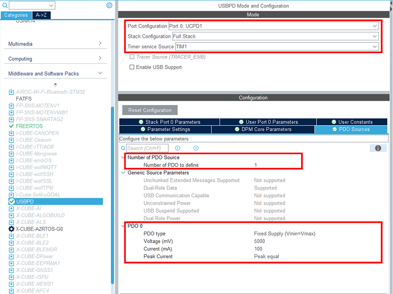
In the Middleware section, enable USBPD with the following configuration:
- Port configuration: Port 0: UCPD1
- Stack configuration: PD3 Full Stack
- Timer service source: TIM1
Under the PDO Source tab, verify the following configuration:
- Number of Source PDOs for port 0: 1
- Port 0 Source PDO 0 : 5V 100mA
3.6. Configure ADC peripheral
For the Power Delivery stack to work, VBUS needs to be monitored. To do it, an ADC needs to be configured to measure the VBUS voltage and current.
Since the X-NUCLEO-SRC1M1 BSP is used, the ADC configuration does not need to be done in CubeMX.
As the ADC HAL drivers are required for it to work properly, the ADC needs to be configured in CubeMX for it to include the driver files, but the actual configuration and init function are not called in this project.
In the Analog section, enable ADC1 peripheral channel 0. Leave the configuration as default, as the software pack reconfigures it.
3.7. Configure I2C peripheral
As the X-NUCLEO-SRC1M1 shield includes a TCPP02-M18 that communicates through I2C, the I2C peripheral needs to be enabled in this project.
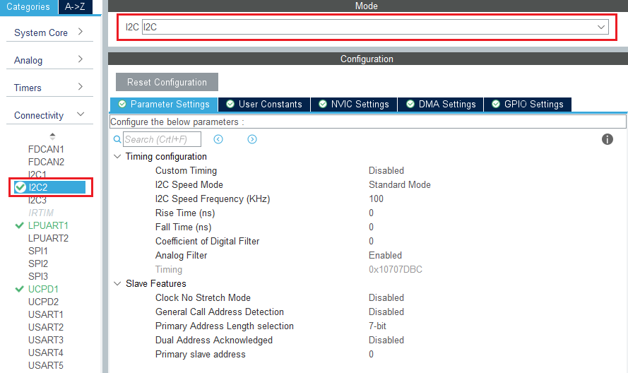
In the Connectivity section, enable I2C2 peripheral in I2C mode. Leave the configuration as default, as the software pack reconfigures it.
Note: Enable the I2C2 peripheral in the CubeMX view for code generation to include the I2C drivers as done for the ADC.
3.8. Enable the software pack
In the middleware and software pack category, select the X-Cube-TCPP software pack. Enable the 'Source' application, the 'tcpp0203' board part, and the 'X-NUCLEO-SRC1M1' board support.
3.9. Configure Clocks
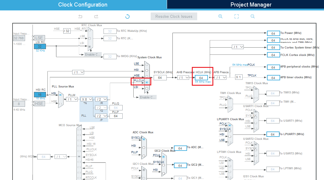
Under the Clock Configuration main tab, change system clock mux to PLLCLK. It sets HCLK clock to 64 MHz.
3.10. [OPTIONAL] Configure Tracer for debug
3.10.1. Configure LPUART
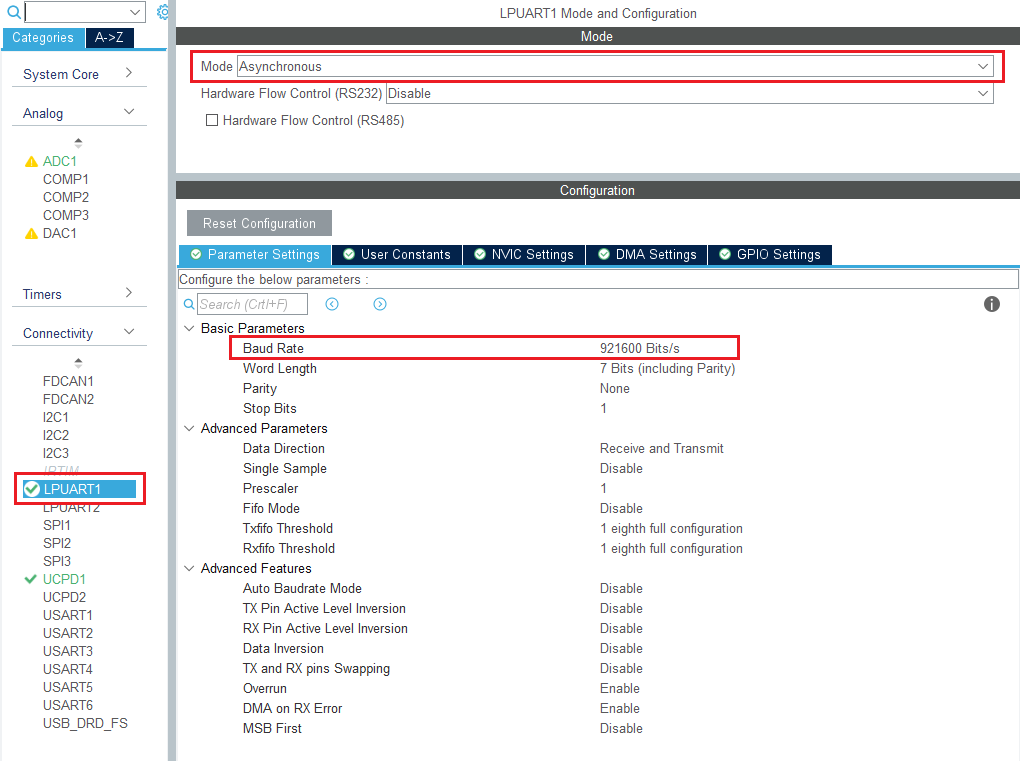
On the STM32G0 Nucleo-64 board, the Virtual COM port connected to the ST-LINK is the LPUART1.
In the Connectivity section, enable LPUART1 in asynchronous mode, and baudrate 921600 bauds. Leave the rest as default.
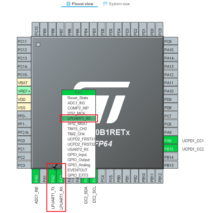
In the pinout view, left-click PA2 and PA3 to remap them to LPUART1_TX and LPUART1_RX.
Under the DMA Configuration tab, add a request for LPUART1_TX. Use DMA1 channel 3.
Finally, under the NVIC Settings tab, enable LPUART1 global interrupts.
3.10.2. Configure embedded tracer
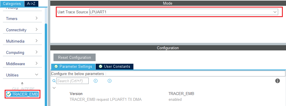
In the Utilities section, select TRACER_EMB and use LPUART1 as the trace source.
Then, go back to the USBPD middleware configuration and check the Tracer Source checkbox.
3.10.3. Configure UCPD monitor firmware responder for debug
The firmware interactive stack responder can be activated if interaction with the USB-PD stack is needed, using the UCPD monitor tool STM32CubeMonUCPD. In the Utilities section, enable GUI_INTERFACE, then enter free text to describe the board.
4. Configure the project
5min
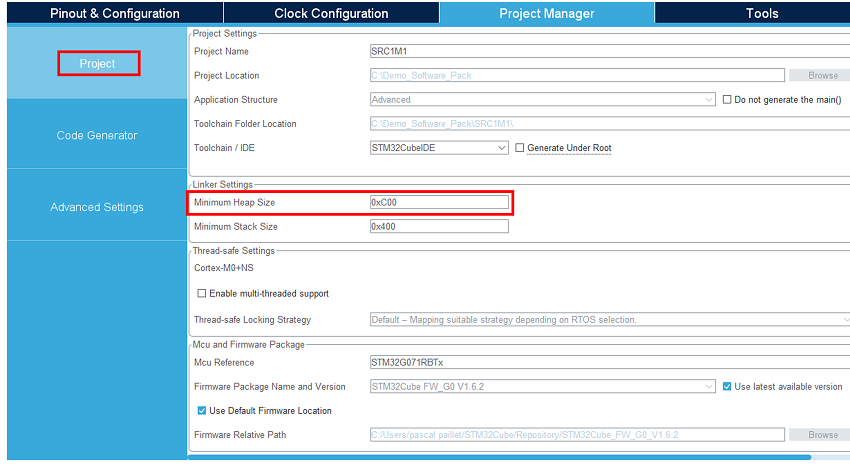
Under the Project Manager main tab, configure the minimum stack size to 0xC00 under the Project tab. This is a first value, which can be tuned later, depending on application needs.
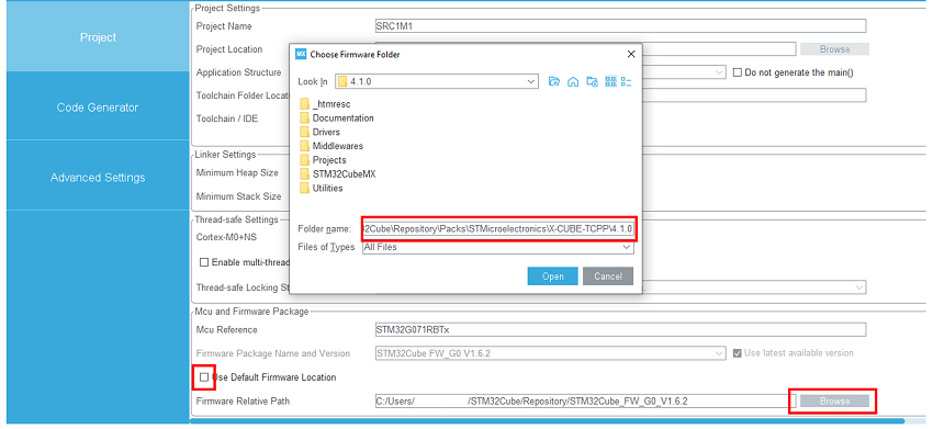
For STM32G0 or G4 MCU, uncheck “Use default firmware location” and instead, select the software pack “c:|\user\ … \STM32Cube\Repositoryctronics/Packs\STMicroelectronics\X-CUBE-TCPP\V4.1.0\” as firmware location to be sure to use the latest USBPD lib releases as the standard evolution is very fast.
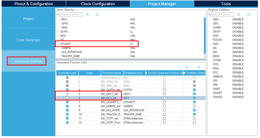
Under the Advanced Settings tab, change the LPUART driver to LL to save a bit of memory heap size. As ADC and I2C initialization functions are not needed (handled by the BSP drivers), uncheck Generate Code for the MX_I2C_Init and MX_ADC1_Init functions.
5. Generate the code
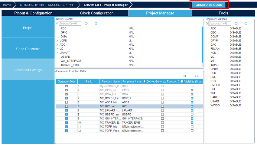
Save your file with Ctrl+s and select generate code.
A warning appears, informing that a proper HAL timebase is not defined. It is safer to use a dedicated timer as a HAL timebase source.
For this demonstration, the below warning can be ignored by clicking Yes.
STM32CubeIDE starts and imports the project.
This project contains the following folders:
- The USBPD folder contains the source files that are needed to edit to enrich the Power Delivery application.
- The Core folder contains the source files for the core of the project.
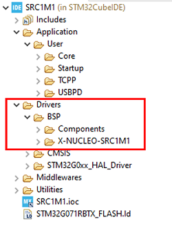
- The Drivers folder contains the HAL drivers for the STM32, and the BSP for the Nucleo board, and X-NUCLEO-SRC1M1 shield.
- The Middleware folder contains the source files and the libraries for FreeRTOS™ and USB-PD.
- The Utilities folder contains the GUI (UCPD monitor) and tracer embedded source files part.
The Drivers folder in the Explorer view of the project must contain the BSP folders added earlier.
6. Configure the shield's jumpers
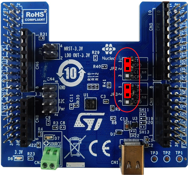
Place the jumpers on the X-NUCLEO-SRC1M1 shield as shown in the picture.
Next, plug an external 5V source into the green "source" connector.
With this configuration, the board is powered by the ST-Link of the Nucleo board.
To power your system from the external power supply connected to the "source" terminal, and not from the ST-Link, add the JP1 jumpers between 1-2 and 3-4.
7. Compile and run the application
The compilation must be performed without error or warnings.
Build the application by clicking on the button (or select Project/Build Project).
Run the application by clicking on the button (or select Run/Run)
8. Establish the first explicit contract
5min
With your application running on the board, launch the STM32CubeMonitor-UCPD application.
The user's board must appear in the list when clicking "Refresh list of connected boards", so double click on the
corresponding line (or click "NEXT").
Note: The ComPort may be different. It depends on the number of boards installed on the computer. Double click on the desired UCPD port, here Port 0, or select it and click "NEXT".
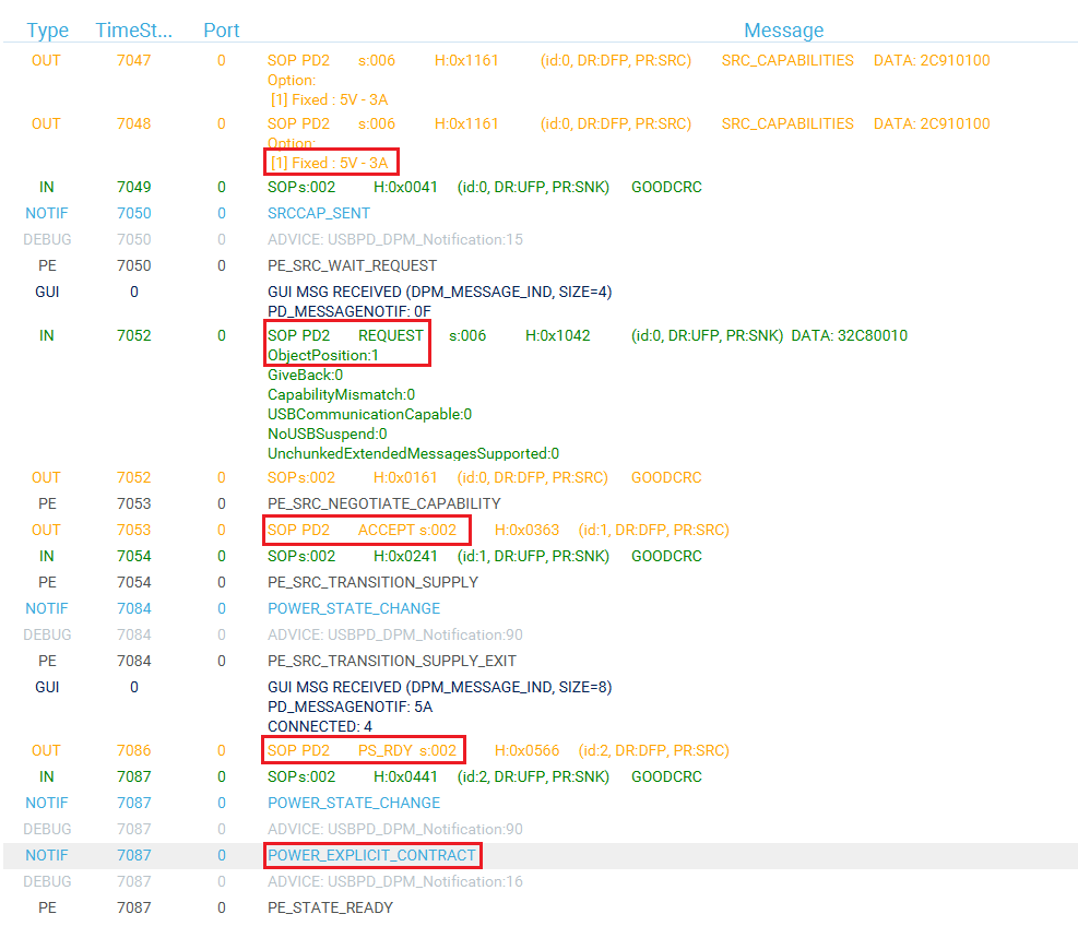
Click on the TRACES button in the bottom right corner to get protocol traces. You can then plug a power delivery sink into the USB Type-C® receptacle of the X-NUCLEO-SRC1M1 shield. The screen may look like this:
The figure above shows the communication between the STM32G0 and the power delivery sink on the right panel. It is possible to verify the correct sequence to reach an explicit contract:
- The capabilities are sent by the STM32G0 source (OUT orange message).
- The request is sent by the sink (IN green message).
- The ACCEPT and the PS_RDY are sent by the STM32G0 source (OUT orange message).
- The contract negotiation ends by the POWER_EXPLICIT_CONTRACT notification (blue message).
For more details on how to use this tool, refer to UM2468. And for more details on the protocol, refer to UM2552. Note that this trace is very helpful for debugging and application development.
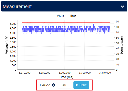
You can also use the Measurement window in STM32CubeMonitor-UCPD to display a graph of the measured VBUS voltage and delivered current. Set the sampling period and click start.
You can find other applicative examples on GitHub: x-cube-tcpp
9. Information focus : Code inserted by the software pack
By enabling the software pack in section 3.8, the code below has been added automatically in following files:
usbpd_dpm_user_h |
Between the /* USER CODE BEGIN-END Typedef */ tags:
#if !defined(USBPD_REV_MAJOR)
#define USBPD_REV_MAJOR (3U) /* USBPD Specification revision major */
#define USBPD_REV_MINOR (1U) /* USBPD Specification revision minor */
#define USBPD_VERSION_MAJOR (1U) /* USBPD Specification version major */
#define USBPD_VERSION_MINOR (7U) /* USBPD Specification version minor */
#endif /* !USBPD_REV_MAJOR */
/**
* @brief USBPD DPM handle Structure definition
* @{
*/
typedef struct
{
uint32_t DPM_ListOfRcvSNKPDO[USBPD_MAX_NB_PDO]; /*!< The list of received Sink Power Data Objects from Port partner (when Port partner is a Sink or a DRP port). */
uint32_t DPM_NumberOfRcvSNKPDO; /*!< The number of received Sink Power Data Objects from port Partner (when Port partner is a Sink or a DRP port). */
uint32_t DPM_ListOfRcvSRCPDO[USBPD_MAX_NB_PDO]; /*!< The list of received Source Power Data Objects from Port partner */
uint32_t DPM_NumberOfRcvSRCPDO; /*!< The number of received Source Power Data Objects from port Partner (when Port partner is a Source or a DRP port). */
uint32_t DPM_RcvRequestDOMsg; /*!< Received request Power Data Object message from the port Partner */
uint32_t DPM_RequestDOMsgPrevious; /*!< Previous Request Power Data Object message to be sent */
USBPD_PPSSDB_TypeDef DPM_RcvPPSStatus; /*!< PPS Status received by port partner */
USBPD_SKEDB_TypeDef DPM_RcvSNKExtendedCapa; /*!< SNK Extended Capability received by port partner */
uint32_t DPM_RequestDOMsg; /*!< Request Power Data Object message to be sent */
uint32_t DPM_RDOPosition; /*!< RDO Position of requested DO in Source list of capabilities */
uint32_t DPM_RDOPositionPrevious; /*!< RDO Position of previous requested DO in Source list of capabilities */
uint32_t DPM_RequestedVoltage; /*!< Value of requested voltage */
uint32_t DPM_RequestedCurrent; /*!< Value of requested current */
} USBPD_HandleTypeDef;
Between the /* USER CODE BEGIN-END Variables */ tags: extern USBPD_HandleTypeDef DPM_Ports[USBPD_PORT_COUNT];
|
usbpd_dpm_user_c |
Between the /* USER CODE BEGIN-END Includes */ tags:
#if !defined(_TRACE)
#include "string.h"
#endif /* !_TRACE */
Between the /* USER CODE BEGIN-END Variables */ tags: USBPD_HandleTypeDef DPM_Ports[USBPD_PORT_COUNT];
Between the /* USER CODE BEGIN-END Prototypes */ tags: static USBPD_StatusTypeDef DPM_TurnOnPower(uint8_t PortNum, USBPD_PortPowerRole_TypeDef Role);
static USBPD_StatusTypeDef DPM_TurnOffPower(uint8_t PortNum, USBPD_PortPowerRole_TypeDef Role);
Between the /* USER CODE BEGIN-END USBPD_DPM_UserInit */ tags: /* PWR SET UP */
if(USBPD_OK != USBPD_PWR_IF_Init())
{
return USBPD_ERROR;
}
Between the /* USER CODE BEGIN-END USBPD_DPM_UserCableDetection */ tags: #ifdef _GUI_INTERFACE
switch(State)
{
case USBPD_CAD_EVENT_ATTEMC:
case USBPD_CAD_EVENT_ATTACHED:
/* Format and send a notification to GUI if enabled */
if (NULL != DPM_GUI_FormatAndSendNotification)
{
DPM_GUI_FormatAndSendNotification(PortNum, DPM_GUI_NOTIF_ISCONNECTED, 0);
}
break;
default :
/* Format and send a notification to GUI if enabled */
if (NULL != DPM_GUI_FormatAndSendNotification)
{
DPM_GUI_FormatAndSendNotification(PortNum, DPM_GUI_NOTIF_ISCONNECTED | DPM_GUI_NOTIF_POWER_EVENT, 0);
}
}
#endif /*_GUI_INTERFACE*/
switch(State)
{
case USBPD_CAD_EVENT_ATTACHED:
case USBPD_CAD_EVENT_ATTEMC:
{
if (DPM_Params[PortNum].PE_PowerRole == USBPD_PORTPOWERROLE_SRC)
{
if (USBPD_OK != USBPD_PWR_IF_VBUSEnable(PortNum))
{
/* Should not occur */
NVIC_SystemReset();
}
}
break;
}
case USBPD_CAD_EVENT_DETACHED :
case USBPD_CAD_EVENT_EMC :
default :
if (DPM_Params[PortNum].PE_PowerRole == USBPD_PORTPOWERROLE_SRC)
{
if (USBPD_OK != USBPD_PWR_IF_VBUSDisable(PortNum))
{
/* Should not occur */
while(1);
}
}
break;
}
Between the /* USER CODE BEGIN-END USBPD_DPM_HardReset */ tags: switch (Status)
{
case USBPD_HR_STATUS_WAIT_VBUS_VSAFE0V:
if (USBPD_PORTPOWERROLE_SRC == CurrentRole)
{
/* Reset the power supply */
DPM_TurnOffPower(PortNum, USBPD_PORTPOWERROLE_SRC);
}
break;
case USBPD_HR_STATUS_WAIT_VBUS_VSAFE5V:
if (CurrentRole == USBPD_PORTPOWERROLE_SRC)
{
/* Power on the power supply */
DPM_TurnOnPower(PortNum, CurrentRole);
}
break;
default:
break;
}
Between the /* USER CODE BEGIN-END USBPD_DPM_GetDataInfo */ tags: /* Case Requested voltage value Data information */
case USBPD_CORE_DATATYPE_REQ_VOLTAGE :
*Size = 4;
(void)memcpy((uint8_t*)Ptr, (uint8_t *)&DPM_Ports[PortNum].DPM_RequestedVoltage, *Size);
break;
case USBPD_CORE_DATATYPE_SRC_PDO :
USBPD_PWR_IF_GetPortPDOs(PortNum, DataId, Ptr, Size);
*Size *= 4;
break;
case USBPD_CORE_REVISION:
{
*Size = sizeof(USBPD_RevisionDO_TypeDef);
USBPD_RevisionDO_TypeDef rev =
{
/* Hardcoded values, user should use a global USBPD_RevisionDO_TypeDef variable */
.b.Revision_major = USBPD_REV_MAJOR, /*!< Major revision */
.b.Revision_minor = USBPD_REV_MINOR, /*!< Minor revision */
.b.Version_major = USBPD_VERSION_MAJOR, /*!< Major version */
.b.Version_minor = USBPD_VERSION_MINOR /*!< Minor version */
};
memcpy((uint8_t *)Ptr, &rev, *Size);
break;
}
default:
break;
Between the /* USER CODE BEGIN-END USBPD_DPM_SetDataInfo */ tags: /* Case Received Request PDO Data information : */
case USBPD_CORE_DATATYPE_RDO_POSITION :
if (Size == 4)
{
uint8_t* temp;
temp = (uint8_t*)&DPM_Ports[PortNum].DPM_RDOPosition;
(void)memcpy(temp, Ptr, Size);
DPM_Ports[PortNum].DPM_RDOPositionPrevious = *Ptr;
temp = (uint8_t*)&DPM_Ports[PortNum].DPM_RDOPositionPrevious;
(void)memcpy(temp, Ptr, Size);
}
break;
/* Case Received Sink PDO values Data information :*/
case USBPD_CORE_DATATYPE_RCV_SNK_PDO :
if (Size <= (USBPD_MAX_NB_PDO * 4))
{
uint8_t* rdo;
DPM_Ports[PortNum].DPM_NumberOfRcvSNKPDO = (Size / 4);
/* Copy PDO data in DPM Handle field */
for (uint32_t index = 0; index < (Size / 4); index++)
{
rdo = (uint8_t*)&DPM_Ports[PortNum].DPM_ListOfRcvSNKPDO[index];
(void)memcpy(rdo, (Ptr + (index * 4u)), (4u * sizeof(uint8_t)));
}
}
break;
case USBPD_CORE_DATATYPE_RCV_REQ_PDO : /*!< Storage of Received Sink Request PDO value */
if (Size == 4)
{
memcpy((uint8_t *)&DPM_Ports[PortNum].DPM_RcvRequestDOMsg, Ptr, 4);
}
break;
case USBPD_CORE_REVISION:
{
/* Does nothing: User have to implement a global revision variable */
USBPD_RevisionDO_TypeDef rev = {0};
memcpy((uint8_t *)&rev, Ptr, sizeof(USBPD_RevisionDO_TypeDef));
break;
}
default:
break;
Between the /* USER CODE BEGIN-END USBPD_DPM_EvaluateRequest */ tags: USBPD_StatusTypeDef _retr = USBPD_REJECT;
USBPD_PDO_TypeDef pdo;
USBPD_SNKRDO_TypeDef rdo;
/* read the request value received */
rdo.d32 = DPM_Ports[PortNum].DPM_RcvRequestDOMsg;
/* Search PDO in Port Source PDO list, that corresponds to Position provided in Request RDO */
if (USBPD_PWR_IF_SearchRequestedPDO(PortNum, rdo.GenericRDO.ObjectPosition, &pdo.d32) == USBPD_OK)
{
/* Evaluate the request */
if(pdo.GenericPDO.PowerObject == USBPD_CORE_PDO_TYPE_FIXED)
{
if((rdo.FixedVariableRDO.OperatingCurrentIn10mAunits > pdo.SRCFixedPDO.MaxCurrentIn10mAunits)
|| ((rdo.FixedVariableRDO.MaxOperatingCurrent10mAunits > pdo.SRCFixedPDO.MaxCurrentIn10mAunits)&&(rdo.FixedVariableRDO.CapabilityMismatch==0)))
{
/* Sink requests too much maximum operating current */
/* USBPD_DPM_EvaluateRequest: Sink requests too much maximum operating current */
_retr = USBPD_REJECT;
}
else
{
/* Save the power object */
*PtrPowerObject = pdo.GenericPDO.PowerObject;
/* Set RDO position and requested voltage in DPM port structure */
DPM_Ports[PortNum].DPM_RequestedVoltage = pdo.SRCFixedPDO.VoltageIn50mVunits * 50;
DPM_Ports[PortNum].DPM_RDOPositionPrevious = DPM_Ports[PortNum].DPM_RDOPosition;
DPM_Ports[PortNum].DPM_RDOPosition = rdo.GenericRDO.ObjectPosition;
_retr = USBPD_ACCEPT;
}
}
}
return _retr;
Between the /* USER CODE BEGIN-END USBPD_USER_PRIVATE_FUNCTIONS */ tags: /**
* @brief Turn Off power supply.
* @param PortNum The current port number
* @param Role Port power role
* @retval USBPD_OK, USBPD_ERROR
*/
static USBPD_StatusTypeDef DPM_TurnOffPower(uint8_t PortNum, USBPD_PortPowerRole_TypeDef Role)
{
USBPD_StatusTypeDef status;
status = USBPD_PWR_IF_VBUSDisable(PortNum);
return status;
}
/**
* @brief Turn On power supply.
* @param PortNum The current port number
* @param Role Port power role
* @retval USBPD_ACCEPT, USBPD_WAIT, USBPD_REJECT
*/
static USBPD_StatusTypeDef DPM_TurnOnPower(uint8_t PortNum, USBPD_PortPowerRole_TypeDef Role)
{
USBPD_StatusTypeDef status;
/* Enable the output */
status = USBPD_PWR_IF_VBUSEnable(PortNum);
return status;
}
|
usbpd_pdo_defs.h |
Between the /* USER CODE BEGIN-END Typedef */ tags:
/**
* @brief USBPD Port PDO Structure definition
*/
typedef struct
{
uint32_t *ListOfPDO; /*!< Pointer on Power Data Objects list, defining port capabilities */
uint8_t *NumberOfPDO; /*!< Number of Power Data Objects defined in ListOfPDO
This parameter must be set at max to @ref USBPD_MAX_NB_PDO value */
} USBPD_PortPDO_TypeDef;
/**
* @brief USBPD Port PDO Storage Structure definition
*/
typedef struct
{
USBPD_PortPDO_TypeDef SourcePDO; /*!< SRC Power Data Objects */
USBPD_PortPDO_TypeDef SinkPDO; /*!< SNK Power Data Objects */
} USBPD_PWR_Port_PDO_Storage_TypeDef;
Between the /* USER CODE BEGIN-END Variables */ tags: #ifndef _GUI_INTERFACE
#ifndef __USBPD_PWR_IF_C
extern uint8_t USBPD_NbPDO[4];
extern uint32_t PORT0_PDO_ListSRC[USBPD_MAX_NB_PDO];
extern uint32_t PORT0_PDO_ListSNK[USBPD_MAX_NB_PDO];
#else /* __USBPD_PWR_IF_C */
uint8_t USBPD_NbPDO[4] = {(PORT0_NB_SINKPDO),
(PORT0_NB_SOURCEPDO)};
#endif /* __USBPD_PWR_IF_C */
#endif /* _GUI_INTERFACE */
|
usbpd_pwr_if.c |
Between the /* USER CODE BEGIN-END Private_Variables */ tags:
/**
* @brief USBPD Port PDO Storage array declaration
*/
USBPD_PWR_Port_PDO_Storage_TypeDef PWR_Port_PDO_Storage[USBPD_PORT_COUNT];
Between the /* USER CODE BEGIN-END USBPD_PWR_IF_Init */ tags: USBPD_StatusTypeDef _status = USBPD_OK;
/* Set links to PDO values and number for Port 0 (defined in PDO arrays in H file). */
PWR_Port_PDO_Storage[USBPD_PORT_0].SourcePDO.ListOfPDO = (uint32_t *) PORT0_PDO_ListSRC;
PWR_Port_PDO_Storage[USBPD_PORT_0].SourcePDO.NumberOfPDO = &USBPD_NbPDO[1];
return _status;
Between the /* USER CODE BEGIN-END USBPD_PWR_IF_SetProfile */ tags: USBPD_PDO_TypeDef _pdo;
USBPD_SNKRDO_TypeDef _rdo;
_rdo.d32 = DPM_Ports[PortNum].DPM_RcvRequestDOMsg;
_pdo.d32 = PORT0_PDO_ListSRC[0];
return (BSP_ERROR_NONE == BSP_USBPD_PWR_VBUSSetVoltage_Fixed(PortNum,
_pdo.SRCFixedPDO.VoltageIn50mVunits * 50,
(_rdo.FixedVariableRDO.OperatingCurrentIn10mAunits * 10),
(_rdo.FixedVariableRDO.MaxOperatingCurrent10mAunits * 10)
)? USBPD_OK : USBPD_ERROR);
Between the /* USER CODE BEGIN-END USBPD_PWR_IF_GetPortPDOs */ tags: if (DataId == USBPD_CORE_DATATYPE_SRC_PDO)
{
#if defined (_GUI_INTERFACE)
*Size = USBPD_NbPDO[1];
memcpy(Ptr,PORT0_PDO_ListSRC, sizeof(uint32_t) * USBPD_NbPDO[1]);
#else
*Size = PORT0_NB_SOURCEPDO;
memcpy(Ptr,PORT0_PDO_ListSRC, sizeof(uint32_t) * PORT0_NB_SOURCEPDO);
#endif /* _GUI_INTERFACE */
}
else
{
#if defined (_GUI_INTERFACE)
*Size = USBPD_NbPDO[0];
memcpy(Ptr,PORT0_PDO_ListSNK, sizeof(uint32_t) * USBPD_NbPDO[0]);
#else
*Size = PORT0_NB_SINKPDO;
memcpy(Ptr,PORT0_PDO_ListSNK, sizeof(uint32_t) * PORT0_NB_SINKPDO);
#endif /* _GUI_INTERFACE */
}
uint32_t nbpdo, index, nb_valid_pdo = 0;
uint32_t *ptpdoarray = NULL;
USBPD_PDO_TypeDef pdo_first;
USBPD_PDO_TypeDef pdo;
/* Check if valid port */
if (USBPD_PORT_IsValid(PortNum))
{
/* According to type of PDO to be read, set pointer on values and nb of elements */
switch (DataId)
{
case USBPD_CORE_DATATYPE_SRC_PDO :
nbpdo = *PWR_Port_PDO_Storage[PortNum].SourcePDO.NumberOfPDO;
ptpdoarray = PWR_Port_PDO_Storage[PortNum].SourcePDO.ListOfPDO;
/* Save the 1st PDO */
pdo_first.d32 = *ptpdoarray;
/* Reset unchunked bit if current revision is PD2.0*/
if (USBPD_SPECIFICATION_REV2 == DPM_Params[PortNum].PE_SpecRevision)
{
pdo_first.SRCFixedPDO.UnchunkedExtendedMessage = USBPD_PDO_SRC_FIXED_UNCHUNK_NOT_SUPPORTED;
}
break;
default:
nbpdo = 0;
break;
}
/* Copy PDO data in output buffer */
for (index = 0; index < nbpdo; index++)
{
pdo.d32 = *ptpdoarray;
/* Copy only PDO (and not APDO in case of current revision is PD2.0) */
if ((USBPD_SPECIFICATION_REV2 == DPM_Params[PortNum].PE_SpecRevision)
&& (pdo.GenericPDO.PowerObject == USBPD_CORE_PDO_TYPE_APDO))
{
}
else
{
/* Copy 1st PDO as potentially FRS or UNCHUNKED bits have been reset */
if (0 == index)
{
(void)memcpy(Ptr, (uint8_t*)&pdo_first.d32, 4u);
}
else
{
(void)memcpy((Ptr + (nb_valid_pdo * 4u)), (uint8_t*)ptpdoarray, 4u);
}
nb_valid_pdo++;
}
ptpdoarray++;
}
/* Set nb of read PDO (nb of u32 elements); */
*Size = nb_valid_pdo;
}
Between the /* USER CODE BEGIN-END USBPD_PWR_IF_SearchRequestedPDO */ tags: if((RdoPosition == 0) || (RdoPosition > *PWR_Port_PDO_Storage[PortNum].SourcePDO.NumberOfPDO))
{
/* Invalid PDO index */
return USBPD_FAIL;
}
*Pdo = PWR_Port_PDO_Storage[PortNum].SourcePDO.ListOfPDO[RdoPosition - 1];
return USBPD_OK;
|
10. Project with a custom board
This chapter allows building an USBPD source application using a custom board with an STM32 MCU from series G0, G4, H5, L5, or U5 that includes the UCPD peripheral.
- As in chapter 2: Create the project
- As in chapter 3.1: Clear the pinout
- As in chapter 3.2: Select the X-CUBE-TCPP software pack
Do not select the board support for X-NUCLEO-SRC1M1 as your application is based on a custom board.
- As in chapter 3.3: Configure UCPD Peripheral
- As in chapter 3.4: Configure FreeRTOS Middleware
- As in chapter 3.5: Configure USBPD Middleware
- Configure ADC peripheral
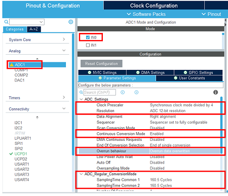
Select and configure the ADC and its channel on which Vbus is connected for monitoring. Select the ADC and its channel. Adjust the clock prescaler. Keep 12 Bits resolution. Enable the continuous conversion mode, and set a medium cycle sampling time.
- Configure I2C Peripheral
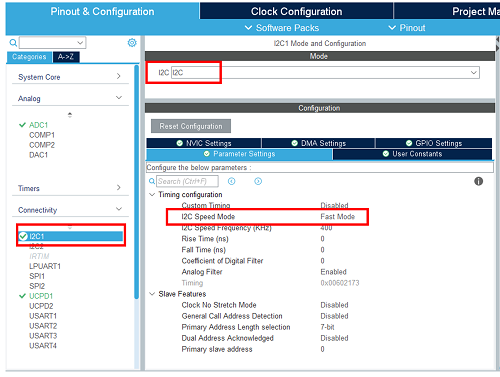
Enable the I2C connected to the TCPP02 I2C bus. Set its speed in fast Mode.
- Configure GPIO
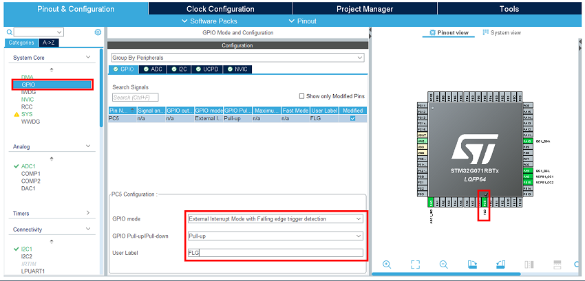
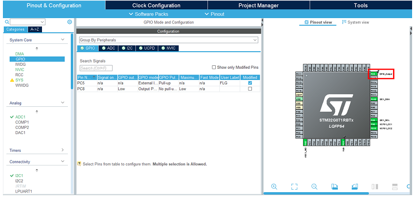
Enable and configure the external interrupt input where the TCPP02 FLG signal is connected. Select it in the pinout view. In the GPIO category, set it as external interrupt mode with falling edge trigger detection. Enable its Pull-up.
In the Pinout view, select the GPIO Output for TCPP02 Enable.
- Enable the software Pack
In the middleware category, select the X-Cube-TCPP Software pack and enable its application and board part.
- Assign resources to the application requirements.
- As in chapter 4: Configure the project
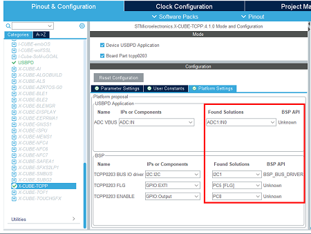
However, in the advanced settings, keep ADC and I2C initialization code generation.
- As in chapter 5: Generate the code
- As in chapter 7: Compile and run the application
11. References