1. What is NanoEdge AI Library for anomaly detection?
NanoEdge™ AI Library is an Artificial Intelligence (AI) static library originally developed by Cartesiam, for embedded C software running on Arm® Cortex® microcontrollers.
When embedded on microcontrollers, it gives them the ability to easily "learn" and "understand" sensor patterns, by themselves, without the need for the user to have additional skills in Mathematics, Machine Learning, or data science.
The NanoEdge AI static library for anomaly detection is the code that contains an AI model (for example, as a bundle of signal treatment, Machine Learning model, and optimally tuned hyperparameters). It is designed to gather knowledge incrementally during a learning phase to become able to detect potential anomalous machine behaviors, and possibly predict them.
2. What is the intelligent sensor processing unit (ISPU)?
The ISPU (intelligent sensor processing unit) is an embedded programmable core that allows reading sensor data and processing it inside the ISM330ISN device and can directly provide, when necessary, the results of said processing to an external microcontroller. The ISPU can run any type of processing, from basic signal processing to AI algorithms. NanoEdge AI Studio provides ready-to-use anomaly detection binary for the ISPU.
3. How does it work?
As described above, NanoEdge AI Library is designed to detect anomalies from a signal. It runs continuously in the ISPU as it is an always-on device. A learning phase in needed to learn the nominal behavior of the device monitored. This phase can be started and stopped by sending commands from the main MCU to the ISPU. This learning phase creates the knowledge of the NanoEdge AI Library. Considering that the ISPU does not have any on-board non-volatile memory, the knowledge is lost each time the device is powered down.
Once the learning phase is done, the ISPU can be set in detection mode. The monitoring is done continuously. Each time a signal is detected as abnormal, the ISPU raises an interruption. If opted for, the ISPU can send the raw data of the corresponding signal.
4. Getting Started
4.1. NanoEdgeAI Studio with the ISPU
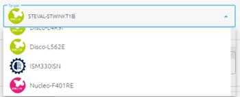
In NanoEdge Studio, select the ISM330ISN in the target list.
Once a benchmark is complete, the Deployment section is enabled. Select the corresponding benchmark, and the datarate/fullscale settings as shown below.
After clicking Compile and selecting the library type, a .zip file is downloaded to the computer.
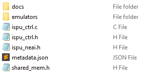
It contains:
- the NanoEdge AI ISPU binary
ispu_neai.h
This file contains the complete binary. It must not be modified. It declares an array used in the initialization phase to load the binary in the ISPU's memory.
- the ISPU control source file
ispu_ctrl.c - the ISPU control header file
ispu_ctrl.h - the shared memory file
shared_mem.h
Those files are used to control the ISPU. It includes all the functions needed for initialization, for sending commands, processing the outputs, and so on.
- the NanoEdge AI Emulators (both Windows® and Linux® versions)
- the configuration file ispu_neai.ucf that can be used with Unico GUI software to configure the ISPU.
- some library metadata information in
metadata.json
4.2. MCU configurations
4.2.1. I²C/SPI
The ISPU can be connected via I²C or SPI. In both cases, to simplify the use of theispu_ctrl library, ispu_write and ispu_read must be filled with the I²C or SPI read and write functions depending on the library used.
void ispu_read(uint8_t reg, uint8_t *val, uint16_t len)
{
	/* USER BEGIN */

	/* USER END */
}

void ispu_write(uint8_t reg, uint8_t val)
{
	/* USER BEGIN */

	/* USER END */
}
4.2.2. Interruptions
The ISPU uses two GPIOs to raise interruptions. Using these interruptions, it is possible to put the main MCU in a sleep mode and only be wake it if an anomaly happens. Both GPIOs must be configured in rising edge only, no pull.
  GPIO_InitStruct.Pin = INT2_Pin;
  GPIO_InitStruct.Mode = GPIO_MODE_IT_RISING;
  GPIO_InitStruct.Pull = GPIO_NOPULL;
  HAL_GPIO_Init(INT2_GPIO_Port, &GPIO_InitStruct);
4.2.3. Communication protocol
Communication is based on:
- Shared memory with write access for the MCU and read access for the ISPU
- An interruption line controlled by the ISPU to the MCU
The MCU controls the communication protocol. To send a command, it writes a command and its arguments into the shared memory. Then, the ISPU detects a new command. The MCU fetches the interruption, gets the status of the command execution, and if needed, sends the next command.
5. Developing an always-on monitoring device
5.1. Load the device
As mentioned above, the ISPU does not have on-board non-volatile memory. The ispu_neai.h contains an array with all the register values that have to be sent though the I²C/SPI.
	for (uint32_t i = 0; i < sizeof(ispu_conf) / sizeof(ucf_line_t_neai); i++) {
		if (ispu_conf[i].op == MEMS_UCF_OP_WRITE)
			ispu_write(ispu_conf[i].address, ispu_conf[i].data);
		else if (ispu_conf[i].op == MEMS_UCF_OP_DELAY)
			HAL_Delay(ispu_conf[i].data);
	}
5.2. Learning mode
The NanoEdge AI Library in anomaly detection needs a learning phase. This learning, happening in the ISPU, creates the knowledge of the library. All the signals learned are then considered as nominal by definition. The learning mode can be set at any time to run additional learning iterations an add new nominal signals to the knowledge. The ISPU does not have on-board non-volatile memory, hence, the knowledge is lost each each time the ISPU is powered down.
In learning mode, the ISPU gets new data from the accelerometer and updates the knowledge, until another mode is turned on. INT2 is raised each time a signal has been learned. It helps to count the number of learning iterations done. However, the most important is to create a complete learning with all the nominal regimes. The whole range of nominal behaviors for the target application must be learned.
5.3. Detection mode
In detection mode, the ISPU monitors continuously.
- Detect Mode:
Each time the signal is identified as abnormal, the ISPU raises INT2 and continue its monitoring.
ispu_send_cmd(SET_MODE, MODE_DETECT);
- Continuous Detect Mode:
This mode triggers an interruption only if the signal is identified several times consecutively as abnormal.
ispu_send_cmd(SET_MODE, MODE_DETECT_CONSECUTIVE, 5);
5.4. Fetching data
If the ISPU raises an interruption in detection mode (meaning that the last signal was abnormal), it is possible to fetch this signal to save it in the MCU memory for further analysis.
To do so, a FETCH_DATA command must be sent.
When ready, the ISPU answers by raising the INT1 pin. This mechanism is used to communicate between ISPU and MCU. It is used until the signal is fully fetched. The process_answer() available in ispu_ctrl.c is called each time INT1 is raised to process this asynchronous communication. Please refer to the "Hello World!" example below for further information.
5.5. Example "Hello World!"
/* =============
   Copyright (c) 2022, STMicroelectronics

   All rights reserved.

   Redistribution and use in source and binary forms, with or without modification, are permitted provided that
   the following conditions are met:

   * Redistributions of source code must retain the above copyright notice, this list of conditions and the
   following disclaimer.

   * Redistributions in binary form must reproduce the above copyright notice, this list of conditions and the
   following disclaimer in the documentation and/or other materials provided with the distribution.

   * Neither the name of the copyright holders nor the names of its contributors may be used to endorse or promote
   products derived from this software without specific prior written permission.

   *THIS SOFTWARE IS PROVIDED BY THE COPYRIGHT HOLDERS AND CONTRIBUTORS "AS IS" AND ANY EXPRESS OR IMPLIED WARRANTIES,
   INCLUDING, BUT NOT LIMITED TO, THE IMPLIED WARRANTIES OF MERCHANTABILITY AND FITNESS FOR A PARTICULAR PURPOSE ARE
   DISCLAIMED. IN NO EVENT SHALL THE COPYRIGHT HOLDER / OWNER OR CONTRIBUTORS BE LIABLE FOR ANY DIRECT, INDIRECT, INCIDENTAL,
   SPECIAL, EXEMPLARY, OR CONSEQUENTIAL DAMAGES (INCLUDING, BUT NOT LIMITED TO, PROCUREMENT OF SUBSTITUTE GOODS OR
   SERVICES; LOSS OF USE, DATA, OR PROFITS; OR BUSINESS INTERRUPTION) HOWEVER CAUSED AND ON ANY THEORY OF LIABILITY,
   WHETHER IN CONTRACT, STRICT LIABILITY, OR TORT (INCLUDING NEGLIGENCE OR OTHERWISE) ARISING IN ANY WAY OUT OF THE
   USE OF THIS SOFTWARE, EVEN IF ADVISED OF THE POSSIBILITY OF SUCH DAMAGE.*
*/
/* Private includes ----------------------------------------------------------*/
#include <stdio.h>
#include <string.h>
#include "ispu_ctrl.h"
#include "ispu_neai.h"
#include "shared_mem.h"


static volatile uint8_t enable_int;
enum ispu_mode ispu_mode;
enum ispu_comm ispu_comm;
enum neai_state neai_state;
int anomaly_detected = 0;
int learn_count;
int fetch_in_progress = 0;
int ad_nr = 0;


void ispu_read(uint8_t reg, uint8_t *val, uint16_t len)
{
	/* USER BEGIN */

	/* USER END */
}

void ispu_write(uint8_t reg, uint8_t val)
{
	/* USER BEGIN */

	/* USER END */
}

void ispu_init(void) {
	uint8_t who_am_i;

	// Reset the ISPU
	ispu_write(0x12, 0x81);
	while (1) {
		uint8_t ctrl;

		ispu_read(0x12, &ctrl, 1);
		if (!(ctrl & 1))
			break;
	}

	// Make sure the user bank is selected
	ispu_write(0x01, 0x00);

	// Verify the ISPU code
	ispu_read(0x0F, &who_am_i, 1);

	if (who_am_i != 0x22) {
		while (1) {
			HAL_Delay(1000);
			printf("Error: adapter not recognized (%02x)\n", who_am_i);
		}
	}

	initialize_ctrl_interface();

	// load device configuration
	for (uint32_t i = 0; i < sizeof(ispu_conf) / sizeof(ucf_line_t_neai); i++) {
		if (ispu_conf[i].op == MEMS_UCF_OP_WRITE)
			ispu_write(ispu_conf[i].address, ispu_conf[i].data);
		else if (ispu_conf[i].op == MEMS_UCF_OP_DELAY)
			HAL_Delay(ispu_conf[i].data);
	}

	// wait until the ISPU raises the boot flag
	uint8_t status;
	ispu_write(0x01, 0x80);
	do {
		ispu_read(0x04, &status, 1);
		printf("status: %#02x\n", status);
	} while (!(status & (1 << 2)));
	ispu_write(0x01, 0x00);

}

/**
 * @brief  The application entry point.
 * @retval int
 */
int main(void)
{

	ispu_init();

	enable_int = 1;

	neai_state = get_neai_status();

	if (neai_state == NEAI_BOARD_ERROR) {
		// NanoEdgeAI is not loaded on a compatible ISPU board.
	}

	do {
		ispu_comm = ispu_send_cmd(SET_MODE, MODE_LEARNING);
	} while (ispu_comm != ISPU_COMM_OK);

	// ... Depending on the use case, make sure your learning phase is long enough ...
	HAL_Delay(20000);
	// ... few hours later ...

	do {
		ispu_comm = ispu_send_cmd(SET_MODE, MODE_DETECT);
	} while (ispu_comm != ISPU_COMM_OK);


	/* Infinite loop */
	while (1) {
		// ... Now it's time to sleep ...
		// Do not disturb me unless there is an anomaly
		// If there is an anomaly, you can fetch the corresponding data
		if(!fetch_in_progress) {
			if (anomaly_detected) {
				fetch_in_progress = 1;
				do {
					ispu_comm = ispu_send_cmd(FETCH_DATA);
					// Data from the accelerometer will be printed as float values.
					// Please make sur to define "-u _printf_float" in your project settings.
				} while (ispu_comm != ISPU_COMM_OK);
			}
		}
	}
}

// Example of an interrupt callback function
// --------------------------------------------
void HAL_GPIO_EXTI_Callback(uint16_t GPIO_Pin)
{
	int16_t acc_x, acc_y, acc_z;

	if (enable_int) {
		switch (GPIO_Pin) {
		case INT1_Pin:
			process_answer();
			break;
		case INT2_Pin:
			switch (ispu_mode) {
			case MODE_SAMPLING:
				get_accelerometer_samples(&acc_x, &acc_y, &acc_z);
				printf("ACC x: %d, y: %d, z: %d\n", acc_x, acc_y, acc_z);
				break;
			case MODE_LEARNING:
				learn_count++;
				printf("Learning in progress %d !!!\n", learn_count);
				break;
			case MODE_DETECT:
			case MODE_DETECT_CONSECUTIVE:
				printf("Anomaly detected !!!\n");
				anomaly_detected = 1;
				break;
			default:
				break;
			}
			break;
		}
	}
}
6. Other commands
- Trigger percentage
By default, a signal is considered as abnormal when its similarity is below 90%. This value can be modified using the command below:
ispu_send_cmd(SET_TRIGGER_PERCENTAGE, int percentage_value);
7. Resources
Documentation
All NanoEdge AI Studio documentation is available here.


