On this page, the user finds application examples, documents, tips, and tricks related to STM32 USB Type-C® Power Delivery.
1. What is USB Power Delivery
The USB Type-C® Power Delivery technology coming with the new reversible USB Type-C® connector simplifies the consumers' daily life. The technology offers a single platform connector carrying all the necessary lines: USB 2.0, USB 3.x, and power.
The USB Type-C® connector provides native support of up to 15 W (5 V @ 3 A), extendable to 100 W (up to 20 V @ 5 A) with the optional USB Power Delivery feature.
Using the power delivery protocol allows negotiation of up to 100 W power delivery to supply or charge equipment connected to a USB port, the objective being to have fewer cables and connectors, as well as universal chargers.
The power delivery part extends the previous power specifications (USB 2.0, BC 1.2...) as detailed below:
| USB 2.0 | 5 V | 500 mA | Default Current, based on definitions in the base specifications |
| USB 3.1 | 5 V | 900 mA | Default Current, based on definitions in the base specifications |
| USB BC 1.2 | 5 V | Up to 1.5 A | Legacy charging |
| USB Type-C® @ 1.5 A | 5 V | 1.5 A | Supports high power devices |
| USB Type-C® @ 3.0 A | 5 V | 3 A | Supports higher power devices |
| USB-PD | Configurable up to 20 V | Configurable up to 5 A | Directional control and power level management |
The Type-C interface brings one new signal comparing to the previous USB cables: the CC lines. (control channel). On these lines, at 300 Kbit/s the power delivery protocol gives the possibility to exchange messages between the 2 connected partners.
1.1. Power delivery features
The power delivery comes with a protocol that brings real-time possibilities:
- change the power role. To change dynamically who provides VBUS, independently of the USB data role.
- change the USB data role dynamically. This replaces the OTG from the previous USB specifications
- carry authentication messages to authenticate the connected partner.
- select an "Alternate Mode" to use the USB 3.0 super-speed lines to carry video information (Display port or HDMI)
- firmware update
- exchange battery information
To determine the power delivery role, a pull-up/down resistor must be presented on the CC lines, so that the power role change is reflected by the updated resistor on the CC lines. Whenever you have a "legacy cable" (Type-A to Type-C for example), to comply with the specification, it has an integrated resistor. As the Type-A/B does not have a CC line in the connector, the power role is determined by the pull-up/down resistor in the plug.
1.2. Default USB role
Once the power role is defined (at the Attach state) the default data role is induced as follow :
| Power role at the attachment | Default USB role |
|---|---|
| Source (Provider) | DFP (Host) |
| Sink (Consumer) | UFP (Device) |
The power role is independent of the data role. You may need to ask for a data role swap if you need a precise USB data role.
1.3. Frequent acronyms
| Acronym | Definition |
|---|---|
| AM | Alternate Mode: to specify the use of the super-speed lines for Video for example |
| APDO | Augmented power data object. It is a PDO in the case of PPS |
| DFP | Downstream Facing Port (Host data role) |
| DP | Display Port |
| DRP | Dual Role Power: the ability to change power role dynamically, meaning Source or Sink. The device toggles the pull-up/down resistor |
| EMC | Electronically Marked Cable |
| GUI | Graphical User Interface = STM32CubeMonitor-UCPD |
| PDO | Power Data Object: the definition of a power capability |
| PPS | Programmable Power Supply: option in power delivery specification to be able to specify a voltage with 20 mV precision within a range. |
| SNK | Sink = device asking for VBUS |
| SRC | Source = device providing VBUS |
| TCPC | Type-C port controller |
| TCPM | Type-C port manager |
| UCPD | USB Type-C® Power Delivery peripheral |
| UFP | Upstream facing port (Device data role) |
| VDM | Vendor Defined Message. Type of message used for the Alternate Mode |
2. Getting started with STM32 and USB Power Delivery
Depending on the need, using the Type-C only may be enough, for example, if you need only 5V/3A. In that case, you do not need an MCU with the UCPD peripheral inside. Refer to AN5225 for more details.
If you need specific power delivery features (more than 3A, role changes...), then you need the stack, and you need to manage the CC1 and CC2 lines.
Reminder: even if there is only one CC line used for communication, you need to manage both lines, because you cannot guess how the cable is plugged.
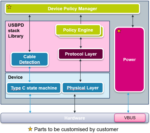
The Power Delivery protocol is provided by ST as a library as shown in the following picture:
The customer application is in DPM (Device Policy Manager). This is where the strategy (choose the maximum power...) is coded. The library (light pink box) only includes PE (Policy Engine), PRL (PRotocol Layer), and a part of CAD (CAble Detection). This library is common to all STM32 including the UCPD IP and is provided as a certified toolbox. The source code of the library is not available, because ST has certified the USB power delivery state machines. The customer just needs to adapt the DPM and the power parts. The device part depends on the STM32 family (STM32G0, STM32G4...)
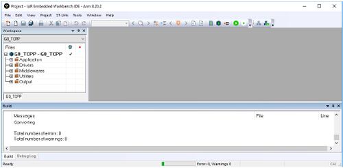
Here is a USBPD project example in IAR:
In all our project examples, different folders can be found:
- The Application/User folder contains the source files that we need to edit to enrich the application, particularly the *_user.c files.
- The Drivers folder contains the HAL drivers for the STM32.
- The Middleware folder contains the source files and the libraries for FreeRTOS™ and USB-PD stack.
- The Utilities folder contains the GUI (STM32CubeMonitor-UCPD) and tracer embedded source files part.
- The Output folder contains the compilation result files.
![]() How to build an USBPD Sink application using the X-Cube-TCPP software pack
How to build an USBPD Sink application using the X-Cube-TCPP software pack
![]() How to build an USBPD Source application using the X-Cube-TCPP software pack
How to build an USBPD Source application using the X-Cube-TCPP software pack
![]() How to build an USBPD Dual-Role application using the X-CUBE-TCPP software pack
How to build an USBPD Dual-Role application using the X-CUBE-TCPP software pack
4. STM32 integrating UCPD IP for USB Power Delivery
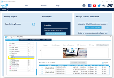
If you are looking for STM32 products that support Power Delivery, you can search in STM32CubeMX for the integration of the UCPD peripheral. STM32G0 is the only family with parts that contain up to 2 UCPD instances.
5. Specific tools
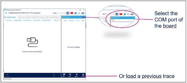
- STM32CubeMonitor-UCPD for USB-C and Power Delivery is a tool to debug and configure the stack. UM2468
The STM32CubeMonitor-UCPD speeds up the development and the debugging of the user application. It allows seeing the internal states of the USB Power delivery stack, when the tracer feature is activated (Compilation switch: _TRACE). It also allows customizing the stack if the related firmware part that will respond to the PC tool (Compilation switch _GUI_INTERFACE) is activated.
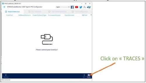
If the GUI responder is not activated in the embedded firmware (It is the case for the STM32G071B-DISCO when the blue door is open = spy mode), when the _TRACE compilation switch is enabled, the debug information is available (UART through VCP of the STLink) and the traces in UCPD monitor can be accessed by clicking on the Trace button in the bottom right corner.
The trace files are saved in c:\Users\%username%\AppData\Local\Temp\STM32CubeMonitor-UCPD\Acquisition\ with ".cpd" extension.
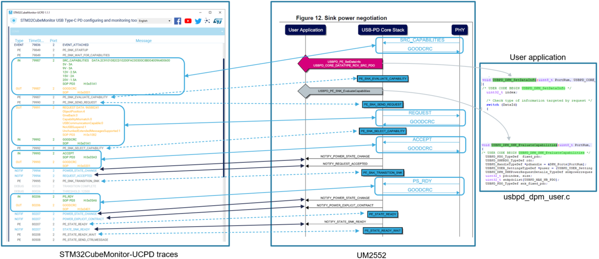
The cpd files are a pretty good entry point to report an issue to our support team, it provides helpful debug information of the USB-PD stack behavior. The traces helps you to link with the flowcharts described in the UM2552, as shown in the below example :
6. STMicroelectronics Resources
- USB Type-C and Power Delivery solutions page
- The general application note describing how to do power delivery with the STM32. AN5225
- The USBPD stack user manual UM2552.
- The AN5418 is a simple application note guiding the creation of a Sink application with STM32CubeMX. Watch the video
7. USB data management
For the integration of the USB data into a USBD-PD application, the stack library CORE versions must be above v4.0.0 to include a new usb if there is a model file to simplify the work. The principle is based on the notification mechanism used to inform the application when an event occurs. The stack has been updated to trigger dedicated USB events when a USB data action is required. The instructions below explain how to update your application :
- Inside the stack you will find usbpd_usb_if_template.c/h which needs to be copied into your application and populated with the USB code.
- Update the function USBPD_DPM_Notification inside the file usbpd_dpm_user.c
void USBPD_DPM_Notification(uint8_t PortNum, USBPD_NotifyEventValue_TypeDef EventVal)
{
  switch(EventVal)
  {
    case USBPD_NOTIFY_USBSTACK_START:
    {
	if (USBPD_PORTDATAROLE_DFP == DPM_Params[PortNum].PE_DataRole)
	{
	  USBPD_USBIF_HostStart(PortNum);
	}
	else
	{
	  USBPD_USBIF_DeviceStart(PortNum);
	}
	break;
    }
    case USBPD_NOTIFY_USBSTACK_STOP:
    {
	 if (USBPD_PORTDATAROLE_DFP == DPM_Params[PortNum].PE_DataRole)
	 {
	  USBPD_USBIF_HostStop(PortNum);
	 }
	 else
	 {
	  USBPD_USBIF_DeviceStop(PortNum);
	 }
	 break;
  }
   case USBPD_NOTIFY_DATAROLESWAP_DFP :
   {
    USBPD_USBIF_Swap2Host(PortNum);
    break;
   }
  case USBPD_NOTIFY_DATAROLESWAP_UFP :
  {
    USBPD_USBIF_Swap2Device(PortNum);
    break;
  }
}
8. Application examples
8.1. STM32Cube FW Packages
You can find a lot of application examples in the different STM32Cube firmware packages:
For example, in Projects\STM32G081B-EVAL\Demonstrations\DemoUCPD
Or if you have downloaded the package through STM32CubeMX: c:\Users\your_login\STM32Cube\Repository\STM32Cube_FW_G0_V1.6.1\
| MCU | Ref. board | Power role | User Manual | Application path |
|---|---|---|---|---|
| G0 | STM32G071B-Disco | SNK | UM2546 | |
| STM32G081B-Eval | Dual port: DRP & SNK |
UM2783 | ||
| STM32G0C1E-Eval | Dual port: DRP & SNK |
UM2321 | ||
| G4 | B-G474E-DPOW1 | SNK | UM2557 | |
| STM32G474E-EVAL | DRP | UM2514 | ||
| L5 | STM32L552E-EVAL | SNK | UM2597 | |
| NUCLEO-L552ZE-Q | SNK | UM2581 | ||
| U5 | B-U585I-IOT02A | SNK | UM2539 | |
| STM32U575I-EV | SRC | UM2839 | ||
| H5 | NUCLEO-H563ZI | SNK | UM3115 | |
| STM32H573I-DK | SRC | UM3143 | ||
| H7RS | NUCLEO-H7S3L8 | DRP | UM3276 | |
| STM32H7S78-DK | DRP | UM3289 |
8.2. X-CUBE-TCPP
X-CUBE-TCPP is an STMicroelectronics original initiative. It uses for USB Type-C and Power Delivery software expansion for STM32Cube (UM2285).
X-CUBE-TCPP is a USB-IF certified Expansion Package (**USB Type-C Rev 2.0 and Power Delivery 3.1 with 100 W PPS support**) and consists of libraries, drivers, sources, APIs and application examples running on STM32 Series GP microcontrollers embedding Type-C and power delivery management (thanks to the embedded UCPD PHY integrated in STM32G4, STM32G0 and STM32L5).
For the other STM32 GP MCU without embedded UCPD PHY (like STM32L4, STM32F0...), this package demonstrates how to comply with Type-C specification.
All the applications available in this package need to have the TCPP01-M12 integrated. The TCPP01-M12 (Type-C port protection) is a single chip solution for USB Type-C port protection that facilitates the migration from USB legacy connectors type-A or type-B to USB Type-C connectors.
| Applications | Board | Shield | Short Description |
|---|---|---|---|
| USBPDM1_Sink_PPS | NUCLEO-G071RB | X-NUCLEO-USBPDM1 | Use of USB Power Delivery (USB-PD) Consumer application (with **PPS**) running on STM32G0XX devices, with X-NUCLEO-USBPDM1 shield plugged. |
| USBPDM1_Sink_LPM | NUCLEO-G071RB | X-NUCLEO-USBPDM1 | Use of USB Power Delivery (USB-PD) Consumer application (with **Low Power Mode**) running on STM32G0XX devices, with X-NUCLEO-USBPDM1 shield plugged. |
| USBPDM1_Sink | NUCLEO-G474RE | X-NUCLEO-USBPDM1 | Use of USB Power Delivery (USB-PD) Consumer application running on STM32G4XX devices, with X-NUCLEO-USBPDM1 shield plugged. |
| SNK1M1_Sink | NUCLEO-G071RB | X-NUCLEO-SNK1M1 | Use of USB Power Delivery (USB-PD) Consumer application (with **PPS**) running on STM32G0XX devices, with X-NUCLEO-SNK1M1 shield plugged. |
| SNK1M1_Sink | NUCLEO-G474RE | X-NUCLEO-SNK1M1 | Use of USB Power Delivery (USB-PD) Consumer application (with **PPS** and **USB MSC** cohabitation) running on STM32G4XX devices, with X-NUCLEO-SNK1M1 shield plugged. |
| SNK1M1_Sink_TypeC_Only | NUCLEO-L412RB-P | X-NUCLEO-SNK1M1 | Use of Type-C Consumer application (with **USB MSC** enumeration) running on STM32L4XX devices, with X-NUCLEO-SNK1M1 shield plugged. |
See also a dedicated wiki article on:
- How to build your USB-PD Sink application with STM32CubeMX: STM32 Advance USB-Power Delivery Sink
- How to build your USB-PD Source application with STM32CubeMX: STM32 Advance USB-Power Delivery Source
9. FAQ
9.1. How to connect the trace TRACER_EMB with no ST-LINK on my board?
There are two ways to visualize debug trace and USBPD protocol information without onboard ST-LINK:
1- Use a UART TX available pin, and connect it to the RX pin of any external ST-LINK you have.
2- Use a UART to USB converter like the one in: CP210x )
Then, you need to update the file tracer_emb_conf.h to indicate which GPIO you use. STM32CubeMX can do it for you: refer to AN5418 chapter 5.2.1
9.2. Why cannot I get a higher voltage contract?
If you stay to 5V contracts when testing a sink, and you cannot get a higher voltage using STM32CubeMonitor-USBPD, look in your trace if you have the message: "PE_EvaluateCapability: could not find desired voltage"
 Type	Time	Port	Message
 IN	8575	0	SRC_CAPABILITIES    DATA:2C9101082CD10200FAC00300C8B0040096400600  / 5V - 3A  / 9V - 3A  / 12V - 2.5A  / 15V - 2A  / 20V - 1.5A	SOP	 PD3	    H:0x51A1
 OUT	8575	0	GOODCRC	SOP		    H:0x0001
 PE	8575	0	PE_SNK_EVALUATE_CAPABILITY
 DEBUG	8577	0	PE_EvaluateCapability: could not find desired voltage
It means that your PDO defined for your sink cannot find any matching PDOs on the source side. You probably send a 5V request, using PDO number one :
OUT 17508 1 REQUEST DATA: F4B10414 / ObjectPosition:1 / GiveBack:0 / CapabilityMismatch:1 / USBCommunicationCapable:0 / NoUSBSuspend:0 / UnchunkedExtendedMessagesSupported:0 SOP PD3 H:0x1082
It could be that in your sink PDOs, you request too much current, and your source cannot support such requests. Check your PDOs either in the file usbpd_pdo_defs.h, or if you have activated the utility (_GUI_INTERFACE switch), in the STM32CubeMonitor-USBPD "Port Configuration/SINK Capabilities" tab. Perhaps your operational current is too high for what your source can provide?
9.3. How to analyze the failed return by the function USBPD_DPM_InitCore?
This function is called at the init stage to initialize the USB-PD application (device and stack part)
  /* Check the lib selected */
  if (USBPD_TRUE != USBPD_PE_CheckLIB(_LIB_ID))
  {
    return USBPD_ERROR;
  }
At this stage, the software is checking if the LIB files selected to build the project and the compilation switch USBPDCORE_LIB****** are aligned.
Definition available in usbpd_def.h
  /* _LIB_ID definition */
  /*
    _LIB_ID constructs like this: 0xXYVVVWWW
    * X: 3 (PD3.0) or 2 (PD2.0)
    * Y: 0 (CORE) or 1 (TCPM)
    * VVV: Stack version (ex 200 for Stack 2.0.0)
    * WWW: 0 (FULL VERSION) or config_x
  */
For instance, if the lib 'USBPDCORE_PD3_FULL_CM*.*' is selected, the user should enable the switch 'USBPDCORE_LIB_PD3_FULL'
9.4. How to know the memory needed by the stack?
This is done dynamically in the stack, depending on the linked USBPD library :
stack_dynamemsize = USBPD_PE_GetMemoryConsumption();
This stage is optional (could be removed) and only present to know how much memory is needed in the USB-PD stack to help define the correct value of the HEAP.
9.5. How to insert my own debug information inside the trace system?
9.5.1. Use firmware module TRACER_EMB
To have the debugged trace inside embedded code (very useful for real-time debugging, thanks to the timestamps), you can use the TRACER_EMB utility to send trace over STLink virtual COM port / UART. You have to use the USBPD_TRACE_Add function from file usbpd_trace.c, to print information inside the GUI tools
USBPD_TRACE_Add(USBPD_TRACE_DEBUG, 'port number', 'trace id', 'string', 'string size');
For example :
USBPD_TRACE_Add(USBPD_TRACE_DEBUG, 0, 0, "hello world", 11);
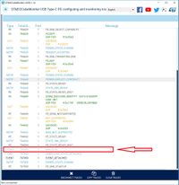
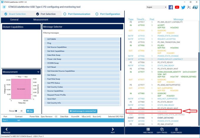
In the below pictures, check the line "DEBUG hello world" in gray.
The numbers indicated in the trace are the TimeStamp and the port number. (TimeStamp can be practical to debug real-time issues)
1- when GUI_INTERFACE is disabled (click to enlarge):
2- when GUI_INTERFACE is enabled. (Click to enlarge).
9.5.2. Display VBUS level
9.5.2.1. Using USER button
For further debug, the VBUS measured value can be printed in the trace, using the user button. Add in src/main.c:
  /**
  * @brief EXTI line detection callbacks
  * @param GPIO_Pin Specifies the pins connected EXTI line
  * @retval None
  */
  void HAL_GPIO_EXTI_Falling_Callback(uint16_t GPIO_Pin)
  {
  	if (GPIO_Pin == USER_BUTTON_PIN) /* Displays in trace the VBUS value when the user button is pressed */
  	{
  		char _str[10];
  		BSP_PWR_VBUSGetVoltage(0);
  		sprintf(_str,"VBUS:%d", BSP_PWR_VBUSGetVoltage(0));
  		USBPD_TRACE_Add(USBPD_TRACE_DEBUG, 0, 0, (uint8_t*)_str, strlen(_str));
  	}
  }
and the corresponding interrupt in src/stm32g0xx_it.c:
  /**
  * @brief This function handles the external line 4_15 interrupt request.
  * @retval None
  */
  void EXTI4_15_IRQHandler(void)
  {
  	HAL_GPIO_EXTI_IRQHandler(USER_BUTTON_PIN);
  }
9.5.2.2. Using 'Send free text' Feature in CubeMonitor-UCPD
There is a friendly feature in CubeMonitor-UCPD to trig some actions from the computer, through UART/ VCP, called 'Send free text'.
- Enable GUI_INTERFACE in your project
- Register a user callback to manage the interaction with CubeMonitor-UCPD:
USBPD_StatusTypeDef DisplayVBUS(uint8_t PortNum, uint8_t * pData, uint16_t Size);
...
  GUI_RegisterCallback_FreeText(DisplayVBUS);
- Implement the callback function to display the VBUS value in the log as soon as user write "HELP" (as example here), and click on 'Send free text':
USBPD_StatusTypeDef DisplayVBUS(uint8_t PortNum, uint8_t * pData, uint16_t Size);
{
  if (memcmp(pData, "HELP", Size) == 0)
  {
    USBPD_TRACE_Add(USBPD_TRACE_DEBUG, PortNum, 0, "USE FREETEXT!", strlen("USE FREETEXT!"));
  }
  else
  {
    char _str[10];
    BSP_PWR_VBUSGetVoltage(PortNum);
    sprintf(_str,"VBUS:%d", BSP_PWR_VBUSGetVoltage(PortNum));
    USBPD_TRACE_Add(USBPD_TRACE_DEBUG, PortNum, 0, (uint8_t*)_str, strlen(_str));
  }
  return USBPD_OK;
}
- Enter 'HELP' (for example), and then click on "Send message" to trig the action of displaying VBUS value message :
9.6. How can I check the CC line level?
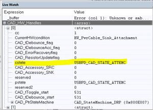
- Add livewatch on CAD_HW_Handles in your favorite IDE, and look for the cstate parameter.
This variable can be used to check the Type-C attachment or detachment. Refer to usbpd_cad_hw_if.c.
- If the CC lines do not change, and you are using a protection IC on the CC lines, TCPP0x for example, check that this protection is pass through, which means for the TCPP0x that the active LOW _DB pin is disabled at 3.3 V.
Note: If you have an issue on the CC2 for STM32G4, verify that in usbpd_cad_hw_if.c you put the CC2 line to the analog mode. You should have: LL_GPIO_SetPinMode(GPIOB, LL_GPIO_PIN_4, LL_GPIO_MODE_ANALOG);
9.7. Why a request function returned USBPD_OK but I cannot see the message in the trace?
All the request functions (like USBPD_DPM_RequestDataRoleSwap) do not trig directly the sending of the message to the port partner. The idea is to post a request to the stack and when the stack is ready, it consumes this request to send it to the port partner.
Note1: only 1 request is possible. Another request sent whereas the previous one is not yet consumed is not taken into account (USBPD_BUSY status is returned).
Note2: USBPD_BUSY is also returned if there are no connected port partner.
9.8. About FreeRTOS™ in our stack
Tasks creations are done in usbpd_dpm_core.c file.
At the initialization, the USB-PD creates 2 threads:
- CAD Task: used for the cable detection (higher priority in our system set to osPriorityRealtime)
- TRA_TX: used to evacuate the debug trace (set to osPriorityLow priority)
When the Type-C is connected, we create a dynamic task for PE_TASK set to a priority lower than CAD, osPriorityAboveNormal (done through callback ‘USBPD_DPM_CADCallback’. It allows starting a PD negotiation. The task is killed if a detachment is done.
In usbpd_dpm_user.c, we create also a task for DPM set as low priority
- DPM task: used mainly to manage the specification to be done after the timer expiration like:
- Management of ALERT messages
- Management of SRC_CAPA_EXT messages …
- Management of ALERT messages
Two different scenarios:
1- No Type-C cable connected:
- In DRP mode, we have a CAD toggle to switch every 40 ms from Source (present Rp) to Sink (present Rd). Then the CAD task is woken up regularly (every 40 ms)
- In SRC or SNK mode, CAD is woken up if an event occurs on the CC lines (through ‘USBPD_DPM_CADCallback’ function)
2- Type-C cable connected:
- If the Power Delivery negotiation is OK, CAD and PE should wait for a new event, and CAD is woken up:
- In SRC: due to an event on the CC lines (through ‘USBPD_DPM_CADCallback’ function)
- In SNK: every 10 ms or an event on the CC lines, PE is woken up only if a message is sent or received (through the ‘USBPD_PE_TaskWakeUp’ function)
- Negotiation failed:
- In SNK, CAD is woken up every 10 ms or if an event occurs on the CC lines
- In SRC, if no answer from the port partner:
- PE_CapscounterSupport = 0: PE wakes up every 150 ms
- PE_CapscounterSupport = 1: the system wakes up only after a change on the CC lines
Normally, during the CAD/PE sleep, FreeRTOS™ must leave control to other tasks having a lower priority (thanks to the osDelay function for instance). There is no real reason for another task with less priority to take control.
9.9. SNK PDO selection policy in DPM
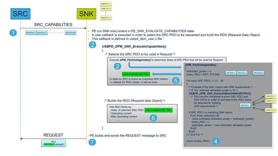
On the SNK side, when SRC capabilities are received from the SRC port, the SNK has to select the SRC PDOs which are used for building the REQUEST message to be sent to the attached SRC port. The selection of this PDO among all available SRC PDOs is under the responsibility of SNK and achieved through a DPM callback, called by PE during the Explicit Contract negotiation.
The callback which determines the PDO that the SNK tries to request, is the USBPD_DPM_SNK_EvaluateCapabilities() function.
This function (executed on the SNK side) aims to identify the PDO within those presented by the SRC, which matches the SNK requirements as much as possible.
In the demonstration code, the current content of USBPD_DPM_SNK_EvaluateCapabilities() code, provides an example of the SNK PDO selection policy, aiming to select the SRC PDO which provides the maximum power according to the SNK requirements.
This part of the SNK port implementation is described in the below scheme:
The current policy is now implemented in demonstration projects available in STM32G0, G4, or L5 firmware packages:
- STM32G0 firmware package : Projects\STM32G081B-EVAL\Demonstrations\DemoUCPD
- STM32G4 firmware package : Projects\STM32G474E-EVAL\Demonstrations\Demo
- STM32L5 firmware package : Projects\STM32L552E-EV\Demonstrations\Demo
This is only an example and this policy could be updated according to application needs. For example, if application wants to implement its own policy of selection of the SRC PDO to use in the REQUEST message, it could be done in DPM_FindVoltageIndex() function.
9.10. Why is the PD message not sent by the stack?
The Policy Engine schedules the PD message to be sent with a system of timers. If the timers are not managed (decremented) the stack cannot send the message. To avoid this issue, check if the function USBPD_DPM_TimerCounter is called inside SysTick_Handler (file stm32xxxx_it.c) or any tick system management.
        void SysTick_Handler(void)
        {
             USBPD_DPM_TimerCounter();
             HAL_IncTick();
        }
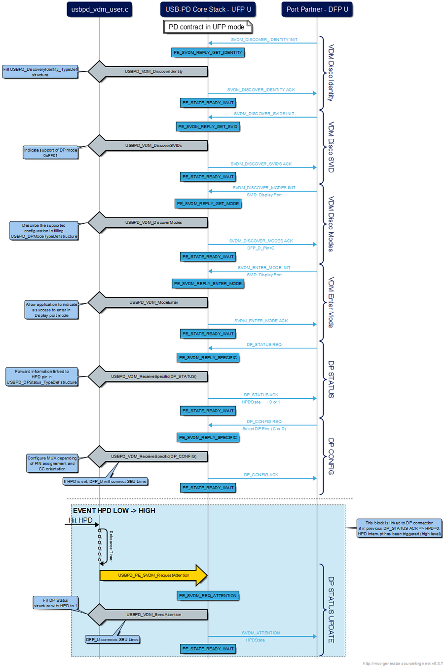
9.11. How DP does it work on EVAL-G081 demonstration?
This part describes the mechanism used in our demonstration to be able to connect a laptop to a screen through the Port2_Sink port. This is an add-on of the description done in UM2321 (4.3.7 Display Port demonstration, Fig.63)
G0 role is to:
- Detect connection of laptop on Type-C:
- establish a PD contract
- if contract is established in SRC/DFP configuration, application has to request a data role swap for switching in UFP mode (cf Figure 36. Data role swap generation in UM2552)
- configure MUX (DL and AUX lines) according to the CC orientation and Laptop request (VDM negociation)
- establish a PD contract
- Detect HPD pin linked to a connection/disconnection on DP port (screen)
- May send SVDM attention message to laptop to indicate a connection/disconnection of DP cable
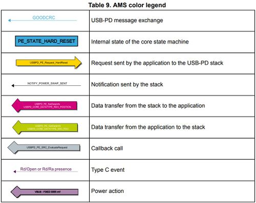
The following picture is based on convention defined in UM2552 (§4)
All the user code lines can be found in the usbpd_vdm_user.c file available in the EVAL-G081 demonstration.
Moreover, ST provides a DP connector based on STM32F0: STEVAL-USBC2DP. A technical note is provided with this board: TA0356
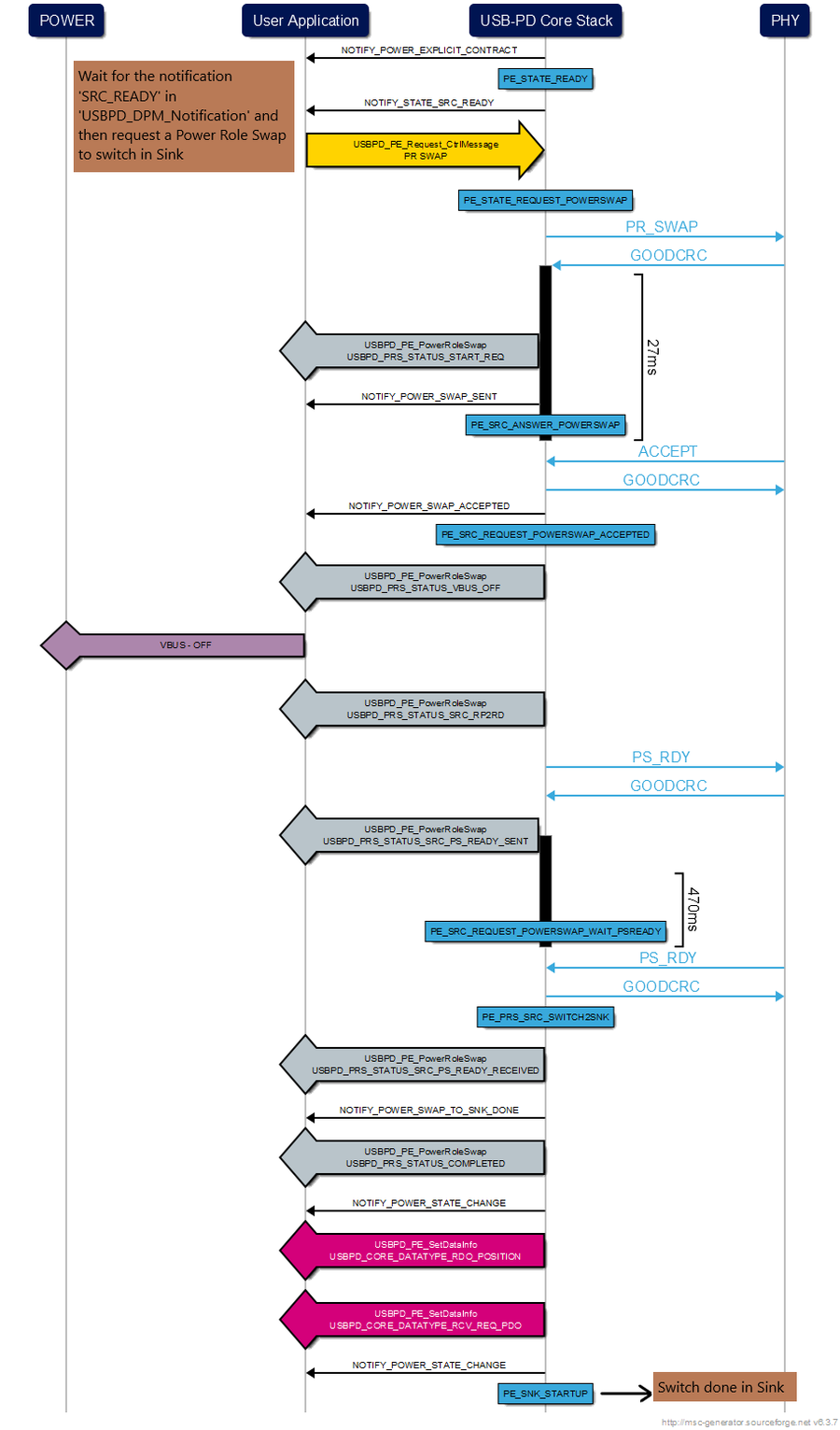
9.12. How to request a switch in sink mode when my device has started in source mode?
If two DRP devices are connected, the arbitrary choice is to start either in source or sink mode (Dual Role toggle in CAD). In the case my device starts in source, I can request the stack to send a Power Role Swap to the partner port for a switch of power role.
Please find a Message Sequence Chart describing this scenario :
In your source code (file 'usbpd_dpm_user.c'), the following code needs to be added:
 void USBPD_DPM_Notification(uint8_t PortNum, USBPD_NotifyEventValue_TypeDef EventVal)
 {
   /* USER CODE BEGIN USBPD_DPM_Notification */
   USBPD_StatusTypeDef status;
   switch(EventVal)
   {
    case USBPD_NOTIFY_STATE_SRC_READY:
    {
      /* Request a PRS to SNK */
      status = USBPD_DPM_RequestPowerRoleSwap(PortNum) ;
      break;
   }
   /* USER CODE END USBPD_DPM_Notification */
 }

