1. External Memory Loader
1.1. What is a loader?
A loader is a set of functions grouped together in binary format that are individually called by a host tool to perform actions on a dedicated memory. The loader is loaded by the tools inside a volatile RAM space and its execution is managed by the host tool.
The loader characteristics are:
- Binary format: the loader is a binary file that uses continuous RAM space for code and data.
- Loader file: the loader file is an ELF file (with symbol information).
- Interrupt: the interrupts are disabled since it is a recommendation for the host tool to keep control over the execution flow.
- Stack: the loader does not allocate memory space to the stack.
- RAM buffer: there is no space allocated to store the data to be written.
- Mapped mode: this is the preferred mode for checking written data.
1.2. External Memory Loader architecture
The External Memory Loader is middleware developed for STM32 that consists of a core component and target entry points for the loader.
The core component is composed of the following two subcomponents:
- memory_wrapper: an abstraction layer that provides basic memory services based on the STM32 middleware External Memory Manager API.
- systick: a SysTick management wrapper is used to make the SysTick timer functional without interrupts. It is used as the HAL time base.
1.3. Loader mechanism in IDEs
To run a loader, three components are essential:
- A host tool, such as an IDE (for example, IAR, Keil, or STM32CubeIDE) or a loader utility program (sucha s STM32CubeProgrammer)
- A binary format loader containing code and symbol information
- An STM32 board with embedded external flash memory
The loader host tool operates as follows:
- Read the loader file to retrieve loader functions and memory information.
- Load the code into the internal volatile RAM of the STM32 device.
- Allocate space in RAM for the RAM buffer and stack.
- Call loader functions to load the firmware into the external memory.
Main loader operations
The main loader operations are:
- Initialize the external memory.
- Erase the memory by sector or with a mass erase.
- Write the RAM buffers with code into external memory.
- Verify the external memory downloaded content.
1.3.1. STM32Cube
STM32Cube loader configuration file
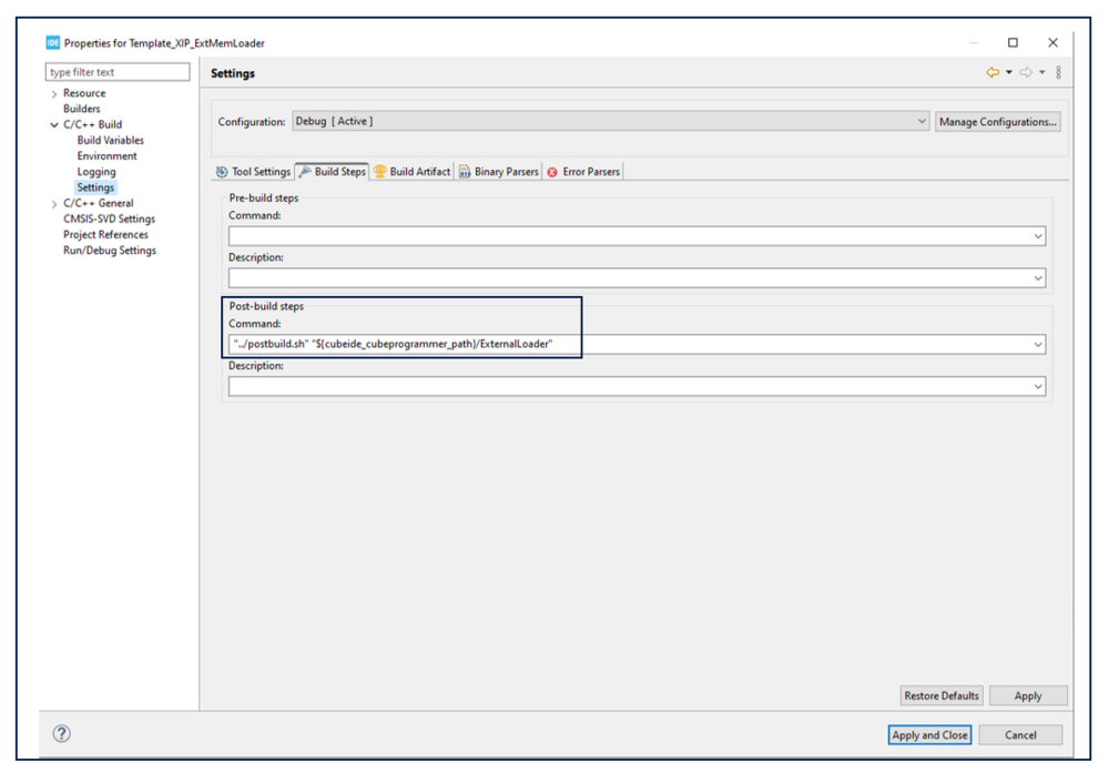
No configuration is needed; the External Memory Loader is copied automatically to STM32CubeProgrammer using the postbuild.sh shell script, which is responsible for automating the configuration of the generated loader in STM32CubeProgrammer.
1.3.2. EWARM (IAR IDE)
IAR loader configuration file
- Flash memory configuration file (.flash): XML file that describes the memory elements to the debugger. This includes, for example, the flash memory base address, the flash loader name, and the flash memory characteristics, such as block and page size.
- Flash memory system configuration file (.board) : XML file that specifies the information needed to perform flash memory loading for a specific board. This file can be prepared in advance for various development boards, and created or modified in the IAR Embedded Workbench IDE.
1.3.3. MDK-ARM (Keil IDE)
MDK-ARM loader configuration file
The generated *.FLM file needs to be added to the pack with device support, so that it is available to the IDE tool for programming the device. Usually, a Flash directory is created and the algorithm is saved in this directory.
The algorithm is specified within at the /package/devices/family level:

- The argument start= specifies the base address for the flash memory programming algorithm.
- The argument size= specifies the size covered by the flash memory programming algorithm. End address = start + size - 1.
- The argument default= specifies whether a flash memory programming algorithm is set as the default algorithm in a project (when true).


