Click here for Bluetooth® Low Energy Overview.
1. Introduction
STM32CubeMX tool is a graphical tool that helps you to generate a first application targeting the MCU of your choice, with initialization code based on the configuration you specify. In the tools interface, you can select the right MCU, configure pins, clocks, peripherals, middleware, and it generates code project based on your setup.
This wiki page defines how to generate a Bluetooth® Low Energy (BLE) server custom application for STM32WB55RG MCU using STM32CubeMX software.
2. Build a Bluetooth® Low Energy application on STM32WB with CubeMX
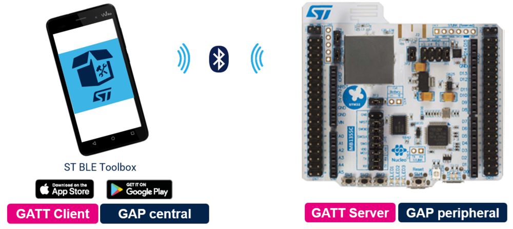
The STM32WB Nucleo board, flashed with the application generated by STM32CubeMX, can send data to a smartphone (using ST BLE ToolBox application), and receive commands from it through Bluetooth® Low Energy.
This GATT Server application shall be able to expose two services:
- First service exposes two characteristics
- Second service exposes three characteristics
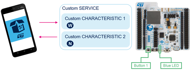
The first service (My_P2P_Server) looks like P2P Server (STM proprietary) with two characteristics:
- Characteristic 1 has Write property
- Characteristic 2 has Notify property
Writing to characteristic 1 toggles blue LED.
Pressing SW1 on Nucleo board send data to the phone
The second service (My_Heart_Rate) is build as a SIG Heart Rate, but the behavior won't be managed.
The following steps are recommended to build this application example:
Services and Characteristics configuration are given in the following table:
| Service Long Name | My_P2P_Server | My_Heart_Rate | |||
|---|---|---|---|---|---|
| Service Short Name | My_P2P | My_HRS | |||
| UUID Type | 128 bits | 16 bits | |||
| UUID | 0xFE40 | 0x180D | |||
| Characteristic Long Name | My_LED_Char | My_Switch_Char | My_HRS_Meas | My_Sensor_Loc | My_HRS_CTL_Point |
| Characteristic Short Name | LED_C | SWITCH_C | HRS_M | HRS_SL | HRS_CTRLP |
| UUID Type | 128 bits | 128 bits | 16 bits | 16 bits | 16 bits |
| UUID | 0xFE41 | 0xFE42 | 0x2A37 | 0x2A38 | 0x2A39 |
| Char Properties | Read + Write w/o response | Notify | Notify | Read | Write |
| Char Permissions | None | None | None | None | None |
| Char GATT Events | GATT_NOTIFY_ATTRIBUTE_WRITE | GATT_NOTIFY_ATTRIBUTE_WRITE | None | None | GATT_NOTIFY_WRITE_AND_WAIT_FOR_A_PPL_RESP |
3. Tools
3.1. Software tools
To make and use this project, the needed software tools to complete the application are:
- STM32CubeMX[1] software (from v6.4.0)
- STM32CubeWB MCU Package[2] (from v1.13.1)
- IDE: STM32CubeIDE[3] or IAR[4]
- Serial Terminal (TeraTerm[5])
- Smartphone application ST BLE ToolBox
3.2. Hardware tools
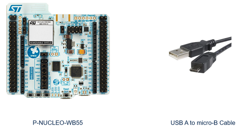
A STM32WB Nucleo board and a micro-B to Type-A USB cable are also needed.
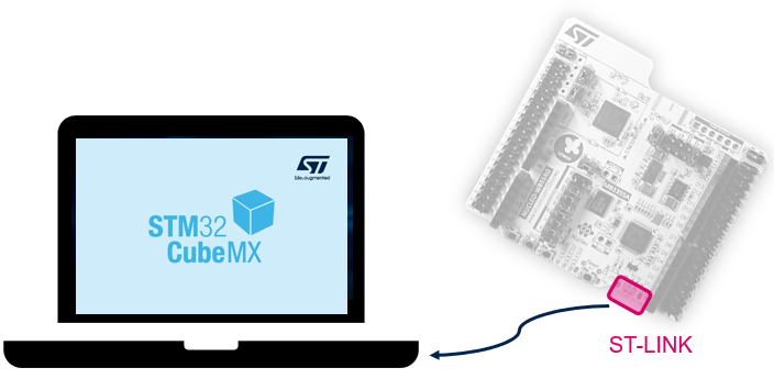
The PC is connected to the ST-LINK connector of the NUCLEO board (right connector from the top view).
4. CubeMX initialization for P-NUCLEO-WB55
4.1. STM32CubeMX initial setup
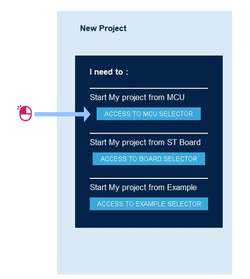
Open STM32CubeMX and start a new project from the Access to MCU selector button
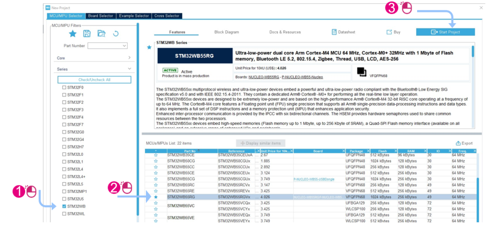
Chose the MCU and then start the new project:
4.2. Pinout and IP configuration
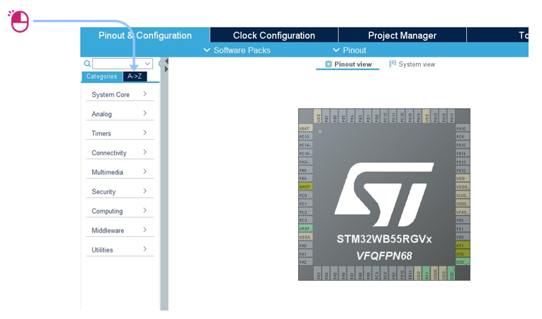
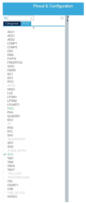
To configure the system, enable all the required system resource and peripherals clicking on A->Z to display all IPs.
BLE mode is reachable once the following system resources and peripherals are turned to enable.
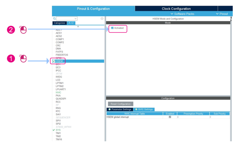
- HSEM :activated
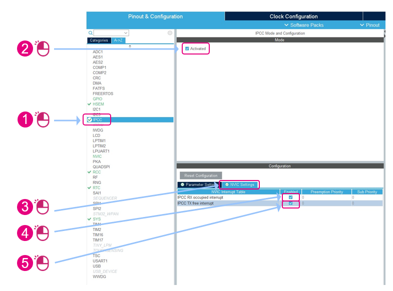
- IPCC : activated, ITs enabled
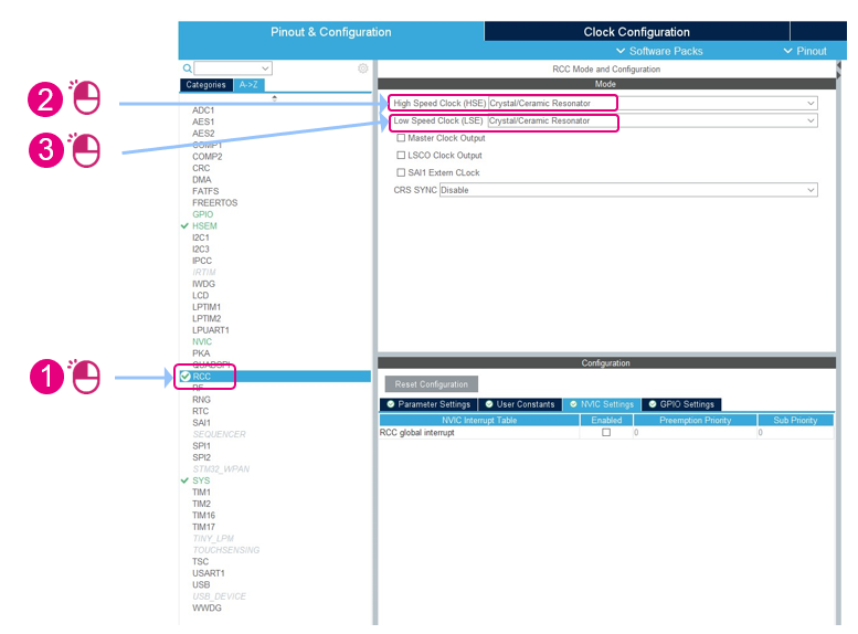
- RCC : HSE and LSE on Crystal/Ceramic resonator
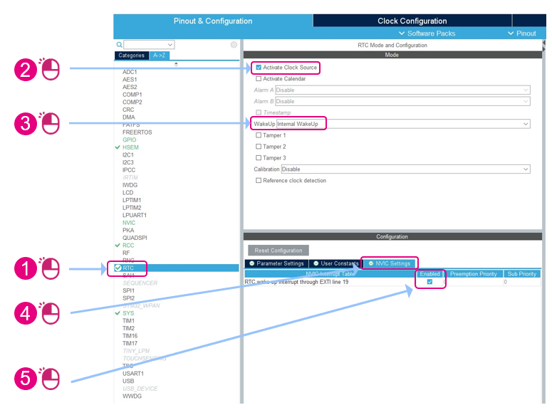
- RTC : activate clock source and enable internal wakeup
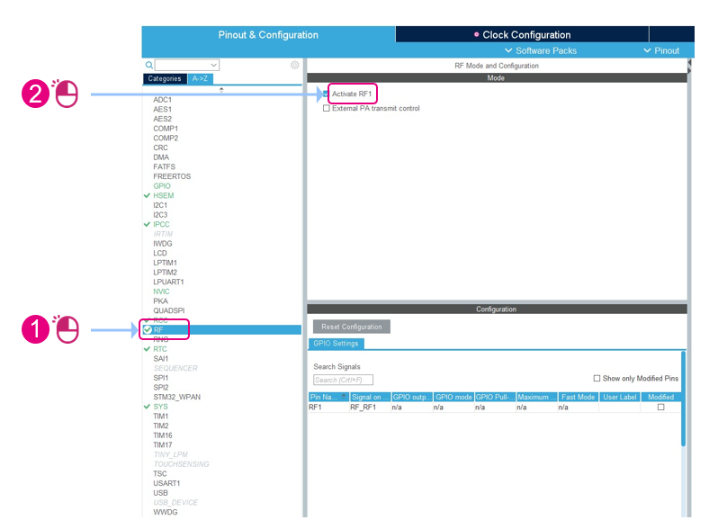
- RF : activate RF1
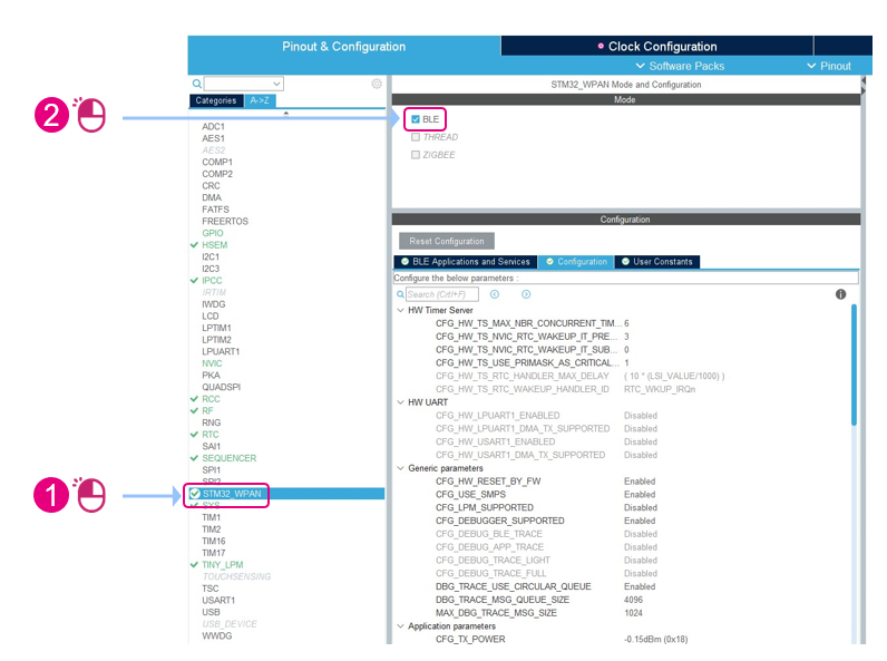
- STM32WPAN : BLE
4.2.1. HSEM
The Hardware SEMaphore (HSEM) is needed to manage shared resources between the two CPU cores in the STM32WB.
4.2.2. IPCC
Configuration of Inter-Processor Controller Communication (IPCC) is done as follows:
4.2.3. RCC
On Reset and Clock Controller (RCC), High Speed clock (HSE) and Low Speed Clock (LSE) are mandatory for Bluetooth® LE radio.
4.2.4. RTC
Configuration of Real Time Counter (RTC) is done as follows:
4.2.5. RF
Activate RF1:
4.2.6. Enable BLE
Finally, under STM32_WPAN interface, check BLE box:
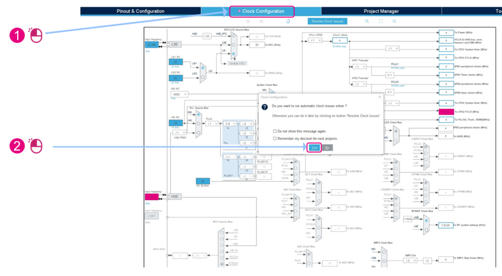
4.3. Clock configuration
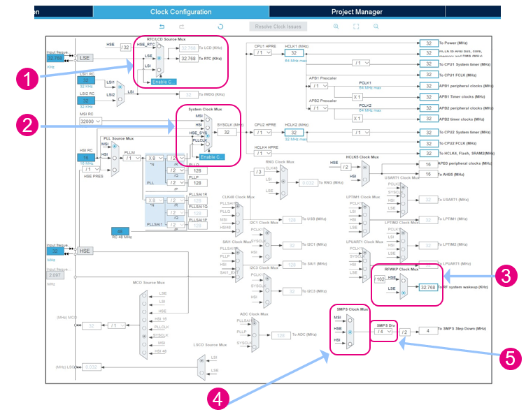
On clock configuration tab, run the automatic clock issue solver:
Then:
4.4. Project manager
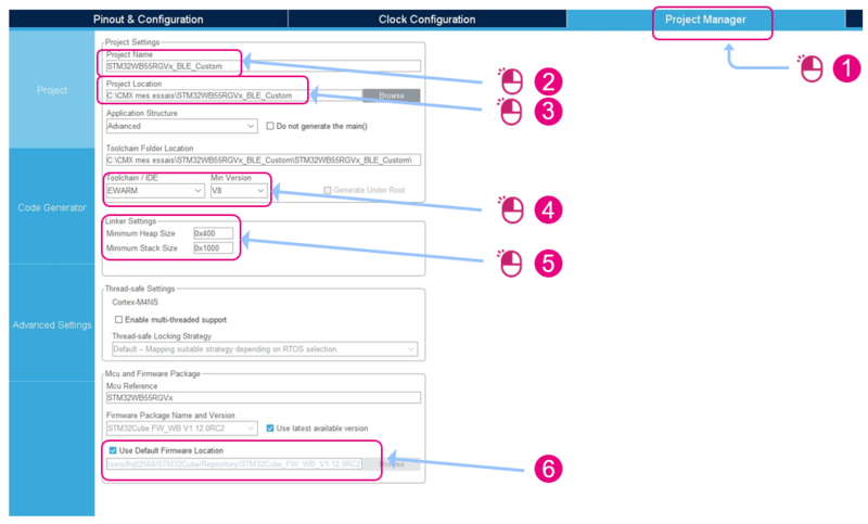
All the project configuration is done on the Project Manager pane within three sections, and done as follows :
4.4.1. Project
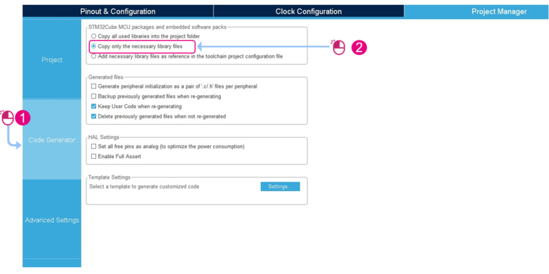
4.4.2. Code generator
Manages files, packages and embedded software packs
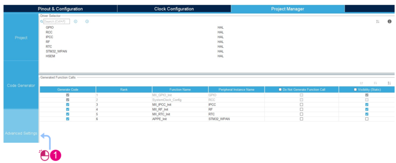
4.4.3. Advanced settings
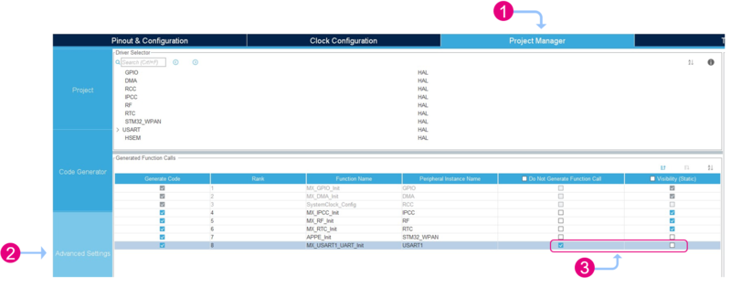
Definition of drivers to use (HAL/LL) and generated function calls.
- Uncheck Do Not Generate Function Call checkbox for APPE_Init
5. BLE GAP/GATT Custom application configuration
Now, we can start configuring and defining the BLE middleware.
- Bluetooth® LE Peripheral Custom Template GATT Server Application can be defined:
- On STM32WB
- With STM32CubeMX
- GAP peripheral : advertising configuration
- GATT server configuration:
- five services maximum
- five characteristics maximum per service
- ACI commands:
- AN5270: STM32WBx5 Bluetooth® Low Energy (BLE) wireless interface[6].
- AN5270: STM32WBx5 Bluetooth® Low Energy (BLE) wireless interface[6].
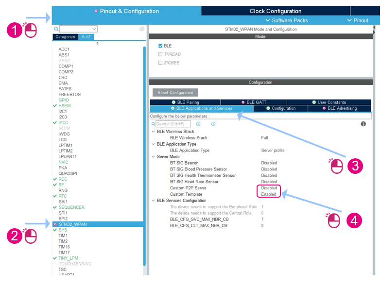
5.1. BLE applications and services
To start the definition of the Bluetooth® LE application :
5.2. Advertising configuration
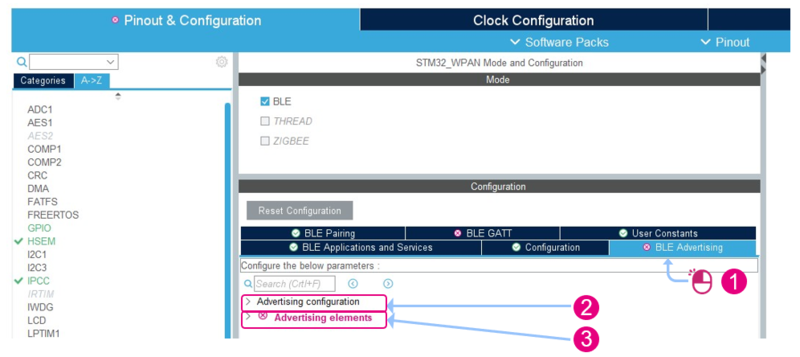
Advertising parameters are defined under BLE Advertising tab:
- advertising configuration data are located in app_conf.h and ble_conf.h files
- advertising elements data are located in app_ble.c file
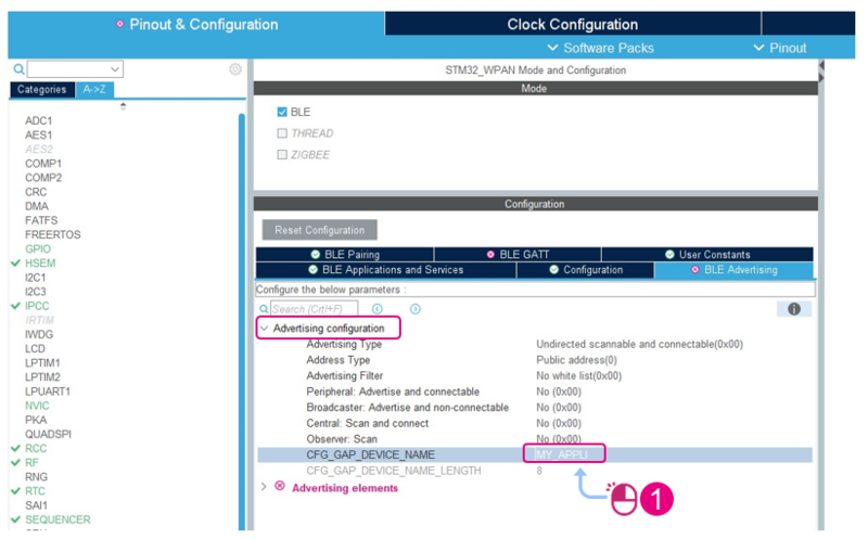
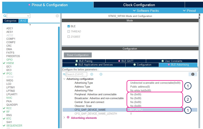
Open Advertising Configuration and set the CFG_GAP_DEVICE_NAME to something of your liking, for example MY_APPLI.
In the generated code these parameters are defined in :
1. app_conf.h file:
- #define ADV_TYPE
- #define BLE_ADDR_TYPE
- #define FILTER
- #define CFG_GAP_DEVICE_NAME
2. ble_conf.h file:
- #define BLE_CFG_PERIPHERAL
- #define BLE_CFG_CENTRAL
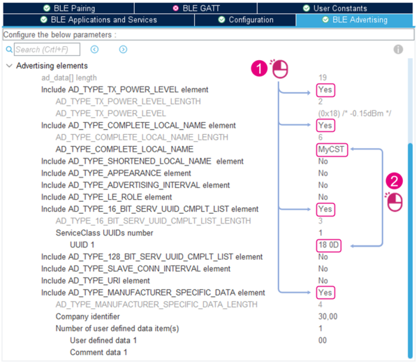
In Advertising elements:
- Turn to “yes” the elements to add in the advertising packet payload as described in the image below
 :
:
- Tx power: AD_TYPE_TX_POWER_LEVEL
- Complete local name: AD_TYPE_COMPLETE_LOCAL_NAME
- 16 bits service UUID: AD_TYPE_16_BIT_SERV_UUID_CMPLT_LIST
- Manufacturer specific data: AD_TYPE_MANUFACTURER_SPECIFIC_DATA - Set the value for the other elements as mentioned in the image below
 :
:
- Complete Local name: AD_TYPE_COMPLETE_LOCAL_NAME = MyCST
- Service 1 UUID: UUID 1 = 180D
The advertising information is represented by advertising data elements, which are standardized on the Bluetooth SIG.
These elements are included in the advertising packet payload and are located in app_ble.c file (here the advertising packet structure’s length = 19 bytes).
5.3. Services and characteristics definition
All created services and characteristics are managed in custom_stm.c file. Each service and characteristic is added in SVCCTL_InitCustomSvc() function using:
- aci_gatt_add_service(…) for services,
- aci_gatt_add_char(…) for characteristics.
5.3.1. Services definition
Each created service is defined in a dedicated CubeMX tab:
- Up to five characteristics per service
- UUID type can be defined as 16 or 128 bits
- UUID definition
- Type value is primary or secondary service
A custom application can define up to five services.
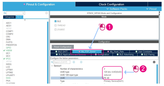
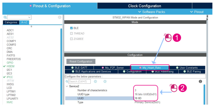
In the following example, we define two services, My_P2P_Server and My_Heart_Rate.
You can set the number of services to define in the BLE GATT tab (present in STM32_WPAN interface):
For each defined service ![]() , set the number of characteristics and the service UUID value as defined in the following images
, set the number of characteristics and the service UUID value as defined in the following images ![]() .
.
two characteristics for My_P2P_Server service and service UUID is 0xFE40.
three characteristics for My_Heart_Rate service and service UUID is 0x180D.
5.3.2. Characteristics definition
For each characteristic the following parameters must be defined
- General
- Properties
- Permissions
- GATT events
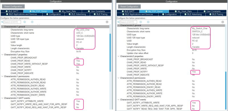
My_P2P_Server Characteristics:
My_P2P_Server service have 2 characteristics:
- First characteristic:
- Long name: My_LED_Char
- Short name: LED_C
- UUID type: 128 bits UUID(0x02)
- UUID 128 input type: reduced
- UUID: 0xFE41
- Value length: 2
- Length characteristic: Variable
- Properties: CHAR_PROP_READ and CHAR_PROP_WRITE_WITHOUT_RESP
- GATT events: only GATT_NOTIFY_ATTRIBUTE_WRITE
- Second characteristic:
- Long name: My_Switch_Char
- Short name: SWITCH_C
- UUID type: 128 bits UUID(0x02)
- UUID 128 input type: reduced
- UUID: 0xFE42
- Value length: 2
- Length characteristic: Variable
- Properties: CHAR_PROP_NOTIFY
- GATT events: only GATT_NOTIFY_ATTRIBUTE_WRITE
Defined as follows:
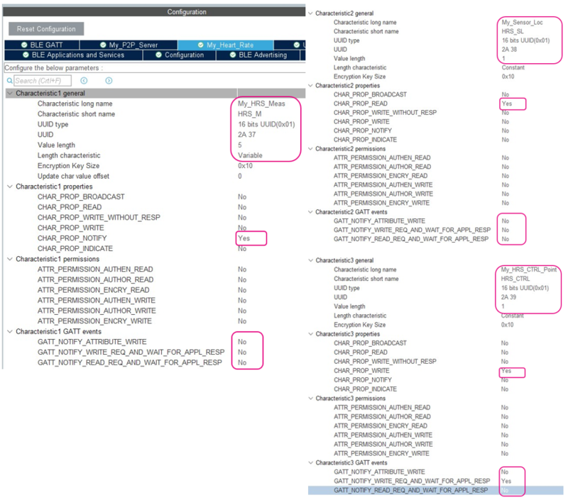
My_Heart_Rate Characteristics:
My_Heart_Rate service have three characteristics, with respective short name HRS_M, HRS_SL and HRS_CTRL.
- First characteristic:
- Long name: My_HRS_Meas
- Short name: HRS_M
- UUID type: 16 bits UUID(0x01)
- UUID: 0x2A37
- Value length: 5
- Length characteristic: Variable
- Properties: CHAR_PROP_NOTIFY
- GATT events: None
- Second characteristic:
- Long name: My_Sensor_Loc
- Short name: HRS_SL
- UUID type: 16 bits UUID(0x01)
- UUID: 0x2A38
- Value length: 1
- Properties: CHAR_PROP_READ
- GATT events: None
- Third characteristic:
- Long name: My_HRS_CTRL_Point
- Short name: HRS_CTRL
- UUID type: 16 bits UUID(0x01)
- UUID: 0x2A39
- Value length: 1
- Properties: CHAR_PROP_WRITE
- GATT events: only GATT_NOTIFY_WRITE_REQ_AND_WAIT_FOR_APPL_RESP
Defined as follows:
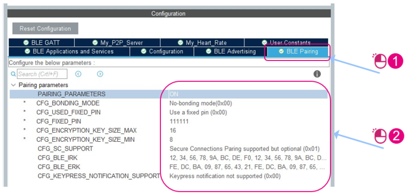
5.3.3. Pairing definition
Pairing is done to support secure connection method.
All pairing parameters defined in the BLE_Pairing tab are located in app_conf.h file.
When PAIRING_PARAMETERS is set to ON, pairing parameters are available on the interface and can be defined as follows:
Once configuration is done in STM32CubeMX, the code can be generated by following the steps described in Code Generation chapter.
If you want to enable traces before generating the project, go to next chapter.
If you want to setup User button and LED, you can refer to P2P Server: Notifications and Writes management chapter.
6. Enable traces
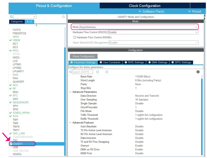
6.1. USART configuration
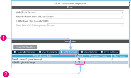
Go to USART1 setup interface and select Asynchronous Mode:
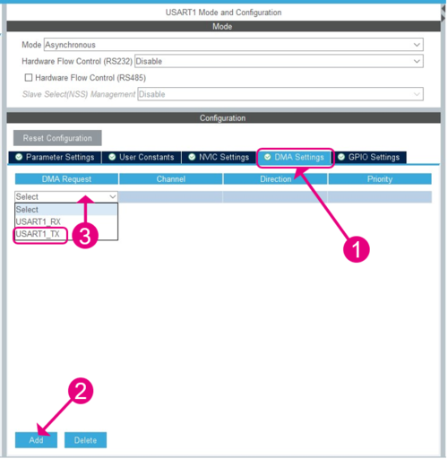
Then, go to DMA Settings tab ![]() , click on Add button
, click on Add button ![]() and select USART1_TX
and select USART1_TX ![]() .
.
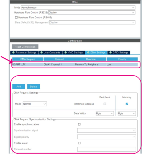
Ensure DMA1 Channel1 is selected, and click on USART1_TX line to show DMA Request Settings.
Go to NVIC Settings tab ![]() and enable USART1 global interrupt
and enable USART1 global interrupt ![]() .
.
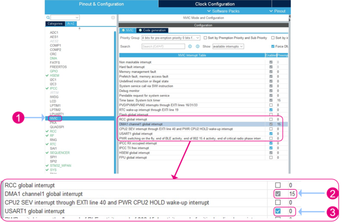
6.2. NVIC configuration
Go to NVIC Settings interface ![]() and set DMA1 Channel 1 global interrupt Preemption Priority to 15 (lowest priority)
and set DMA1 Channel 1 global interrupt Preemption Priority to 15 (lowest priority) ![]() .
.
Check that USART1 global interrupt is enabled ![]() .
.
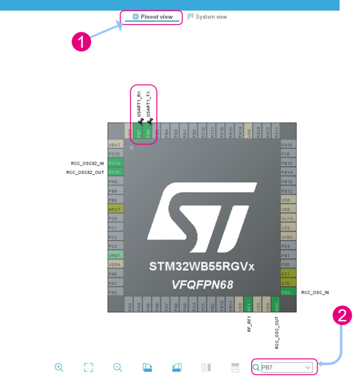
6.3. USART1 pinout definition
Go to Pinout view ![]() .
.
Set UASRT1_TX on PB6 and USART1_RX on PB7:
- Click on PB6
- Select USART1_TX in the list
- Click on PB7
- Select USART1_RX in the list
You can use the search located in the bottom right of the pinout view window ![]() to find a pin or signal name easily (here PB6 and PB7)
to find a pin or signal name easily (here PB6 and PB7)
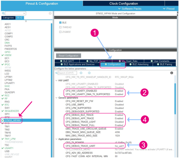
6.4. STM32_WPAN configuration
Go to STM32_WPAN setup interface and select the Configuration tab ![]() .
.
Enable the application traces ![]() , set CFG_DEBUG_TRACES_UART on hw_uart1
, set CFG_DEBUG_TRACES_UART on hw_uart1 ![]() .
.
Configure the debug traces to manage the different types of logs ![]() .
.
6.5. Project manager settings
Go to Project Manager interface ![]() and select the Advanced Settings tab
and select the Advanced Settings tab ![]() .
.
Configure MX_UASRT1_UART_Init function ![]() as:
as:
- Check Do Not Generate Function Call checkbox.
- Uncheck Visibility (Static) checkbox.
Once the traces configuration is done in STM32CubeMX, the code can be generated by following the steps described in Code Generation chapter.
6.6. Add USER CODE section in app_entry.c
In order to make the application able to manage debug messages, app_entry.c file must be updated.
In MX_APPE_Init() function, add a call to APPD_Init() function into the USER CODE APPE_Init_1 section as follows:
void MX_APPE_Init( void )
{
  System_Init( );       /**< System initialization */

  SystemPower_Config(); /**< Configure the system Power Mode */

  HW_TS_Init(hw_ts_InitMode_Full, &hrtc); /**< Initialize the TimerServer */

/* USER CODE BEGIN APPE_Init_1 */
  APPD_Init();
/* USER CODE END APPE_Init_1 */
  appe_Tl_Init();	/* Initialize all transport layers */
Open a debug terminal as TeraTerm connected on USART1 to display application messages. Refer to TeraTerm Setup chapter.
7. P2P Server notifications and writes management
In order to use P2P Server Notification and Write characteristics, several points have to be configured:
- User Button and the related Interrupt, to Notify the P2P Client
- Blue LED, to receive a P2P Client write operation
- Custom application code to manage SW1 and write operation on P2P Server service
7.1. User button and LED pinout
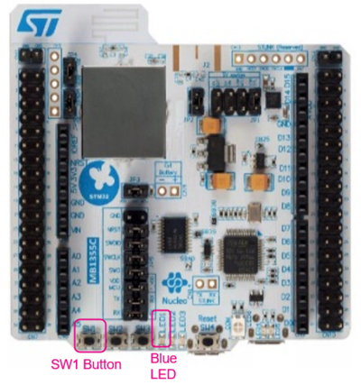
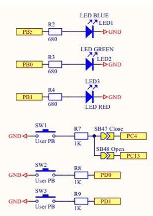
In the Nucleo board, LED pinout is:
- Blue LED : PB5
- Green LED: PB0
- Red LED: PB1
Switch (user button) pinout is:
- SW1: PC4
- SW2: PD0
- SW3: PD1
When used:
- Switch pins are declared as GPIO_EXTIx (x = pin number)
- LED pins are declared as GPIO_OUTPUT
7.2. Blue LED setup
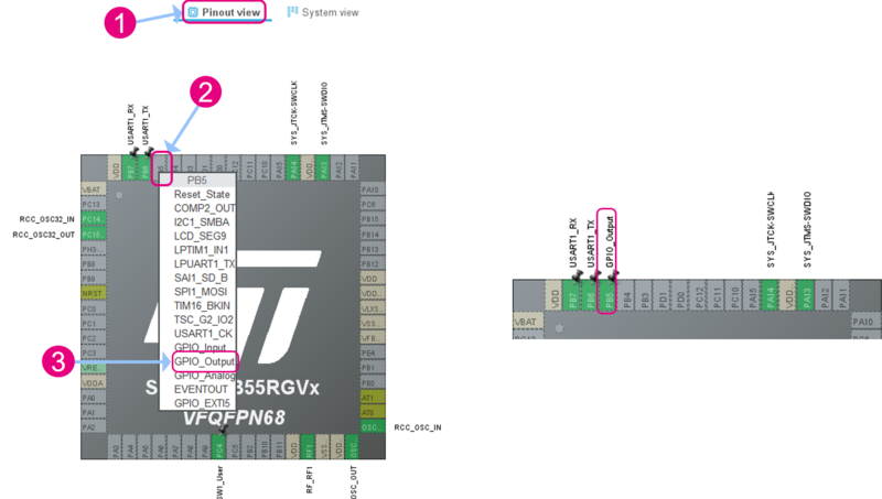
Go to Pinout and Configuration -> Pinout View Interface ![]() , click on PB5
, click on PB5 ![]() and select GPIO_OUTPUT
and select GPIO_OUTPUT ![]() .
.
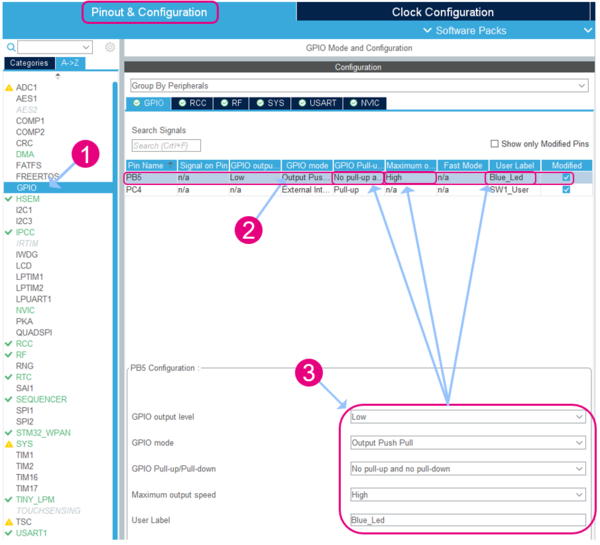
In pinout and configuration interface, go to the GPIO tab ![]() .
.
Select the GPIO line corresponding to PB5 ![]() and configure the PB5 configuration pane
and configure the PB5 configuration pane ![]() as follows:
as follows:
- GPIO Mode: Output Push/Pull
- GPIO Pull-up/Pull-down: No Pull-up and no pull-down
- Maximum outpus speed: High
- User Label: Blue_Led
This generate the following Blue_Led GPIO pin and port definitions in main.h:
7.3. SW1 button setup
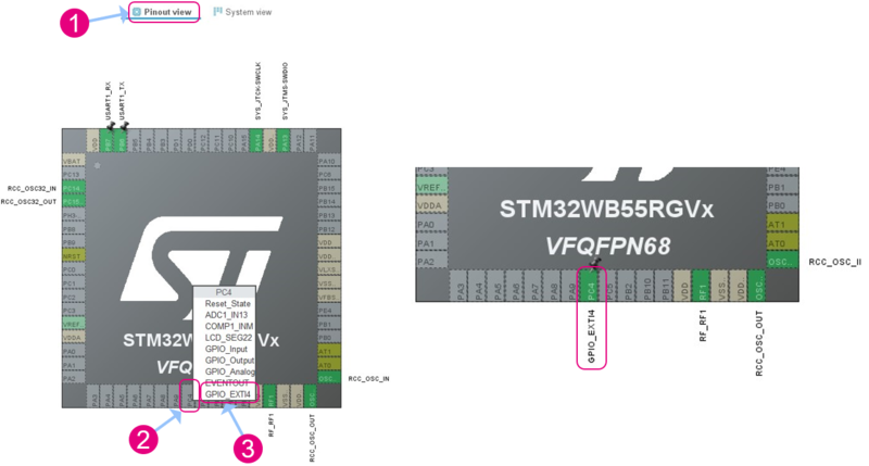
Go to Pinout & Configuration -> Pinout View Interface ![]() , click on PC4
, click on PC4 ![]() and select GPIO_EXTI4
and select GPIO_EXTI4 ![]() .
.
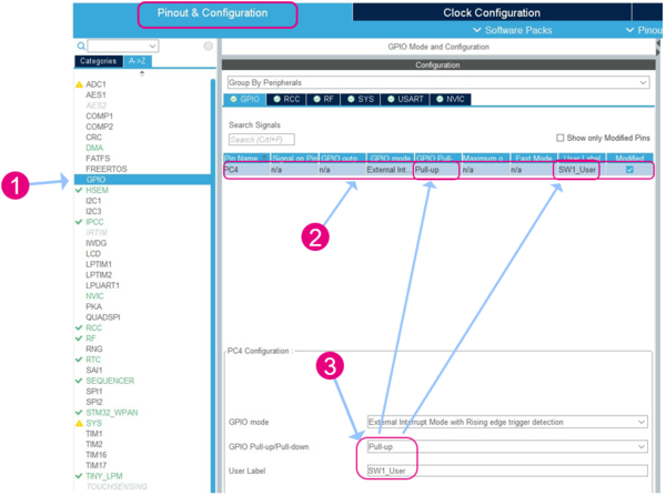
In Pinout & Configuration interface, go to the GPIO tab ![]() .
.
Select the GPIO line corresponding to PC4 ![]() and configure the PC4 configuration pane
and configure the PC4 configuration pane ![]() as follows:
as follows:
- GPIO Mode: External Interrupt Mode with Rising edge trigger detection
- GPIO Pull-up/Pull-down: Pull-up
- User Label: SW1_User
This generate the following SW1_User GPIO pin and port definitions in main.h:
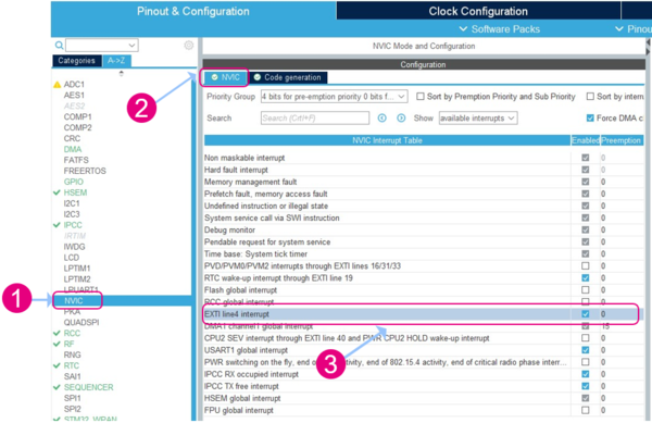
Go to NVIC interface ![]() and click on the NVIC tab
and click on the NVIC tab ![]() .
.
Enable the EXTI line4 interrupt ![]() , this interrupt corresponds to SW1.
, this interrupt corresponds to SW1.
7.4. Code modification: User sections
Once your SW1 Button and Blue LED GPIOs are correctly setup, generate your project by following the steps described in Code Generation chapter.
The generated source code contains several sections called User Sections where users can add custom application code parts.
These sections are not erased/modified at project regeneration from CubeMX.
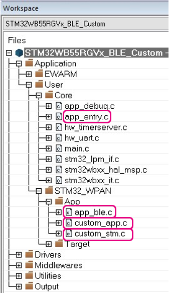
In order to manage SW1 and write operation on P2P Server service, some code parts have to be added in User Sections of the following files and their respective header files:
- In app_conf.h:
Define the task for the characteristic My_Switch_Char of My_P2P_Server by adding code in CFG_Task_Id_With_HCI_Cmd_t User Code Section:
/**< Add in that list all tasks that may send a ACI/HCI command */
typedef enum
{
    CFG_TASK_ADV_CANCEL_ID,
#if (L2CAP_REQUEST_NEW_CONN_PARAM != 0)
    CFG_TASK_CONN_UPDATE_REG_ID,
#endif
    CFG_TASK_HCI_ASYNCH_EVT_ID,
/* USER CODE BEGIN CFG_Task_Id_With_HCI_Cmd_t */
    CFG_TASK_SW1_BUTTON_PUSHED_ID,                                              /* Code Line to add */
/* USER CODE END CFG_Task_Id_With_HCI_Cmd_t */
    CFG_LAST_TASK_ID_WITH_HCICMD,                                               /**< Shall be LAST in the list */
} CFG_Task_Id_With_HCI_Cmd_t;
- In app_entry.c:
Define the callback for handling the interrupts from SW1 presses by adding code in FD_WRAP_FUNCTIONS User Code Section:
/* USER CODE BEGIN FD_WRAP_FUNCTIONS */
void HAL_GPIO_EXTI_Callback(uint16_t GPIO_Pin)
{
  switch (GPIO_Pin)
  {
    case BUTTON_SW1_PIN:
      APP_BLE_Key_Button1_Action();
      break;
    default:
      break;
  }
  return;
}
/* USER CODE END FD_WRAP_FUNCTIONS */
- In app_ble.c:
Define function for SW1 action by adding code in FD_SPECIFIC_FUNCTIONS User Code Section:
/* USER CODE BEGIN FD_SPECIFIC_FUNCTIONS */
void APP_BLE_Key_Button1_Action(void)
{
  P2PS_APP_SW1_Button_Action();
}
/* USER CODE END FD_SPECIFIC_FUNCTIONS */
- In app_ble.h:
Declare the APP_BLE_Button1_Action() function, in EF User Code Section:
/* Exported functions ---------------------------------------------*/
  void APP_BLE_Init( void );

/* USER CODE BEGIN EF */
void APP_BLE_Key_Button1_Action(void);        /* Code Line to add */
/* USER CODE END EF */
- In custom_app.h:
Declare P2PS_APP_SW1_Button_Action function, in EF User Code Section:
/* Exported functions ---------------------------------------------*/
  void Custom_APP_Init( void );
  void Custom_APP_Notification( Custom_App_ConnHandle_Not_evt_t *pNotification );
/* USER CODE BEGIN EF */
  void P2PS_APP_SW1_Button_Action(void);        /* Code Line to add */
/* USER CODE END EF */
- In custom_app.c:
Add SW1_Status variable in CUSTOM_APP_Context_t User Code Section:
/* Private typedef -----------------------------------------------------------*/
typedef struct
{
  /* My_P2P_Server */
  uint8_t               Switch_c_Notification_Status;
  /* My_Heart_Rate */
  uint8_t               Hrs_m_Notification_Status;
  /* USER CODE BEGIN CUSTOM_APP_Context_t */
  uint8_t               SW1_Status;                      /* Code Line to add */
  /* USER CODE END CUSTOM_APP_Context_t */

  uint16_t              ConnectionHandle;
} Custom_App_Context_t;

/* USER CODE BEGIN PTD */

/* USER CODE END PTD */
In the same file, update snippets shown. The following traces code is to indicate the Smartphone requests to enable or disable notifications and write requests on My_P2P_Server service.
In CUSTOM_STM_LED_C_WRITE_NO_RESP_EVT User Section:
/* Functions Definition ------------------------------------------------------*/
void Custom_STM_App_Notification(Custom_STM_App_Notification_evt_t *pNotification)
{
  /* USER CODE BEGIN CUSTOM_STM_App_Notification_1 */

  /* USER CODE END CUSTOM_STM_App_Notification_1 */
  switch(pNotification->Custom_Evt_Opcode)
  {
    /* USER CODE BEGIN CUSTOM_STM_App_Notification_Custom_Evt_Opcode */

    /* USER CODE END CUSTOM_STM_App_Notification_Custom_Evt_Opcode */

  /* My_P2P_Server */
    case CUSTOM_STM_LED_C_READ_EVT:
      /* USER CODE BEGIN CUSTOM_STM_LED_C_READ_EVT */

      /* USER CODE END CUSTOM_STM_LED_C_READ_EVT */
      break;

    case CUSTOM_STM_LED_C_WRITE_NO_RESP_EVT:
      /* USER CODE BEGIN CUSTOM_STM_LED_C_WRITE_NO_RESP_EVT */
      APP_DBG_MSG("\r\n\r** CUSTOM_STM_LED_C_WRITE_NO_RESP_EVT \n");
      APP_DBG_MSG("\r\n\r** Write Data: 0x%02X %02X \n", pNotification->DataTransfered.pPayload[0], pNotification->DataTransfered.pPayload[1]);
      if(pNotification->DataTransfered.pPayload[1] == 0x01)
      {
        BSP_LED_On(LED_BLUE);
      }
      if(pNotification->DataTransfered.pPayload[1] == 0x00)
      {
        BSP_LED_Off(LED_BLUE);
      }
     /* USER CODE END CUSTOM_STM_LED_C_WRITE_NO_RESP_EVT */
      break;
In CUSTOM_STM_SWITCH_C_NOTIFY_ENABLED_EVT and CUSTOM_STM_SWITCH_C_NOTIFY_DISABLED_EVT User Sections:
case CUSTOM_STM_SWITCH_C_NOTIFY_ENABLED_EVT:
      /* USER CODE BEGIN CUSTOM_STM_SWITCH_C_NOTIFY_ENABLED_EVT */
      APP_DBG_MSG("\r\n\r** CUSTOM_STM_BUTTON_C_NOTIFY_ENABLED_EVT \n");

      Custom_App_Context.Switch_c_Notification_Status = 1;        /* My_Switch_Char notification status has been enabled */
      /* USER CODE END CUSTOM_STM_SWITCH_C_NOTIFY_ENABLED_EVT */
      break;

    case CUSTOM_STM_SWITCH_C_NOTIFY_DISABLED_EVT:
      /* USER CODE BEGIN CUSTOM_STM_SWITCH_C_NOTIFY_DISABLED_EVT */
      APP_DBG_MSG("\r\n\r** CUSTOM_STM_BUTTON_C_NOTIFY_DISABLED_EVT \n");

      Custom_App_Context.Switch_c_Notification_Status = 0;        /* My_Switch_Char notification status has been disabled */
      /* USER CODE END CUSTOM_STM_SWITCH_C_NOTIFY_DISABLED_EVT */
      break;
Add code snippets in Custom_App_Init() function to register the send notification task that is started when SW1 button is pressed, in CUSTOM_APP_Init User Section:
void Custom_APP_Init(void)
{
  /* USER CODE BEGIN CUSTOM_APP_Init */
  UTIL_SEQ_RegTask(1<< CFG_TASK_SW1_BUTTON_PUSHED_ID, UTIL_SEQ_RFU, Custom_Switch_c_Send_Notification);

  Custom_App_Context.Switch_c_Notification_Status = 0;
  Custom_App_Context.SW1_Status = 0;

  /* USER CODE END CUSTOM_APP_Init */
  return;
}
And code snippet to allow the task to run once SW1 is pressed, in FD_LOCAL_FUNCTIONS User Section:
/* USER CODE BEGIN FD_LOCAL_FUNCTIONS*/
  void P2PS_APP_SW1_Button_Action(void)
  {
    UTIL_SEQ_SetTask(1<<CFG_TASK_SW1_BUTTON_PUSHED_ID, CFG_SCH_PRIO_0);

    return;
  }
/* USER CODE END FD_LOCAL_FUNCTIONS*/
Add code snippet for sending notification request to the smart phone, in Switch_c_NS User Section:
void Custom_Switch_c_Send_Notification(void) /* Property Notification */
 {
  if(Custom_App_Context.Switch_c_Notification_Status)
  {
    Custom_STM_App_Update_Char(CUSTOM_STM_SWITCH_C, (uint8_t *)NotifyCharData);
    /* USER CODE BEGIN Switch_c_NS*/
    if (Custom_App_Context.SW1_Status == 0)
    {
      Custom_App_Context.SW1_Status = 1;
      NotifyCharData[0] = 0x00;
      NotifyCharData[1] = 0x01;
    }
    else
    {
      Custom_App_Context.SW1_Status = 0;
      NotifyCharData[0] = 0x00;
      NotifyCharData[1] = 0x00;
    }

    APP_DBG_MSG("-- CUSTOM APPLICATION SERVER  : INFORM CLIENT BUTTON 1 PUSHED \n");
    APP_DBG_MSG(" \n\r");
    Custom_STM_App_Update_Char(CUSTOM_STM_SWITCH_C, (uint8_t *)NotifyCharData);

    /* USER CODE END Switch_c_NS*/
  }
  else
  {
    APP_DBG_MSG("-- CUSTOM APPLICATION : CAN'T INFORM CLIENT -  NOTIFICATION DISABLED\n");
  }
  return;
}
- In custom_stm.c:
Update Custom_STM_Event_Handler() function to manage My_LED_Char write, in CUSTOM_STM_Service_1_Char_1_ACI_GATT_ATTRIBUTE_MODIFIED_VSEVT_CODE User Section:
static SVCCTL_EvtAckStatus_t Custom_STM_Event_Handler(void *Event)
{
  […]
 event_pckt = (hci_event_pckt *)(((hci_uart_pckt*)Event)->data);

  switch(event_pckt->evt)
  {
    case HCI_VENDOR_SPECIFIC_DEBUG_EVT_CODE:
      blecore_evt = (evt_blecore_aci*)event_pckt->data;
      switch(blecore_evt->ecode)
      {
        case ACI_GATT_ATTRIBUTE_MODIFIED_VSEVT_CODE:
        […]
          else if(attribute_modified->Attr_Handle == (CustomContext.CustomLed_CHdle + CHARACTERISTIC_VALUE_ATTRIBUTE_OFFSET))
          {
            return_value = SVCCTL_EvtAckFlowEnable;
            /* USER CODE BEGIN CUSTOM_STM_Service_1_Char_1_ACI_GATT_ATTRIBUTE_MODIFIED_VSEVT_CODE */
            Notification.Custom_Evt_Opcode = CUSTOM_STM_LED_C_WRITE_NO_RESP_EVT;
            Notification.DataTransfered.Length=attribute_modified->Attr_Data_Length;
            Notification.DataTransfered.pPayload=attribute_modified->Attr_Data;
            Custom_STM_App_Notification(&Notification);
            /* USER CODE END CUSTOM_STM_Service_1_Char_1_ACI_GATT_ATTRIBUTE_MODIFIED_VSEVT_CODE */
          } /* if(attribute_modified->Attr_Handle == (CustomContext.CustomLed_CHdle + CHARACTERISTIC_VALUE_ATTRIBUTE_OFFSET))*/
          /* USER CODE BEGIN EVT_BLUE_GATT_ATTRIBUTE_MODIFIED_END */

          /* USER CODE END EVT_BLUE_GATT_ATTRIBUTE_MODIFIED_END */
          break;
7.5. ST BLE toolbox: P2P server notification and write
If you are not familiar with ST BLE ToolBox application, a first introduction is available on ST BLE Toolbox Application chapter.
1. Scan and connect
Open a serial terminal (see: TeraTerm Configuration chapter) and connect your smartphone to your board using ST BLE ToolBox application.
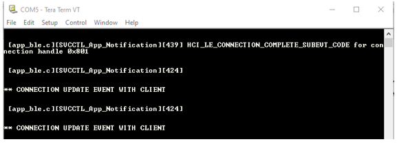
Once connected, the following message is displayed on TeraTerm.
2. P2P Server Notification
Search and open P2P Server service.
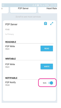
Enable P2P Notify, on characteristic FE42 to receive notification from the STM32WB Nucleo board, using SW1 button as configured in previous example.
- When notifications have been enabled, the application displays the following message on the terminal:
- In the same way, when notifications are disabled, the following debug message is displayed on the terminal:
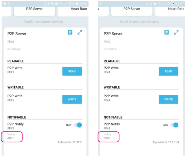
Once notifications enabled, press SW1 button on Nucleo board to notify the P2P Server Characteristic.
The P2P Notify characteristic value toggles each time the SW1 button is pressed.
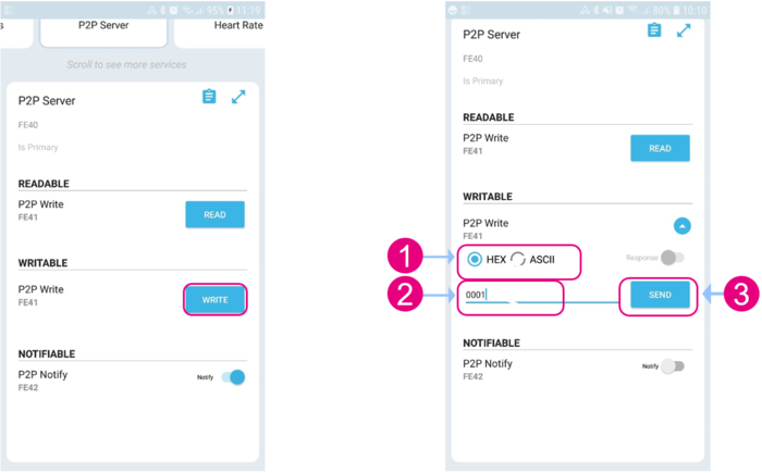
3. P2P Write
Using FE41 (LED_C) characteristic which is defined as a Write Without Response property, the P2P service writes data to the STM32WB Nucleo Board.
Press WRITE button and select Hexadecimal format ![]() , then define the data to write
, then define the data to write ![]() and press SEND button
and press SEND button ![]() to write it in the LED_C characteristic.
to write it in the LED_C characteristic.
- Writing 0x0000 in 0xFE41 characteristic switch the LED 1 OFF.
- Writing 0x0001 in 0xFE41 characteristic switch the LED 1 ON.
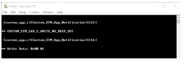
On the debug terminal, the message with the written data is displayed.
8. Code generation
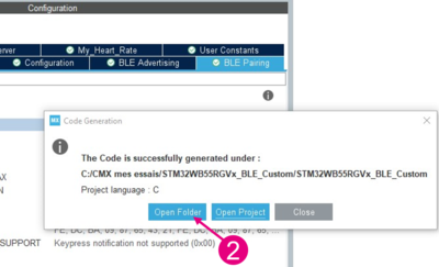
Once configuration is done in STM32CubeMX, the code can be generated ![]() :
:
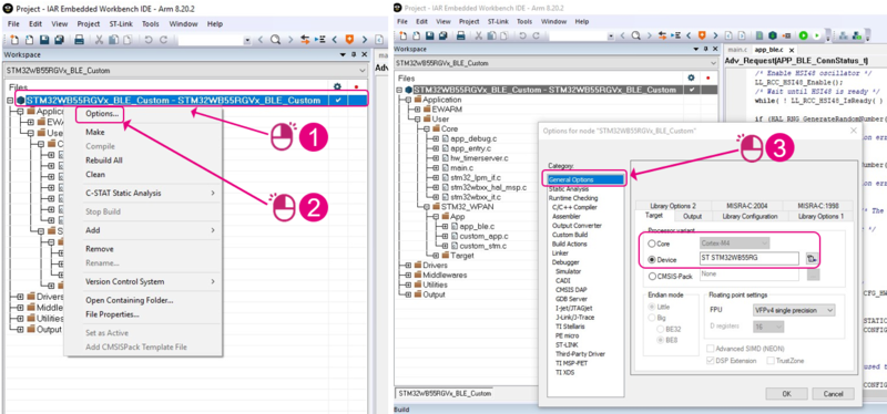
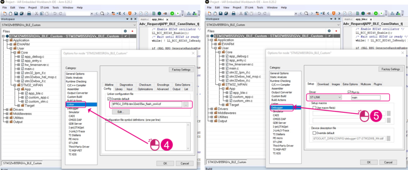
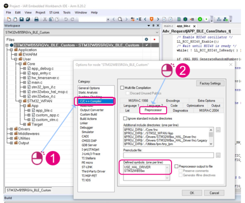
Open Project with IAR IDE, (\EWARM\ Project.eww) and ensure project options are correctly defined:
Project build from IAR IDE:
- Check there is no error when building the project from IAR.
- Connect the Nucleo board to the PC with USB cable.
- Flash the binary file into the P-NUCLEO-WB55[7] board.
- Run the application to make it advertise.
- Connect MyCST application thanks to ST BLE ToolBox application. Refer to ST BLE Toolbox Application chapter.
9. TeraTerm configuration
This chapter describes how to setup TeraTerm in order to display traces from the STM32WB projects.
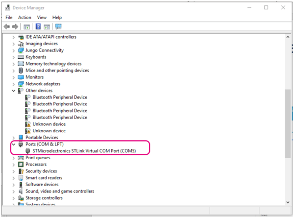
The ST-Link of the Nucleo board is displayed as a Virtual COM Port (as shown in the Device Manager window below).
USART1 pins are routed through this port, which is connected to serial terminal (TeraTerm) to display traces.
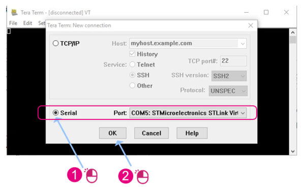
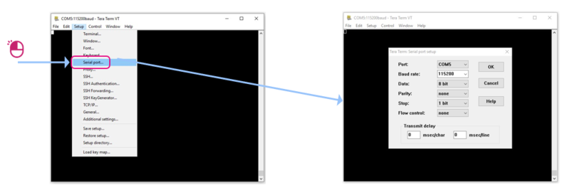
In TeraTerm interface, select the corresponding serial port:
Set the Serial Port configuration as follows:
Once the TeraTerm is configured and connected to the Nucleo board you can run your code and the enabled logs must be displayed.
10. ST BLE toolbox application
The following chapter describes ST BLE ToolBox application utilization.
10.1. Scan and connect
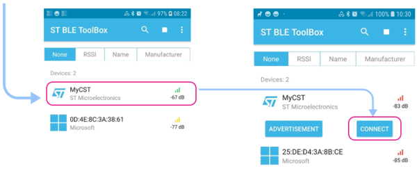
When you launch ST BLE ToolBox smartphone application, it scans to search WB devices. On the scan interface, the name (MyCST) of the application previously generated and build using STM32CubeMX and IAR must be displayed once discovered.
Select the application by clicking on his name, then click on Connect button:
10.2. Discover services and characteristics
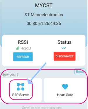
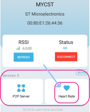
When connected to MyCST, scroll on services to find the defined ones.
- P2P Server Service:
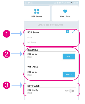
Tap P2P Server to display the associated characteristics:
As defined in STM32CubeMX we see P2P Server’s characteristics and associated properties:
- Heart Rate Service:
Tap Heart Rate to display the associated characteristics.
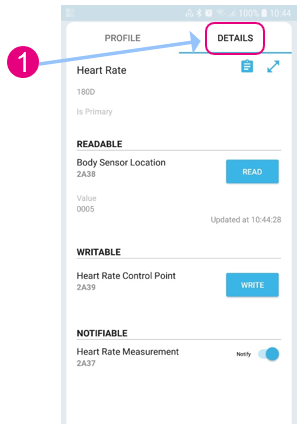
As defined in STM32CubeMX we see Heart Rate’s characteristics and associated properties (tap details ![]() ):
):
- Service Heart Rate : UUID = 0x180D
- Characteristic 1 : UUID = 0x2A37 is Notify
- Characteristic 3 : UUID = 0x2A38 is Readable
- Characteristic 2 : UUID = 0x2A39 is Writable
11. References
