1. Introduction
As the STM32WBA is based on an Arm® Cortex®-M33, it embeds the Arm® TrustZone® security feature.
TrustZone introduces hardware isolation allowing a developer to split its application between a Secure and a NonSecure part (sometimes referred to as Trusted and Nontrusted).
The basis of the isolation brought by TrustZone is to identify critical code & data (keys, private user data, etc.) and isolate it from the rest of the application which does not contain valuable assets.
The majority of the code (Application, Operating system, libraries) should run on the NonSecure side: if a vulnerability is found and exploited by an attacker, the malicious code executes in the NonSecure side, thus it is not able to break the isolation to access critical assets contained in the Secure side.
While it is technically possible to place a large amount of code in the Secure side, it is generally not recommended. The Secure side is designed to be a small, highly secure environment used to protect sensitive data and processes. Placing a large amount of code in the Secure side increases the attack surface and potentially introduces vulnerabilities that could be exploited by attackers.
For more information, see TrustZone for Cortex-M reference.[1]
2. Bluetooth® Low Energy
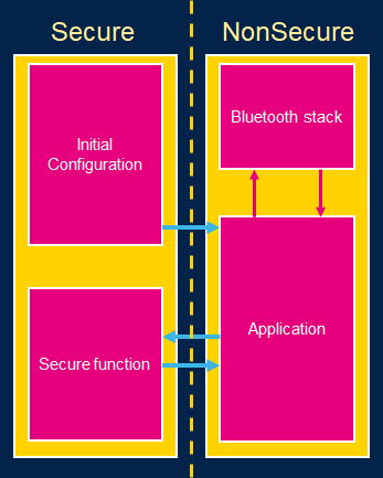
The Bluetooth® Low Energy (BLE) protocol is complex, therefore, a lot of code is written in order to establish the Bluetooth®LE protocol stack. Placing this stack in the Secure side of the STM32WBA breaks the principle of critical/noncritical isolation of the TrustZone.
That’s why, in our architecture, the Bluetooth® LE stack is placed in the NonSecure side.
As the Bluetooth® LE stack uses several cryptographical keys, these keys are also placed in the NonSecure side. These keys protect the application from an external attacker trying to eavesdrop on the Bluetooth® LE exchange or trying to conduct MITM (Man-in-the-Middle) attacks.
Regarding your application and the potential threats it may face, if one of those threats involves an attacker having the ability to remotely execute code, simply having the Bluetooth® LE keys stored in the non-secure area may not be sufficient to classify your application as secure. To ensure security, it is necessary to implement application-level encryption that utilizes keys isolated by the TrustZone architecture and managed by the Secure side.
| Example architecture |
|---|
3. Example
In order to build connected IoT devices with isolation properties leveraged by TrustZone, several configuration steps have to be followed to allow the Bluetooth® LE stack to run on the NonSecure side of the STM32WBA.
To illustrate such a configuration, the example BLE_p2pServer_TZ has been created.
This example is similar to BLE_p2pServer with TrustZone activated and the Blue LED connected to the Secure side of the MCU: The non-secure application runs the same application as the basic BLE_p2pServer. When a LED switch is required, the non-secure application calls a secure function in the Secure side. This secure function then handles the GPIO connected to the blue LED.
This example illustrates the following points:
- How to properly configure the STM32WBA when TrustZone is activated in order to run the Bluetooth® LE stack.
- How to connect a peripheral to the Secure side (here, the GPIO connected to the blue LED).
- How to make a secure function call (here, the secure function managing the LED).
4. Configuration
When using TrustZone, most of the STM32WBA subsystems (flash, RAM, peripherals, etc.) are attached to the Secure side. The MCU boots on the Secure side and configures some of the subsystems as non-secure for the non-secure application to use them.
This section describes how to configure a project using CubeMX in order to create a non-secure application using the Bluetooth® LE stack. To create the overall non-secure application as a CubeMX project, follow the dedicated page STM32WBA Bluetooth® Low Energy - STM32CubeMX Application Conception.
The main differences relative to the addition of TrustZone are described in this section.
4.1. Starting the CubeMX project
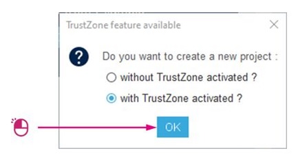
When creating a new project, TrustZone must be enabled first:
| TrustZone enabled |
|---|
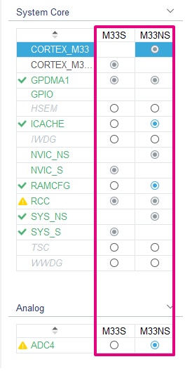
From here, you have the same panel described in the BLE_p2pServer page, but every section has a secure and/or non-secure configuration (M33S for the secure and M33NS for the non-secure):
| Security attribution example |
|---|
Some of the individual panels also have new configuration options relative to the Secure/NonSecure world. From here, it is possible to attach some of the MCU part to the Secure/NonSecure sides.
4.2. IP Configuration
When TrustZone security is activated by the TZEN option bit in the FLASH_OPTR, the default system security state is detailed below:
- CPU
– Cortex®-M33 is in the secure state after reset. The boot address must be at a secure address.
- Memory map
– SAU is fully secure after reset. Consequently, all memory map is fully secure. Up to eight SAU configurable regions are available for security attribution.
- Flash memory
– The flash memory security area is defined by watermark user options.
– Flash block-based security attributions are non-secure after reset.
- SRAMs
– All SRAMs are secure after reset. MPCBBx (block-based memory protection controller) are secure.
- Peripherals
– Securable peripherals are non-secure after reset.
– TrustZone-aware peripherals are non-secure after reset. Their secure configuration registers are secure.
– All GPIO are secure after reset
- Interrupts
– NVIC: All interrupts are secure after reset. NVIC is banked for secure and non-secure states.
– TZIC: All illegal access interrupts are disabled after reset.
This section describes how to properly configure these peripherals.
4.2.1. GTZC_S
The Global TrustZone Controller (GTZC) module configuration includes several submodules:
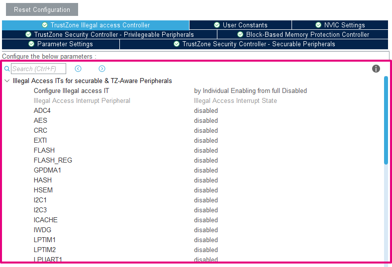
- TrustZone illegal access Controller (TZIC)
This module allows generating an illegal access interrupt (GTZC_IRQHandler) when an illegal access is detected on a peripheral. In our example, we leave it deactivated.
| TZIC configuration |
|---|
- TrustZone Security Controller (TZSC) – Privilegeable Peripherals
This module allows creating privileged/unprivileged access to peripherals. In our example, we do not use different privilege levels.
| TZSC configuration - Privilegeable Peripherals |
|---|
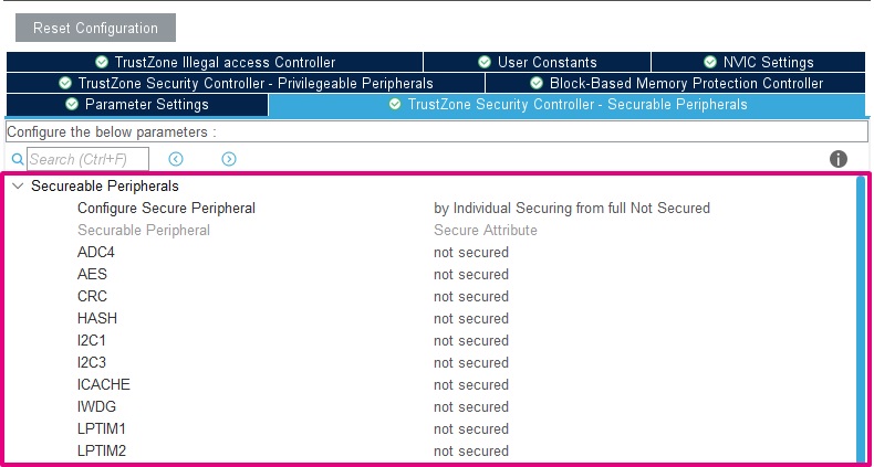
- TrustZone Security Controller (TZSC) – Securable Peripherals
This module allows attaching peripherals to the secure/non-secure context. In our example, apart from the GPIO, no peripherals are attached to the Secure side.
| TZSC configuration - Securable Peripherals |
|---|
- Block-Based Memory Protection Controller (MPCBB)
This module allows configuring part of the SRAM to the desired attribution (secure/non-secure & privileged/unprivileged). MPCBBx allows the configuration for SRAMx :
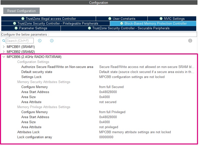
- As SRAM6 is used by the Bluetooth® LE IP (in the NonSecure side), it must be configured as non-secure and unprivileged with MPCBB6.
| MPCBB6 configuration |
|---|
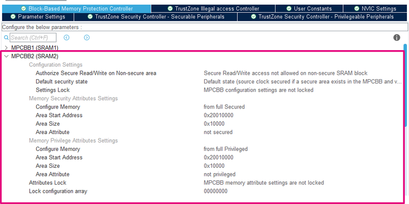
- As SRAM2 is used by the non-secure application, it must be configured as non-secure and unprivileged with MPCBB2.
| MPCBB2 configuration |
|---|
Other configurations of SRAM2 & SRAM1 are left to the user, depending on your application requirements.
4.2.2. GPDMA1
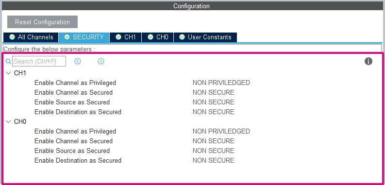
In the BLE_p2pServer_TZ example, the GPDMA1 is used by the UART logger.
With the addition of TrustZone, the peripheral parameters (channel, source & destination) can have a security attribution. In our example, as the logging is done on the NonSecure side, all of the DMA parameters have to be unprivileged and non-secure.
| GPDMA1 configuration |
|---|
4.2.3. GPIO
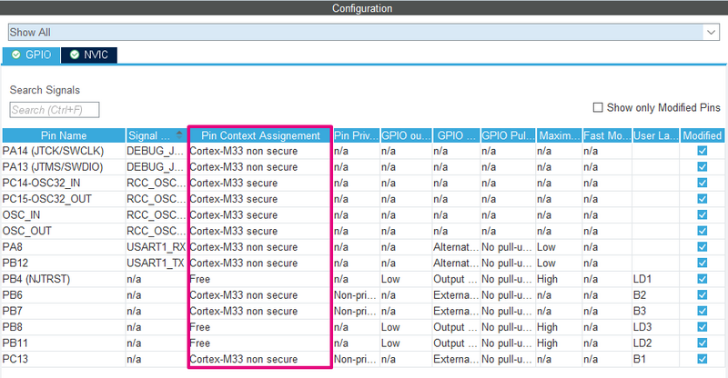
In the BLE_p2pServer_TZ project, the pin PB4 is connected to the Blue LED and controlled by the Secure side. This GPIO should be connected to the Secure side, and the other GPIOs connected to the NonSecure side.
| GPIO configuration |
|---|
4.2.4. RTC
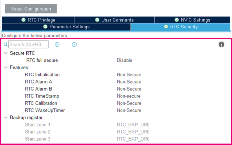
As the other peripherals, parts of the RTC can be defined to be accessed only by the Secure side. In our example we leave everything accessible by the NonSecure side.
| Interrupt configuration |
|---|
4.2.5. NVIC
There are three different kinds of interrupts:
- Banked the interrupt triggers in the current state context
- Secured the interrupt triggers in the Secure state context
- Configurable with the possibility to choose the security state in which the interrupt triggers
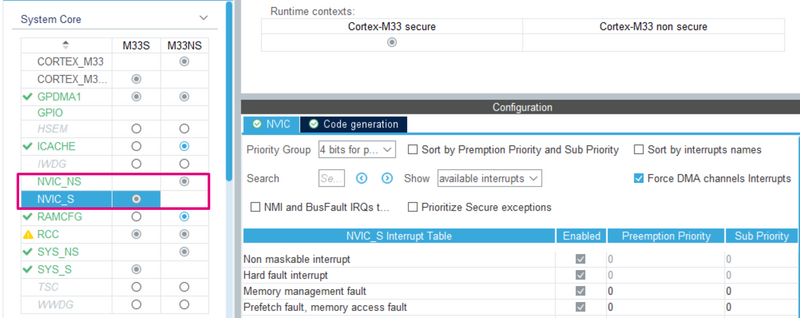
For the configurable interrupt, the register NVIC→ITNS manages its attribution. By correctly setting the attribution of your IRQ in the STM32CubeMX project, the right ITNS value is generated.
Once the correct security attribution has been set, it is possible to set the priority of the interrupt in the NVIC_S/NVIC_NS panel.
| Interrupt configuration |
|---|
4.2.6. SAU
The SAU (Secure Attribution Unit) configuration is created by default in the project, and it is not possible to configure it with CubeMX.
The SAU configuration is aligned with the secure and non-secure project linker file.
The basic project configuration is:
| Description | Region | Attribution |
|---|---|---|
| NonSecure code | 0x08080000 - 0x080FFFFF | Non-Secure |
| Bootloader, OTP, DESIG, Flash user options | 0x0BF88000 - 0x0BF97FFF | Non-Secure |
| NSC region | 0x0C07E000 - 0x0C07FFFF | Non-Secure Callable |
| NonSecure SRAM | 0x20010000 - 0x2001FFFF | Non-Secure |
| NonSecure Peripheral | 0x40000000 - 0x4FFFFFFF | Non-Secure |
This configuration is made in the function TZ_SAU_Setup in the file partition_stm32wba52xx.h.
4.2.7. Heap & Stack size
The Secure and NonSecure sides have their own stack and heap. It is possible to set them independently in the Project Manager panel:
| Heap and Stack configuration |
|---|
4.3. Secure Service creation
In our example, we create a function in the Secure side to manage the LED1, which is called by the NonSecure side. This type of function is called a Secure function which realizes a secure service.
As previously described, the goal of a secure service is to provide a secure and isolated execution environment within the device. This allows sensitive data and processes to be protected from unauthorized access or tampering by other software or hardware components in the system.
In our example, it is impossible for the NonSecure side to change the LED state without calling the Secure side. This example is simple, but a more complex service could be built to prevent the NonSecure side from accessing critical data while realizing the application for which it has been built. (Example: a secure service signing data from the NonSecure side while keeping the keys inside the Secure side)
The secure services are written in the file secure_nsc.c.
CMSE_NS_ENTRY void SECURE_LED_Blue_Off()
{
  HAL_GPIO_WritePin(GPIOB, GPIO_PIN_4, GPIO_PIN_SET);
}

CMSE_NS_ENTRY void SECURE_LED_Blue_On()
{
  HAL_GPIO_WritePin(GPIOB, GPIO_PIN_4, GPIO_PIN_RESET);
}
The attributes CMSE_NS_ENTRY tell the compiler that this function is callable from the NonSecure side (i.e. associated veneer and SG instructions are created).
5. Option Bytes Configuration
Once the correct configuration in the secure project is complete, in order to allow the secure project to boot and the NonSecure side to execute, some option bytes have to be correctly set.
- TrustZone enabling
| TZEN |
|---|
You must first "Apply" this option byte to have access to the next option bytes of this section.
- Secure Boot
The SECBOOTADD0 defines where the initial MSP value and Reset_Handler address are fetched for the secure project boot. It has to be correctly set according to our project linker file. In our example 0x0c000000.
| SECBOOTADD0 |
|---|
- Secure Watermark
The flash memory can be protected against non-secure read and write access. The secure flash region used in the project should be set as secure by the Secure Watermark registers and match the project linker file. In our example the range 0x08000000 - 0x0807ffff is dedicated to the Secure side.
| SECWM1 |
|---|
6. Booting Sequence
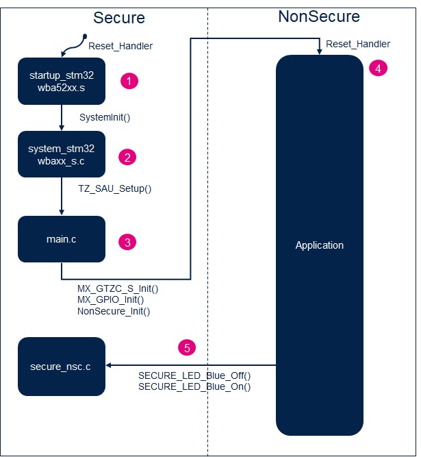
This section summarizes how the previously mentioned configuration is performed during the booting phase on a project generated by STM32CubeMX and how it is ordered.
| Overall booting sequence: |
|---|
7. How to Debug ?
As the whole example is split into two different subprojects (secure/ non-secure), the debugging of the example requires debugging the two projects at the same time.
7.1. IAR
With IAR, the right configuration is already present in the flash and debug of the two projects simultaneously.
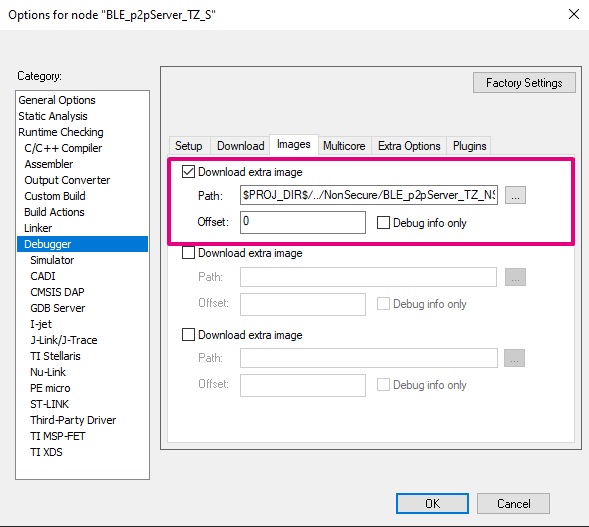
When selecting the secure project, in Options > Debugger > Images, the non-secure image is listed as an extra image.
When the debug and the flash of the secure project are complete from the IAR panel, the non-secure project is also flashed, and its symbols are loaded in case of debug.
| IAR - Extra Image Download |
|---|
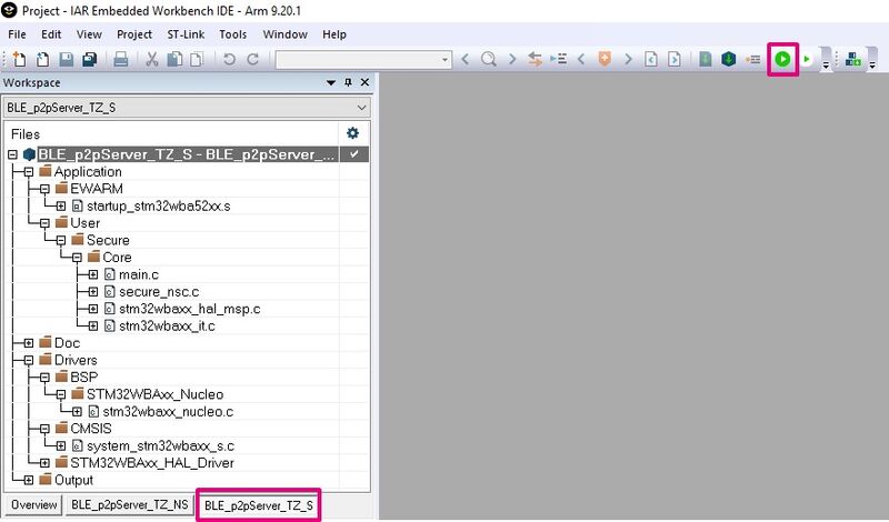
The secure project has to be compiled before the non-secure project. The Download & Debug of the secure project has to be used to correctly debug the entire example.
| IAR - Debug |
|---|
7.2. STM32CubeIDE
With STM32CubeIDE, the configuration of the flash and debug for the two projects has to be performed at the same time.
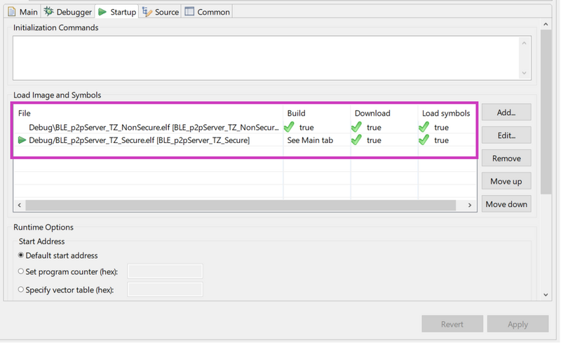
When selecting the secure project, in Debug as > Debug Configurations > startup, the non-secure project has to be added. Select "Add" and choose the non-secure project.
| STM32CubeIDE - Extra Image Download |
|---|
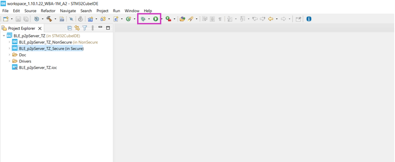
When the debug and the flash of the secure project are complete from the STM32CubeIDE panel, the non-secure project is also flashed, and its symbols are loaded in case of debug.
| STM32CubeIDE - Debug |
|---|
8. How to disable the TrustZone
Warning, if not done correctly, this step could brick your STM32WBA.
The option byte TZEN can only be disabled when doing an RDP regression from RDP1 to RDP0.
If the STM32WBA is already in RDP 2, as this RDP level is final and the option bytes are read-only, no RDP regression and TrustZone deactivation are possible.
As the debugger should be connected to modify the option byte TZEN and the RDP to 1 preventing a debugger to be connected to the Secure part, the debugger should be connected in "Hot plug" mode when the NonSecure part is booted.
You must be sure that a NonSecure part is booted by the Secure part before going in RDP 1. Two methods can be used to achieve this:
- Use your custom application or an example which successfully launches the NonSecure part.
- Use the bootloader with the PH3 pin. Note that a wrong nSWBOOT0, nBOOT0, BOOT_LOCK configuration could prevent this method from working.
Once this preliminary verification is complete, attach STM32CubeProgrammer in Hot plug mode and perform the following step to put TZEN to 0:
- If not in RDP 1, put the RDP to 1 and "Apply" the configuration.
- Once in RDP 1, put the RDP to 0 and uncheck the TZEN option byte and "Apply" the configuration in one shot.
The STM32WBA should have TrustZone disabled.
