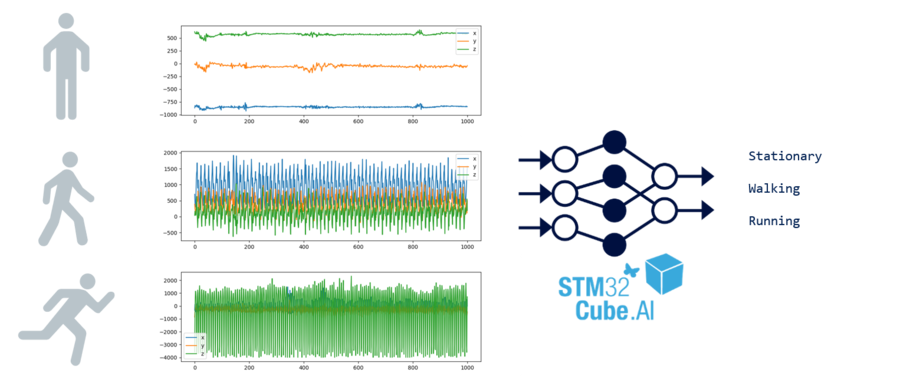
In this guide, you will learn how to create a motion sensing application to recognize human activities using machine learning on an STM32 microcontroller.
The model used classifies activities such as stationary, walking, or running from accelerometer data provided by the LSM6DSL sensor.
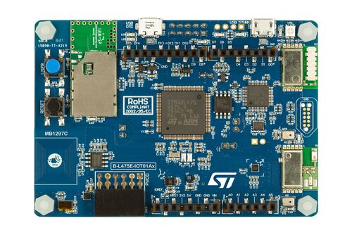
We will be creating a Human Activity Recognition (HAR) application for the STM32L4 Discovery kit IoT node B-L475E-IOT01A development board.
The board is powered by an STM32L475VG microcontroller (Arm® Cortex®-M4F MCU operating at 80 MHz with 1 Mbyte of Flash memory and 128 Kbytes of SRAM).
The following videos can also be used to follow along with this article:
- Part 1: https://www.youtube.com/watch?v=Djj2WMPgdsQ
- Part 2: https://www.youtube.com/watch?v=VznrX-Uyv3U
- Part 3: https://www.youtube.com/watch?v=dd6DdY4To9Q
1. What you will learn
- How to read motion sensor data.
- How to generate neural network code for STM32 using X-CUBE-AI.
- How to input sensor data into a neural network code.
- How to output inference results.
2. Requirements
- B-L475E-IOT01A: STM32L4 Discovery kit IoT node.
- STM32CubeIDE (v1.6.1 or later) with:
- X-CUBE-MEMS1 (v8.3.0 or later) - for motion sensor component drivers.
- X-CUBE-AI (v7.0.0 or later) - for the neural network conversion tool & network runtime library.
- Note: X-CUBE-AI and X-CUBE-MEMS1 installation is not going to be covered in this tutorial. Installation instructions can be found in UM1718 - Section 3.4.4 Installing embedded software packs).
- A serial terminal application (such as Tera Term, PuTTY, GNU Screen or others).
- A Keras model. You can either download the pre-trained model.h5 or create your own model using your own data captures.
3. Create a new project
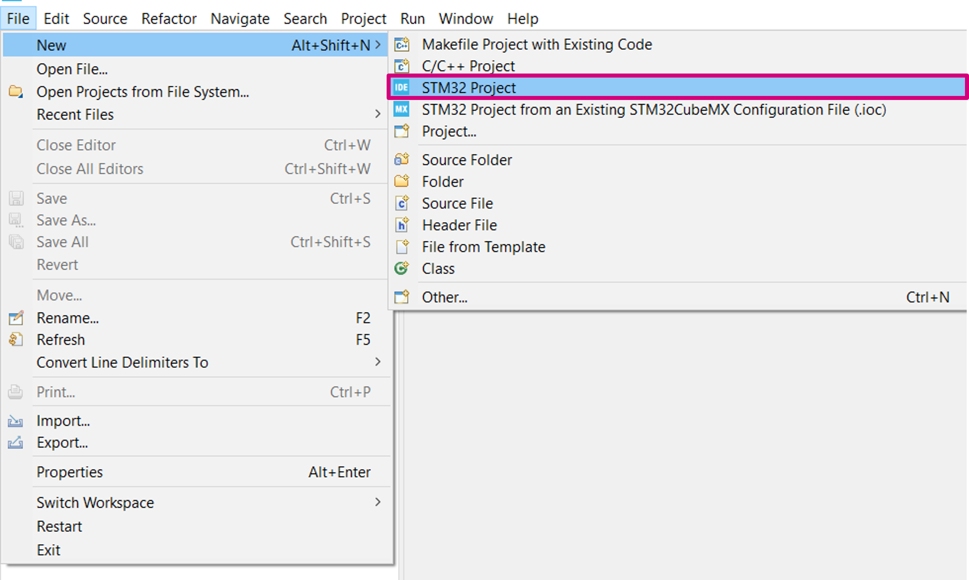
Create a new STM32 project: File > New > STM32 Project.
3.1. Select your board
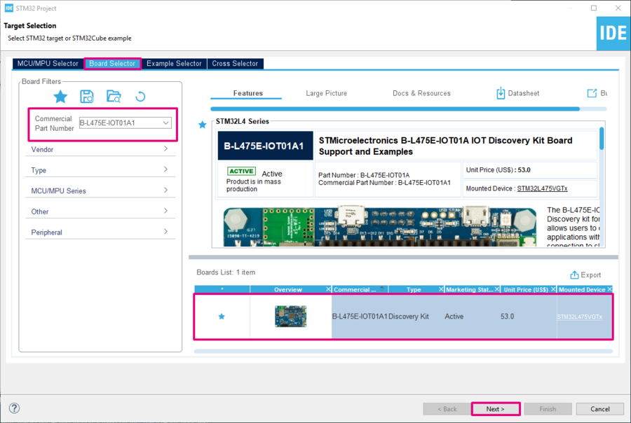
- Open the Board Selector tab.
- Search for B-L475E-IOT01A1.
- Select the board in the bottom-right board list table.
- Click on Next to configure the project name, and location.
- When prompted to initialize all peripherals with their default mode, select No to avoid generating unused code.
3.2. Add the LSM6DSL sensor driver from X-CUBE-MEMS Components
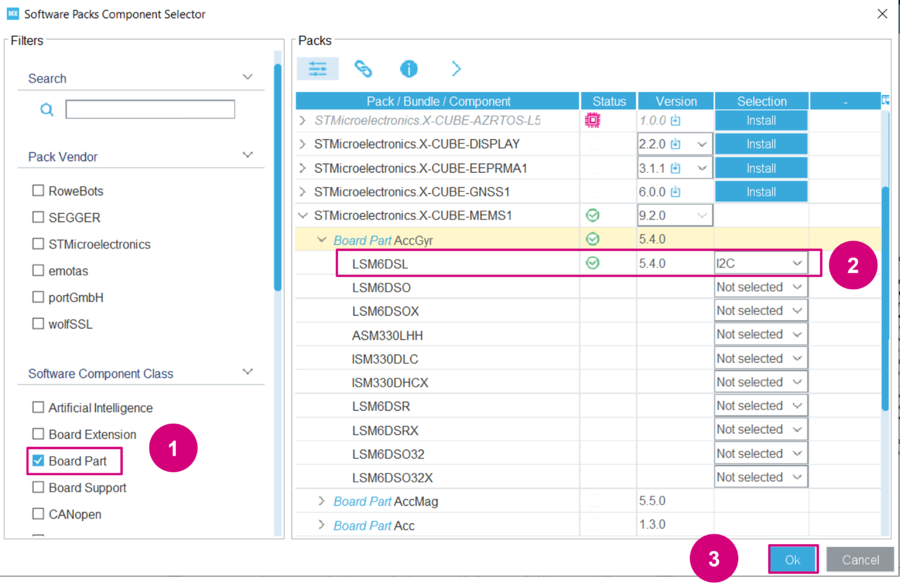
Open the Software Packs Component Selector: Software Packs > Select Components.
- In the Pinout & Configuration tab, click on Software Packs > Select Components.
Select the LSM6DSL intertial module with an I2C interface.
- Apply the Board Part filter.
- Under the STMicroelectronics.X-CUBE-MEMS1 bundle, select Board Part > AccGyr / LSM6DSL I2C and click on OK.
3.3. Configure the I2C bus interface
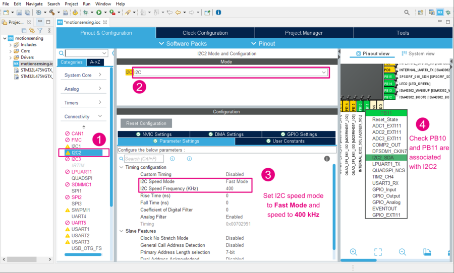
- Back in STM32CubeMX, choose the I2C2 Connectivity interface.
- Enable the I2C bus interface by choosing mode I2C.
- Set the I2C mode to Fast Mode and speed to 400 kHz (LSM6DSL maximum I2C clock frequency)
- Under the GPIO settings tab, associate the PB10 and PB11 pins with the I2C2 interface.
3.4. Configure the LSM6DSL interrupt line
To receive INT1 signals from the LSM6DSL sensor, check your MCU GPIO pin is correctly configured to receive external interrupts on PD11.
- In the GPIO settings (under System Core), set PD11 to External Interrupt Mode with Rising edge trigger detection (EXTI_RISING)
- In the NVIC settings (under System Core), enable EXTI line[15:10] interrupts for EXTI11 interrupt.
3.5. Configure X-CUBE-MEMS1
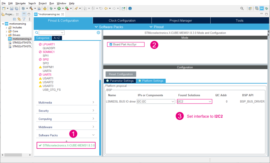
- Expand Software Packs to select STMicroelectronics.X-CUBE-MEMS1.8.3.0.
- Enable Board Part AccGyr.
- Configure the Platform settings with I2C2 from the dropdown menu.
3.6. Configure the UART communication interface
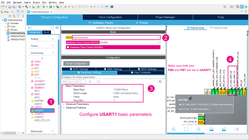
Configure the USART1 interface in asynchronous mode and with the default parameters (115200 bauds, 8-bit, no parity and 1 stop bit). You can also check the GPIO settings to view the associated USART1 GPIO. PB6 and PB7 should be configured as Alternate Function Push-Pull.
- Select the USART1 Connectivity interface.
- Enable Asynchronous mode.
- If not already configured, set the Baud Rate to 115200 bit/s.
- In the Pinout view or under the GPIO Settings tab, ensure PB6 and PB7 are associated with USART1.
3.7. Generate code
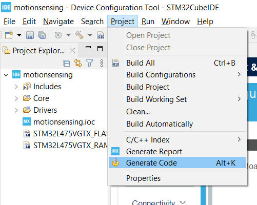
The MCU configuration is now complete and you can generate code either by saving saving your project or Project > Generate Code.
4. Bootstrap the code in main.c
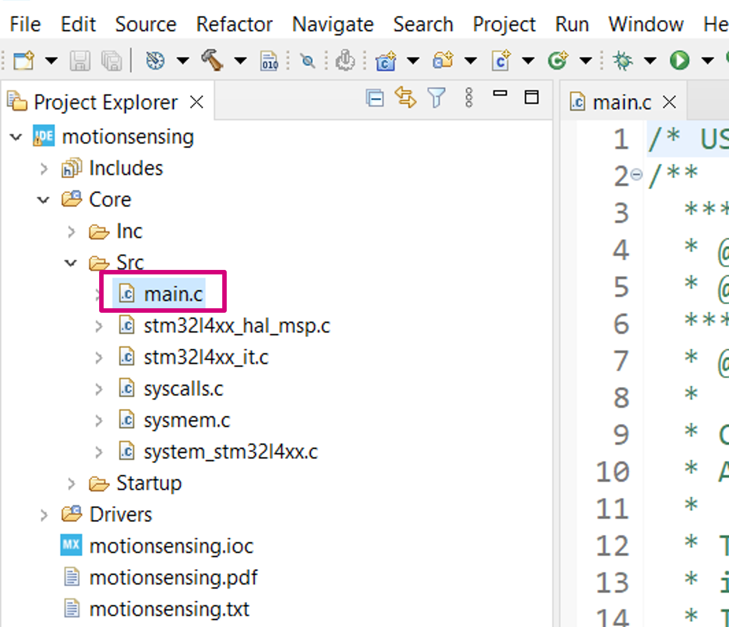
4.1. Open main.c
In the Project Explorer pane, double-click on Core/Src/main.c to open the code editor for the user application code.
4.2. Include headers for the LSM6DSL sensor
Add the LSM6DSL driver, the I2C bus header files. stdio is also included because we are going to use printf outputs.
/* Private includes ----------------------------------------------------------*/
/* USER CODE BEGIN Includes */
#include "lsm6dsl.h"
#include "b_l475e_iot01a1_bus.h"
#include <stdio.h>
/* USER CODE END Includes */
4.3. Create a global LSM6DSL motion sensor instance and data available status flag
The variable is marked as volatile because it is going to be modified by an interrupt service routine:
/* Private variables ---------------------------------------------------------*/
UART_HandleTypeDef huart1;

/* USER CODE BEGIN PV */
LSM6DSL_Object_t MotionSensor;
volatile uint32_t dataRdyIntReceived;
/* USER CODE END PV */
4.4. Define the MEMS_Init() function to configure the LSM6DSL motion sensor
Add a MEMS_Init() function declaration:
/* USER CODE BEGIN PFP */
static void MEMS_Init(void);
/* USER CODE END PFP */
Use the following sequence to configure the LSM6DSL sensor to:
- Range: ±4 g
- Output Data Rate (ODR): 26 Hz
- Linear acceleration sensitivity: 0.122 mg/LSB (FS = ±4)
- Resolution: 16 bits (little endian by default)
/* USER CODE BEGIN 4 */
static void MEMS_Init(void)
{
  LSM6DSL_IO_t io_ctx;
  uint8_t id;
  LSM6DSL_AxesRaw_t axes;

  /* Link I2C functions to the LSM6DSL driver */
  io_ctx.BusType     = LSM6DSL_I2C_BUS;
  io_ctx.Address     = LSM6DSL_I2C_ADD_L;
  io_ctx.Init        = BSP_I2C2_Init;
  io_ctx.DeInit      = BSP_I2C2_DeInit;
  io_ctx.ReadReg     = BSP_I2C2_ReadReg;
  io_ctx.WriteReg    = BSP_I2C2_WriteReg;
  io_ctx.GetTick     = BSP_GetTick;
  LSM6DSL_RegisterBusIO(&MotionSensor, &io_ctx);

  /* Read the LSM6DSL WHO_AM_I register */
  LSM6DSL_ReadID(&MotionSensor, &id);
  if (id != LSM6DSL_ID) {
    Error_Handler();
  }

  /* Initialize the LSM6DSL sensor */
  LSM6DSL_Init(&MotionSensor);

  /* Configure the LSM6DSL accelerometer (ODR, scale and interrupt) */
  LSM6DSL_ACC_SetOutputDataRate(&MotionSensor, 26.0f); /* 26 Hz */
  LSM6DSL_ACC_SetFullScale(&MotionSensor, 4);          /* [-4000mg; +4000mg] */
  LSM6DSL_ACC_Set_INT1_DRDY(&MotionSensor, ENABLE);    /* Enable DRDY */
  LSM6DSL_ACC_GetAxesRaw(&MotionSensor, &axes);        /* Clear DRDY */

  /* Start the LSM6DSL accelerometer */
  LSM6DSL_ACC_Enable(&MotionSensor);
}
/* USER CODE END 4 */
Info: For code simplicity and readability, status code return value checking has been omitted. It is strongly advised to check if the return status is equal to LSM6DSL_OK.
4.5. Add a callback to the LSM6DSL sensor interrupt line (INT1 signal on GPIO PD11)
It is used to set the dataRdyIntReceived status flag when a new set of measurement data is available to be read:
/* USER CODE BEGIN 4 */
/*...*/

void HAL_GPIO_EXTI_Callback(uint16_t GPIO_Pin)
{
  if (GPIO_Pin == GPIO_PIN_11) {
    dataRdyIntReceived++;
  }
}
/* USER CODE END 4 */
4.6. Retarget printf to a UART serial port
Retarget the printf output to the serial UART interface. Insert the following code snippet if you are working with a GCC toolchain:
/*...*/

int _write(int fd, char * ptr, int len)
{
  HAL_UART_Transmit(&huart1, (uint8_t *) ptr, len, HAL_MAX_DELAY);
  return len;
}
/* USER CODE END 4 */
Info: stdout redirection is toolchain dependent. Example implementations for other compilers can be found in aiSystemPerformance.c from the SystemPerformance application.
4.7. Implement an Error_Handler()
To protect your application of any potential issues, it is recommended to implement a trapping mechanism in the the Error_Handler() function.
- Create an infinite
whileloop to trap errors and blink the board’s LED.
void Error_Handler(void)
{
  /* USER CODE BEGIN Error_Handler_Debug */
  while(1) {
    HAL_GPIO_TogglePin(LED2_GPIO_Port, LED2_Pin);
    HAL_Delay(50); /* wait 50 ms */
  }
  /* USER CODE END Error_Handler_Debug */
}
5. Read accelerometer data
5.1. Call the previously implemented MEMS_Init() function
int main(void)
{
  /* ... */

  /* USER CODE BEGIN 2 */

  dataRdyIntReceived = 0;
  MEMS_Init();

  /* USER CODE END 2 */
5.2. Add code to read acceleration data
int main(void)
{
  /* ... */

  /* Infinite loop */
  /* USER CODE BEGIN WHILE */
  while (1)
  {
    if (dataRdyIntReceived != 0) {
      dataRdyIntReceived = 0;
      LSM6DSL_Axes_t acc_axes;
      LSM6DSL_ACC_GetAxes(&MotionSensor, &acc_axes);
      printf("% 5d, % 5d, % 5d\r\n",  (int) acc_axes.x, (int) acc_axes.y, (int) acc_axes.z);
    }
    /* USER CODE END WHILE */

    /* USER CODE BEGIN 3 */
  }
  /* USER CODE END 3 */
}
5.3. Compile, download and run
- Build your project: Project > Build All
- Run > Run As > 1 STM32 Cortex-M C/C++ Application. Then click Run.
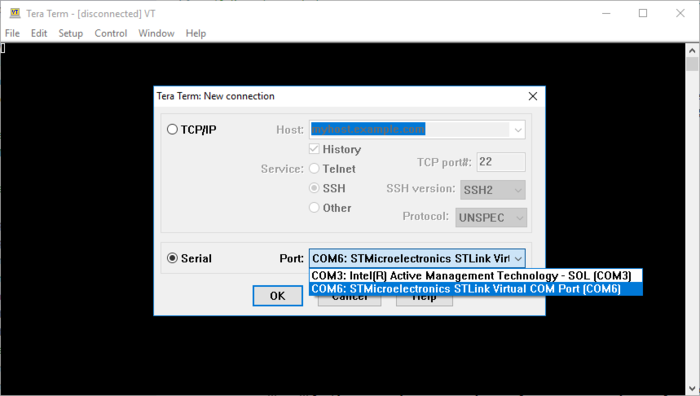
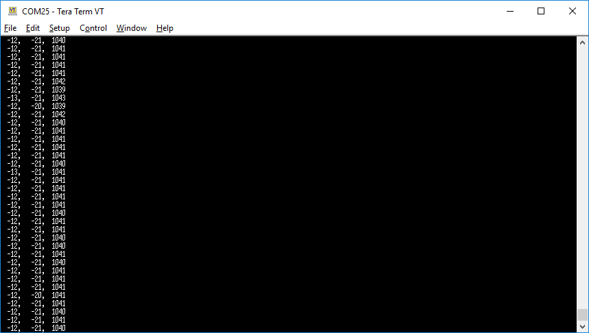
- Open a serial monitor application (such as Tera Term, PuTTY or GNU Screen) and connect to the ST-LINK Virtual COM port (COM port number may differ on your machine).
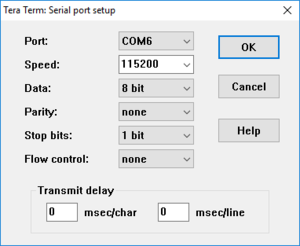
- Configure the communication settings to 115200 baud, 8-bit, no parity.
5.4. Visualize and capture live sensor data
When running your application, a new set of 24 acceleration axis values (x, y, z) should be displayed in the serial output every 1/26 Hz = 38 ms. When the board is sitting upright on your desk (not moving), x, y values should be close to 0 g and z should be close to 1 g (1000 mg).
- To capture data, you can copy paste the serial output into a
.csvtext file or use the following command on a Linux machine:
$ cat /dev/ttyXXXX > capture.csv
With every new capture, you can plot the data using matplotib or any other tool capable of reading csv data. Below is an example of a simple python script to plot (x, y, z data captures):
# plotter.py
# Copyright (c) STMicroelectronics
# License: BSD-3-Clause
import argparse
import numpy as np
import matplotlib.pyplot as plt

parser = argparse.ArgumentParser()
parser.add_argument('filename')
args = parser.parse_args()

data = np.loadtxt(args.filename, delimiter=',')

plt.figure(figsize=(10, 3))
plt.plot(data[:, 0], label='x')
plt.plot(data[:, 1], label='y')
plt.plot(data[:, 2], label='z')
plt.legend()
plt.show()
- You can then visualize the captured data using with the following command:
$ python plotter.py capture.csv
If desired, the .csv file can be manually edited for cleanup using a text editor for example. Once you are satisfied with you captures, they can be used for a machine learning model training.
6. Create an STM32Cube.AI application using X-CUBE-AI
6.1. Create your model
For this example, we will be using a Keras model trained using a small dataset created specifically for this example. Either download the pre-trained model.h5 or create your own model using your own data captures.
- Instructions on how to create and train your own model can be found in the following Python Notebook: https://colab.research.google.com/github/STMicroelectronics/stm32ai/blob/master/AI_resources/HAR/Human_Activity_Recognition.ipynb
- dataset.zip Is a ready-to-use dataset of 3-axis acceleration data for various human activities.
| File:Info.png | The model will be using unprocessed data. For increased accuracy, data preprocessing such as gravity rotation and suppression can be added. This requires a model re-training to include the data preprocessing. Data preprocessing usage and alternative models can be found in FP-AI-SENSING1. If using a different model, make sure to adjust sensor settings (data rate and scale) accordingly to match the training dataset. |
6.2. Add STM32Cube.AI to your project
Back into STM32CubeIDE, got back to the Software Components selection:
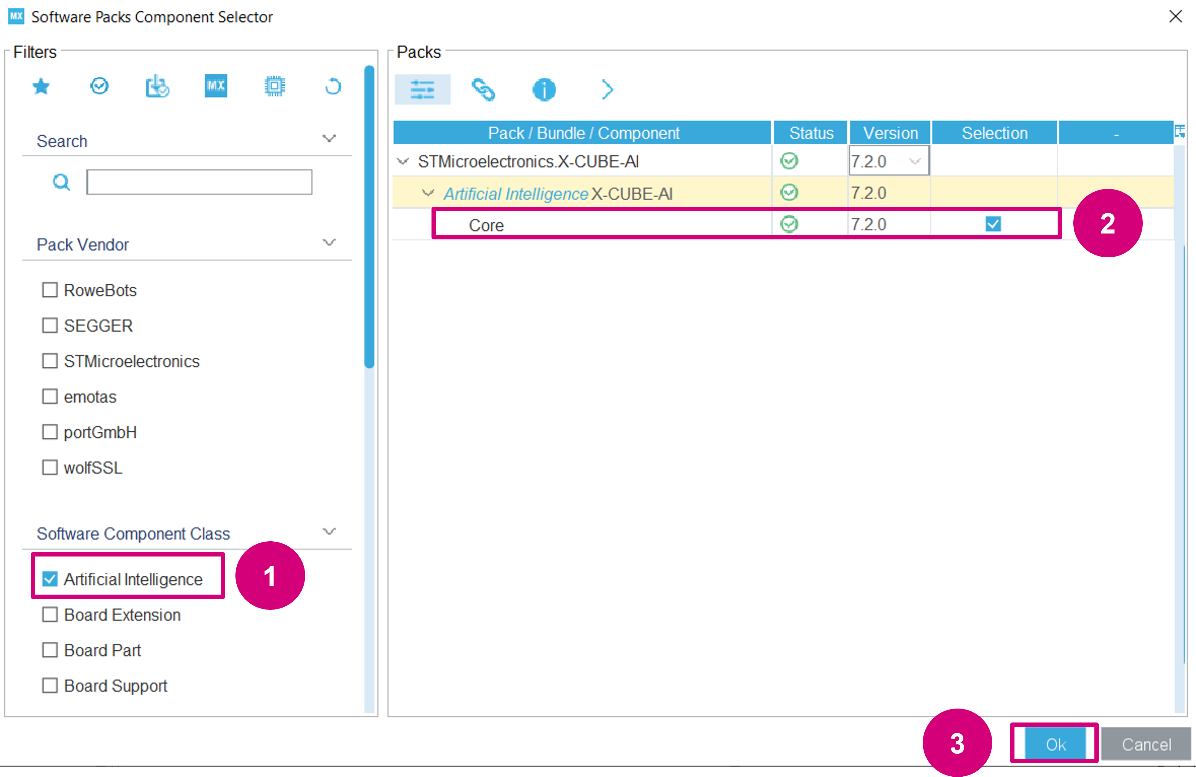
Add the X-CUBE-AI Core component to include the library and code generation options:
- Use the Artificial Intelligence filter.
- Enable Core.
- Click OK.
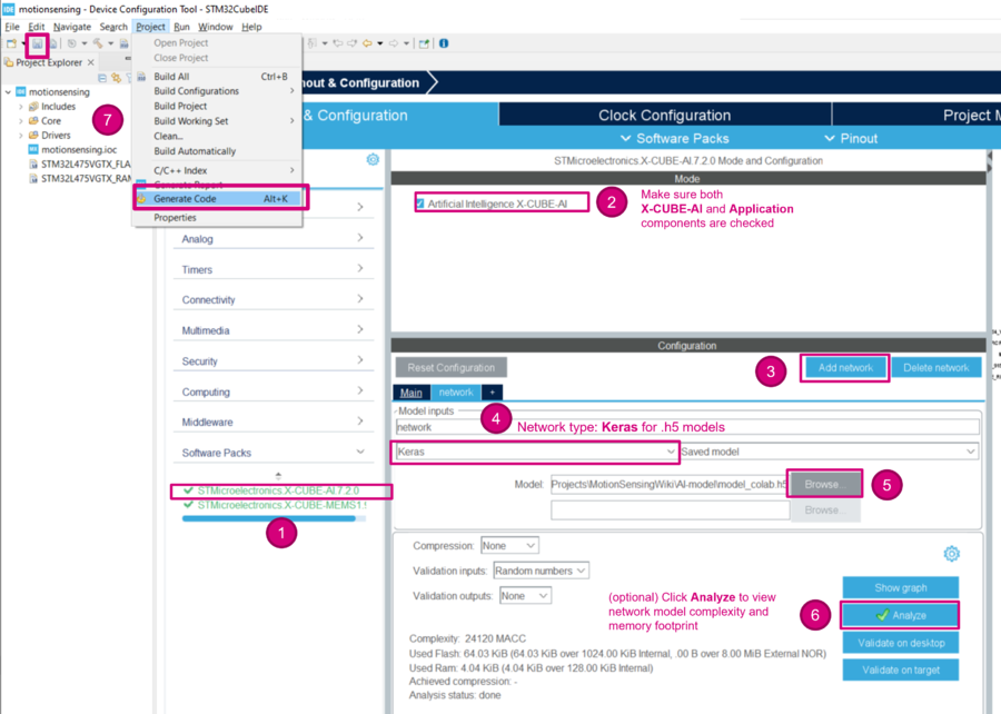
Next, configure the X-CUBE-AI component to use your keras model:
- Expand Additional Software to select STMicroelectronics.X-CUBE-AI.7.0.0
- Check to make sure the X-CUBE-AI component is selected
- Click Add network
- Change the Network Type to Keras
- Browse to select the model
- (optional) Click on Analyze to view the model memory footprint, occupation and complexity.
- Save or Project > Generate Code
| File:Info.png | For complex models, it is recommended to increase the application stack size. Stack size usage can be found using the X-CUBE-AI System Performance application component. |
6.3. Include headers for STM32Cube.AI
Add both the Cube.AI runtime interface header file (ai_platform.h) and model-specific header files generated by Cube.AI (network.h and network_data.h).
/* Private includes ----------------------------------------------------------*/
/* USER CODE BEGIN Includes */
#include "lsm6dsl.h"
#include "b_l475e_iot01a1_bus.h"
#include "ai_platform.h"
#include "network.h"
#include "network_data.h"
#include <stdio.h>
/* USER CODE END Includes */
6.4. Declare neural-network buffers
With default generation options, three additional buffers should be allocated: the activations, input and output buffers.
The activations buffer is private memory space for the CubeAI runtime. During the execution of the inference, it is used to store intermediate results.
Declare a neural-network input and output buffer (aiInData and aiOutData). The corresponding output labels must also be added to activities.
/* USER CODE BEGIN PV */
LSM6DSL_Object_t MotionSensor;
volatile uint32_t dataRdyIntReceived;
ai_handle network;
float aiInData[AI_NETWORK_IN_1_SIZE];
float aiOutData[AI_NETWORK_OUT_1_SIZE];
uint8_t activations[AI_NETWORK_DATA_ACTIVATIONS_SIZE];
const char* activities[AI_NETWORK_OUT_1_SIZE] = {
  "stationary", "walking", "running"
};
/* USER CODE END PV */
6.5. Add AI bootstrapping functions
In the list of function prototypes, add the following declarations:
/* Private function prototypes -----------------------------------------------*/
void SystemClock_Config(void);
static void MX_GPIO_Init(void);
static void MX_USART1_UART_Init(void);
static void MX_CRC_Init(void);
/* USER CODE BEGIN PFP */
static void MEMS_Init(void);
static void AI_Init(ai_handle w_addr, ai_handle act_addr);
static void AI_Run(float *pIn, float *pOut);
static uint32_t argmax(const float * values, uint32_t len);
/* USER CODE END PFP */
And add the following code snippets to use the STM32Cube.AI library for models with float32 inputs.
static void AI_Init(ai_handle w_addr, ai_handle act_addr)
{
ai_error err;
/* 1 - Create an instance of the model */
err = ai_network_create(&network, AI_NETWORK_DATA_CONFIG);
if (err.type != AI_ERROR_NONE) {
printf("ai_network_create error - type=%d code=%d\r\n", err.type, err.code);
Error_Handler();
}
/* 2 - Initialize the instance */
const ai_network_params params = AI_NETWORK_PARAMS_INIT(
AI_NETWORK_DATA_WEIGHTS(w_addr),
AI_NETWORK_DATA_ACTIVATIONS(act_addr)
);
if (!ai_network_init(network, ¶ms)) {
err = ai_network_get_error(network);
printf("ai_network_init error - type=%d code=%d\r\n", err.type, err.code);
Error_Handler();
}
}
static void AI_Run(float *pIn, float *pOut)
{
  ai_i32 batch;
  ai_error err;

  /* 1 - Create the AI buffer IO handlers with the default definition */
  ai_buffer ai_input[AI_NETWORK_IN_NUM] = AI_NETWORK_IN;
  ai_buffer ai_output[AI_NETWORK_OUT_NUM] = AI_NETWORK_OUT;

  /* 2 - Update IO handlers with the data payload */
  ai_input[0].n_batches = 1;
  ai_input[0].data = AI_HANDLE_PTR(pIn);
  ai_output[0].n_batches = 1;
  ai_output[0].data = AI_HANDLE_PTR(pOut);

  batch = ai_network_run(network, ai_input, ai_output);
  if (batch != 1) {
    err = ai_network_get_error(network);
    printf("AI ai_network_run error - type=%d code=%d\r\n", err.type, err.code);
    Error_Handler();
  }
}
6.6. Create an argmax function
Create an argmax function to return the index of the highest scored output.
static uint32_t argmax(const float * values, uint32_t len)
{
  float max_value = values[0];
  uint32_t max_index = 0;
  for (uint32_t i = 1; i < len; i++) {
    if (values[i] > max_value) {
      max_value = values[i];
      max_index = i;
    }
  }
  return max_index;
}
6.7. Call the previously implemented AI_Init() function
int main(void)
{
  /* ... */

  /* USER CODE BEGIN 2 */

  dataRdyIntReceived = 0;
  MEMS_Init();
  AI_Init(ai_network_data_weights_get(), activations);

  /* USER CODE END 2 */
6.8. Update the main while loop
Finally, put everything together with the following changes in your main while loop:
  /* Infinite loop */
  /* USER CODE BEGIN WHILE */
  uint32_t write_index = 0;
  while (1)
  {
    if (dataRdyIntReceived != 0) {
      dataRdyIntReceived = 0;
      LSM6DSL_Axes_t acc_axes;
      LSM6DSL_ACC_GetAxes(&MotionSensor, &acc_axes);
      // printf("% 5d, % 5d, % 5d\r\n",  (int) acc_axes.x, (int) acc_axes.y, (int) acc_axes.z);

      /* Normalize data to [-1; 1] and accumulate into input buffer */
      /* Note: window overlapping can be managed here */
      aiInData[write_index + 0] = (float) acc_axes.x / 4000.0f;
      aiInData[write_index + 1] = (float) acc_axes.y / 4000.0f;
      aiInData[write_index + 2] = (float) acc_axes.z / 4000.0f;
      write_index += 3;

      if (write_index == AI_NETWORK_IN_1_SIZE) {
        write_index = 0;

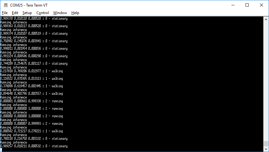
        printf("Running inference\r\n");
        AI_Run(aiInData, aiOutData);

        /* Output results */
        for (uint32_t i = 0; i < AI_NETWORK_OUT_1_SIZE; i++) {
          printf("%8.6f ", aiOutData[i]);
        }
        uint32_t class = argmax(aiOutData, AI_NETWORK_OUT_1_SIZE);
        printf(": %d - %s\r\n", (int) class, activities[class]);
      }
    }
    /* USER CODE END WHILE */

    /* USER CODE BEGIN 3 */
  }
  /* USER CODE END 3 */
}
6.9. Enable float with printf in the build settings
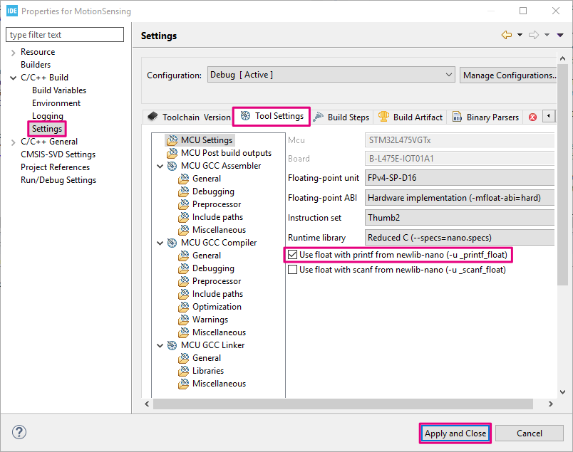
When using GCC and Newlib-nano, formatted input/output of floating-point number are implemented as weak symbol. If you want to use %f, you have to pull in the symbol by explicitly specifying -u _printf_float command option in the GCC Linker flags. This option can be added to the project build settings:
- Open the project properties in Project > Properties.
- Expand C/++ Build and go to Settings.
- Under the Tool Settings tab, enable Use float with printf from newlib-nano (-u _printf_float).
6.10. Compile, download and run
You can now compile, download and run your project to test the application using live sensor data. Try to move the board around at different speeds to simulate human activities.
- At idle, when the board is at rest, the serial output should display “stationary”.
- If you move the board up and down slowly to moderately fast, the serial output should display “walking”.
- If you shake the board quickly, the serial output should display “running”.
7. Real-time scheduling considerations
In order to provide real-time results and allow the STM32 application to read accelerometer data without interrupting the model inference, all tasks inside the main while loop should be able to execute under 38 ms (1/26 Hz). For example, we can have the following scheduling breakdown on the STM32L4 @ 80 MHz:
- 0.33 ms - Sensor data acquisition over I2C (3x2 bytes of data (16-bit x, y, z values) + 1 byte for sensitivity read).
- 4 ms - Sensor data output UART printf (40 bytes; 3-axis values in ASCII)
- < 0.1 ms - Preprocessing (data normalization)
- AI model inference time:
- ~6 ms for the provided model.h5 (used here)
- ~4 ms for the IGN_WSDM model
- ~11 ms for the GMP model
- 4 ms - Output inference results over UART(40 bytes in ASCII)
| File:Info.png | To provide more breathing space for time consuming task such as running a neural network inference and blocking serial output messages using printf, the LSM6DSL sensor can be configured to use its internal FIFO to accumulate accelerometer data capture and wake-up the MCU once all required acceleration values have been captured for the model inference. The FIFO threshold size can be adjusted to the neural network model input size. |
| File:Info.png | Inference time and memory footprint can also be reduced when using a quantized model. |
7.1. Overrun protection
If you want to guarantee real-time execution of your model and application, you can add sensor reading overrun detection by changing the LSM6DSL Data-Ready interrupt signal to pulse even if it values have not yet been read. The dataRdyIntReceived counter will be incremented each time the STM32 sees a a pulse from the sensor; even if the main thread is locked in a time consuming task. The counter can then be check ed prior to each data read to make sure there has not been more than one pulse since the last reading.
- Change the sensor initialization routine to configure DRDY INT1 signal in pulse mode:
static void MEMS_Init(void)
{
  /* ... */

  /* Configure the LSM6DSL accelerometer (ODR, scale and interrupt) */
  LSM6DSL_ACC_SetOutputDataRate(&MotionSensor, 26.0f); /* 26 Hz */
  LSM6DSL_ACC_SetFullScale(&MotionSensor, 4);          /* [-4000mg; +4000mg] */
  LSM6DSL_Set_DRDY_Mode(&MotionSensor, 1);             /* DRDY pulsed mode */
  LSM6DSL_ACC_Set_INT1_DRDY(&MotionSensor, ENABLE);    /* Enable DRDY */
  LSM6DSL_ACC_GetAxesRaw(&MotionSensor, &axes);        /* Clear DRDY */

  /* Start the LSM6DSL accelerometer */
  LSM6DSL_ACC_Enable(&MotionSensor);
}
- And check that there has not been more than one DRDY pulse since the last sensor reading:
  while (1)
  {

    if (dataRdyIntReceived != 0) {
      if (dataRdyIntReceived != 1) {
        printf("Overrun error: new data available before reading previous data.\r\n");
        Error_Handler();
      }
      LSM6DSL_Axes_t acc_axes;
      LSM6DSL_ACC_GetAxes(&MotionSensor, &acc_axes);
      dataRdyIntReceived = 0;

      /* ... */

    }
  }
If you don't get any errors, your are good to go. Otherwise, you might want to use a smaller model, limit the number of printf or even consider some other approach like the usage of a FIFO or an RTOS for example. To check that your overrun capture is working correctly, you can try adding a simple HAL_Delay() to trigger an overrun error.
8. Closing thoughts
Now that you have seen how to capture and record data, you can:
- create additional data captures to increase the dataset robustness against model over fitting. It is a good idea to vary the sensor position and user.
- capture new classes of activities (such as cycling, automotive, skiing and others) to enrich the dataset.
- experiment with different model architectures for other use-cases.
The boards offers many other sensing and connectivity options:
- MEMS microphones: for audio and voice applications
- Other motion sensors (gyroscope, magnetometer)
- Environmental sensors (temperature & humidity)
- VL53L0X Time-of-Flight (ToF) proximity sensor
- Connectivity (Bluetooth® Low Energy, Wi-Fi® and Sub-GHz)
- ARDUINO® and Pmod™ connectors
9. References
- FP-AI-SENSING1
- Shahnawax/HAR-CNN-Keras: Human Activity Recognition Using Convolutional Neural Network in Keras
- How to Develop 1D Convolutional Neural Network Models for Human Activity Recognition
- Human Activity Recognition (HAR) Tutorial with Keras and Core ML
