1. Bluetooth® Low Energy power consumption profile
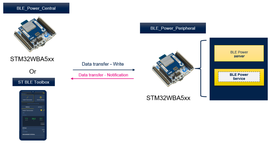
The Bluetooth® Low Energy power consumption profile is a generic attribute profile (GATT) based low-energy profile defined by STMicroelectronics with proprietary UUIDs. Provided in both applications BLE_Power_Peripheral and BLE_Power_Central on STM32WBA products[1] offering users fully flexible applications for power measurement purposes.
- The Bluetooth® Low Energy power peripheral
- In Advertising state: Used to measure power consumption with different possible configurations (Advertising type, advertising interval,…)
- In Connected state: Used to measure power consumption in connected idle or with data transfer.
- The Bluetooth® Low Energy power central
- In Connected state: Used to measure power consumption in connected idle or with data transfer.
Both applications are available under STM32CubeWBA firmware package [2]
| Bluetooth® Low Energy power profile & STM32WBA |
|---|
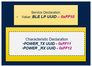
The following figure describes the application service structure:
Data throughput is exported as a Service
- POWER_TX UUID characteristic:
Transfer preconfigured data from client to server for power consumption measurement
- POWER_RX UUID characteristic:
Transfer preconfigured data from server to client for power consumption measurement
| Bluetooth® LE power service structure |
|---|
Combining the ability to run multiple application scenarios and measure power consumption, the STM32WBA power consumption tool offers an overview of software and hardware configurations and recommendations to test and achieve the best power consumption.
| STM32CubeMonitor-Power & STM32WBA power consumption measurement |
|---|
2. STM32WBA Bluetooth® Low Energy power application requirements
2.1. STM32WBA software and hardware board requirement
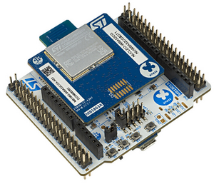
To measure the STM32WBA power consumption the NUCLEO-WBA5xx board is the best candidate to run this setup due to its PCB optimization, reduced components, and low cost.
- Depending on the targeted power consumption purpose one or two NUCLEO-WBA5xx hardware boards are required.
| NUCLEO-WBA5xx hardware Board. |
|---|
- Measuring the Bluetooth® Low Energy power peripheral in Advertising state, only one hardware board is required
- Measuring the Bluetooth® Low Energy power peripheral in Connected state, only one hardware board is required if connected to a smartphone via STBLEToolbox[3]. Or a second hardware board is optional to connect to Bluetooth® Low Energy power Central.
- Measuring the Bluetooth® Low Energy power Central in Connected state, two hardware boards are required. One for the Central and another one for the peripheral.
For more details on how to build an STM32WBA Bluetooth® Low Energy project you can refer to STM32WBA_Build_BLE_Project
2.2. Power measurement setup: software requirements
To measure the NUCLEO-WBA5xx power consumption the STM32CubeMonitor-Power [4] is used. For more details, you can refer to the STM32CubeMonitor-Power user manual [5]
2.3. Power measurement setup: hardware requirements
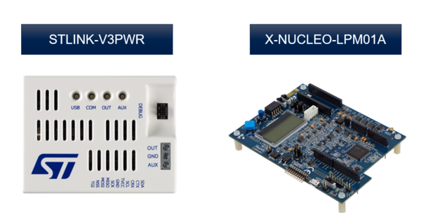
For the power measurement, STM32CubeMonitor-Power require to connect on one of the following hardware boards the X-NUCLEO-LPM01A [6] or the STLINK-V3PWR [7]. For the following topics, the focus is on the STLINK-V3PWR.
| Power consumption hardware boards |
|---|
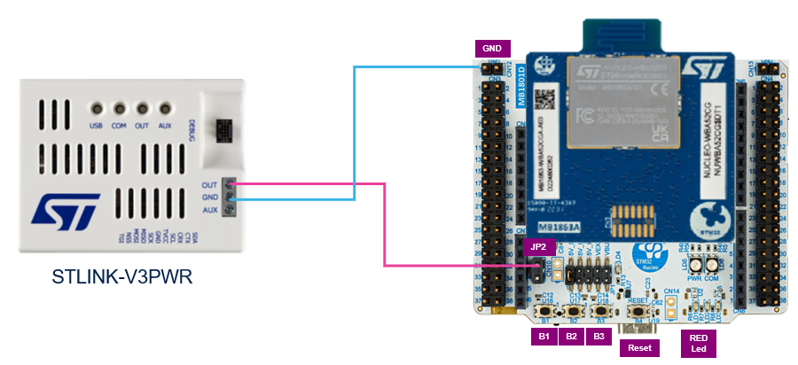
Power measurement setup overview:
| Power consumption setup |
|---|
- Connect the STLINK-V3PWR GND to the STM32WBA5xx GND.
- Remove the STM32WBA5xx jumper JP2
- Connect the STLINK-V3PWR OUT to the STM32WBA5xx JP2 pin 2:
| Power consumption : NUCLEO-WBA5xx connection |
|---|
3. Bluetooth® Low Energy power consumption application presentation
3.1. Bluetooth® Low Energy power consumption application setup overview
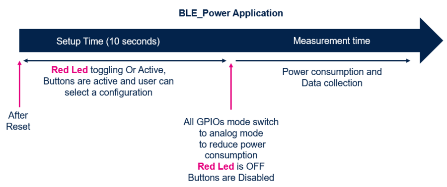
To avoid extra power consumption, the application has two phases:
- A setup phase: not in low power, all buttons are active for configuration
- A power measurement phase: enter in low power, all GPIOs are disabled
Application trace is by default disabled to avoid extra power consumption.
| Bluetooth® Low Energy power application overview |
|---|
Note:
- During setup time, STM32WBA5xx STLINK must be powered to use buttons.
- By default setup time is 10 seconds duration, but it can be modified in app_conf.h "Setup_Time " define variable.
3.2. Bluetooth® Low Energy peripheral power overview
The following chapter describes the application features and possible configurations. The application offers a default configuration. To align with the user application, listed defines in the following chapter can be modified depending on the needs.
3.2.1. Application general parameters
The following table defines the application general parameters.
| Bluetooth® Low Energy peripheral power general parameters(*) | ||||||||||||||||||||
|---|---|---|---|---|---|---|---|---|---|---|---|---|---|---|---|---|---|---|---|---|
|
- (*) Defines are available in app_conf.h
- (**) GPIOs configured in analog mode to avoid Schmitt trigger's extra power consumption. For more detail, you can refer to STM32 microcontroller GPIO hardware settings and low-power consumption application note [8]
3.2.2. Advertising power measurement
After reset, the Bluetooth® Low Energy power peripheral starts advertising. The following table summarizes the application possible configuration during an advertising/not connected state.
| Bluetooth® Low Energy peripheral advertising configuration(*) | ||||||||||||||||
|---|---|---|---|---|---|---|---|---|---|---|---|---|---|---|---|---|
|
- (*) Variables default values can be modified under app_conf.h.
- (**) 8 bytes combine 5 bytes for the name and 3 bytes for the flags.
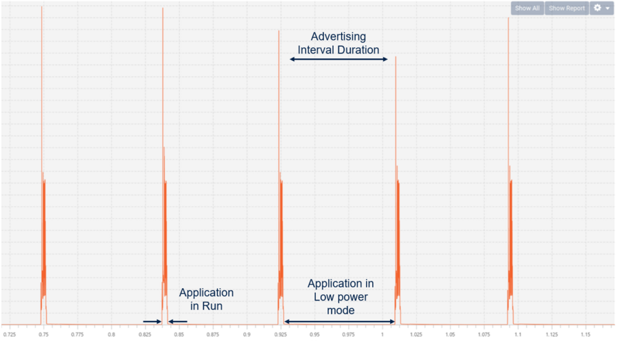
| Advertising power consumption |
|---|
Recommendations: Increasing the advertising interval reduces the power consumption for a better battery life.
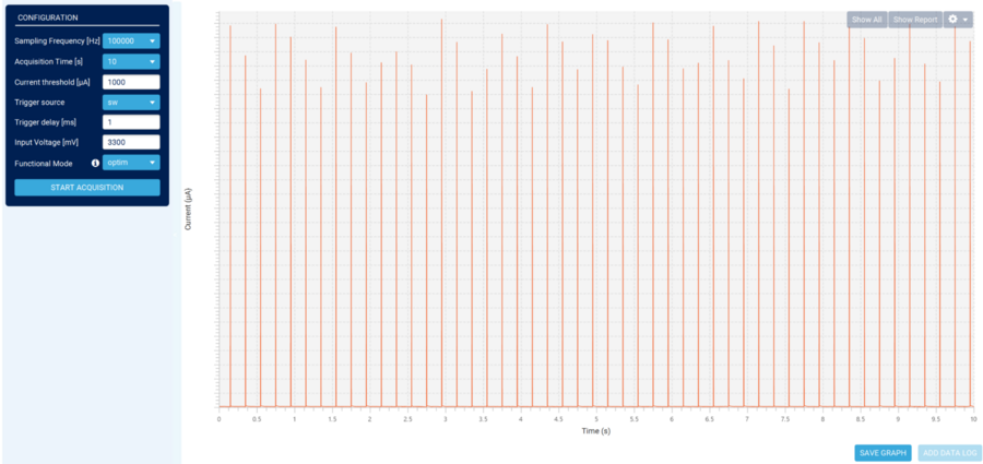
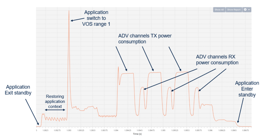
Zooming into the run mode activity shows the following graph:
| Connectable advertising power consumption in running phase (Exit from Standby) |
|---|
Notes:
- By default, the application is in VOS range 2 after exiting low power state. It is mandatory to switch to VOS range 1 before starting radio activity.
For more details, you can refer to the dedicated product reference manual [9]
- For more detail on Low power management, you can refer to STM32WBA Low power management
- Depending on the application requirement, some parameters can be modified for power consumption simulation.
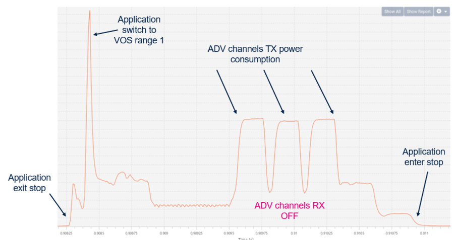
Here is an example of:
- Low power mode: Stop mode
- Advertising type : ADV_NONCONN_IND
| Non-connectable advertising power consumption in running phase (Exit from Stop) |
|---|
Notes:
- By default, the application is in VOS range 2 after exiting low power state, it is mandatory to switch to VOS range 1 before starting radio activity.
For more details, you can refer to the dedicated product reference manual.
- For more details on Low power management, you can refer to STM32WBA Low power management
- Depending on the application requirement, Stop mode has a higher power consumption during the application low power mode phase than Standby but a faster wake-up.
- Lower advertising packet size reduces the ADV Tx channels power consumption.
- During ADV_NONCONN_IND ADV Rx channels are OFF.
3.2.3. Connected mode power measurement
Connection to the peripheral can be made using the Bluetooth® Low Energy toolbox mobile app or the Bluetooth® Low Energy Power central via a second STM32 hardware board. In this chapter the focus will be on STBLEToolbox[10] mobile app connection.
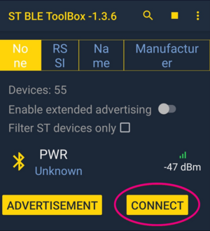
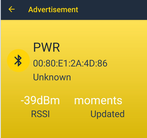
- Open your STBLEToolbox and start scanning for the application "PWR".
- Once scanned, press CONNECT to establish connection with the Bluetooth® Low Energy power peripheral.
| Bluetooth® Low Energy ToolBox connection to PWR peripheral |
|---|
Idle connection
When connection is established by default the PHY selected is 1M, empty LE packets are sent from the Central to maintain the connection. The delay between empty LE packets is defined by the connection interval.
| Default idle connection configuration | ||||||||||||||||
|---|---|---|---|---|---|---|---|---|---|---|---|---|---|---|---|---|
|
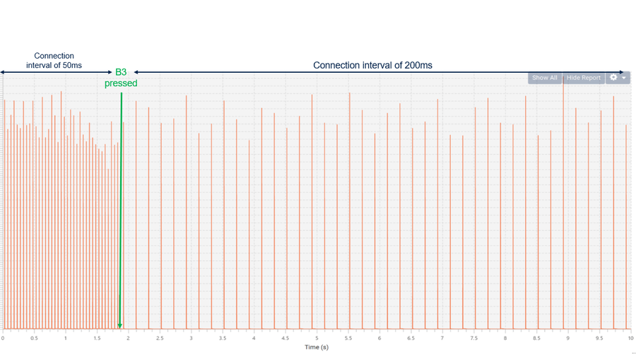
Just like the advertising interval, the connection interval has an impact on the application power consumption. The following figure shows the impact on power consumption by pressing B3 switching the connection interval from 50 ms to 200 ms.
| Switching connection interval |
|---|
Data transfer connection
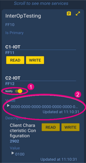
- To enable data transfer, notification must be enabled in the Bluetooth® Low Energy toolbox application.
- After enabling notifications, pressing button 1 toggles data transfer every second.
| Enabling data transfer |
|---|
3.3. Bluetooth® Low Energy central power overview
The following chapter focuses on the application features and possible configurations. The application offers a default configuration. To align with the user application, listed defines in the following chapter can be modified depending on the needs.
3.3.1. Application general parameters
The following table defines the application general parameters.
| Bluetooth® Low Energy peripheral power general parameters(*) | ||||||||||||||||||||
|---|---|---|---|---|---|---|---|---|---|---|---|---|---|---|---|---|---|---|---|---|
|
- (*) Defines are available in app_conf.h
- (**) GPIOs configured in analog mode to avoid the Schmitt trigger extra power consumption. For more details, refer to STM32 microcontroller GPIO hardware settings and low-power consumption application note [8]
Idle connection
By default, after the reset, the application initiates connection to the peripheral. It is important in the power central project to define the address of the peripheral device #define CFG_PERIPH_BD_ADDRESS
| Peripheral BD address |
|---|
After reset, the Bluetooth® Low Energy power central automatically connects to the Bluetooth® Low Energy power peripheral.
Once the connection is established, empty packets are exchanged each 50 ms.
The following table summarizes the possible configurations of the Bluetooth® Low Energy power central application:
| Bluetooth® Low Energy peripheral power general parameters(*) | ||||||||||||
|---|---|---|---|---|---|---|---|---|---|---|---|---|
|
(*) defines are available in app_conf.h
4. References
