Insights of the firmware and how to customize it.
1. Introduction
This user manual gives an insight into the motor control 6-step examples for the STMicroelectronics Motor Control System Development Kit (MCSDK).
The firmware examples implement a 6-step algorithm, also known as a trapezoidal algorithm. It allows to control a 3-phase permanent magnet (PMSM) or brushless direct current motor (BLDC).
This manual describes the way the user can open the ready-to-use examples as well as how to configure a set of parameters in order to customize the example as the target application.
In the following sections a short description of the main blocks of the algorithm is also provided.
1.1. List of acronyms and definition
| Acronym | Description |
|---|---|
| MCSDK | Motor control software development Kit |
| HW | Hardware |
| IDE | Integrated development environment |
| MCU | Micro-controller unit |
| GPIO | General purpose input output |
| ADC | Analog- to-digital converter |
| VM | Voltage mode |
| SL | Sensors-less |
| HS | Hall sensors |
| BEMF | Back electro motive force |
| FW | Firmware |
| LF | Low frequency |
| MF | Medium frequency |
| HF | High frequency |
| ZC | Zero-crossing |
2. Definitions
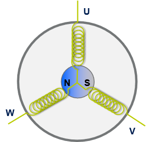
A brushless three-phase motor is composed as shown in Figure 1 by a fixed element, called stator, made of a set of three windings (such as phases) connected together at one side, and a moving element containing an internal permanent magnet called rotor. The rotor may have several pole pairs regularly distributed around the stator.
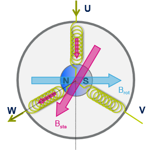
In six-step driving, the electrical cycle is divided into six commutation steps. At each step, the bus voltage is connected to one of the three phase windings of the motor while ground is connected to a second winding, forcing a current flowing through these two windings, and generating a stator magnetic field as shown in Figure 2. The third winding remains floating.
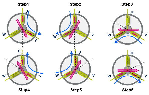
The orientation of the stator magnetic field is changed energizing the windings in the sequence shown in Figure 3.
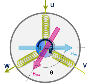
Since the rotor has a permanent magnetic field, the rotating stator magnetic field creates a torque that moves the rotor. The maximum torque is obtained when the electrical angle between the rotor and the stator is 90°. The orientation of the stator magnetic field is changed thanks to the six step commutation keeping the motor spinning, as explained in Figure 4.
3. 6-step firmware algorithms
3.1. Overview
The 6-step firmware reveals the position of the motor rotor every 60 electrical degrees (in sensor-less or sensored mode). Based on this information, it computes the time for the next step commutation, and calculates the duty cycles for the PWM signals that drive the output power transistors. These transistors control the motor phase voltages allowing to reach a target speed.
The 6-step firmware can be viewed as a set of components, each with a different task.
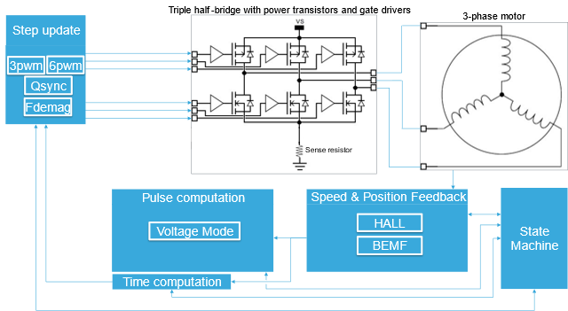
The following list describes the components shown in Figure 5:
- Speed and position feedback component: BEMF sensing is used with the sensors-less driving mode while Hall sensors are exploited with the sensored driving mode.
- Pulse computation component (voltage mode - VM) is used. A proportional-integral (PI) controller algorithm is employed for the speed loop control.
- Time computation component: it manages the step change, and applies the configuration of the timers set by the step update component.
- Step update component: it updates the configuration of the timers, hence the proper energization of the phases, according to the selected driving mode (3pwm, 6pwm, synchronous rectification, quasi-synchronous rectification, fast demagnetization). See sections 4.2.7 and 4.2.8 for more details.
- State machine component: each component operates according to the state machine status and influences it.
3.2. Voltage driving mode
The motor speed is controlled by varying the duty cycle of the pulse width modulated voltages applied to the motor phases.
3.3. Sensor-less algorithm
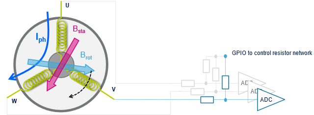
In the sensor-less mode, the position of the rotor is obtained by detecting the zero-crossing of the Back ElectroMotive Force sensed at the floating phase. This is commonly done using an ADC as shown in Figure 6. In particular, when the magnetic field of the rotor crosses the high impedance phase, the corresponding BEMF voltage changes its sign (zero-crossing). The BEMF voltage can be scaled at the ADC input, thanks to a resistor network controlled by a GPIO. When the GPIO output is low, the resistor network divides the voltage coming from the motor phase.
The BEMF zero-crossing detection is assessed through two different thresholds: one taken when the BEMF is expected to rise, and the other one when expected to fall. These two thresholds assume different values depending on the PWM state during BEMF voltage acquisition. In particular, the threshold nominal value is 0 V if BEMF is acquired during the PWM OFF-time, and VBUS/2 if BEMF is acquired during the PWM ON-time (voltage range adjustment is carried out during an ON-time acquisition thanks to the activation of the resistor network divider).
When a BEMF voltage zero-crossing is detected (= the acquired value crosses the threshold), the FW reprograms an MCU timer, designated as the LF timer, with a period equal to half of a step time. Once elapsed, an interrupt is triggered. Then, the next step is applied. The time between the zero-crossing detection, and the step commutation can be tuned by changing the ZCD_TO_COMM parameter (see section 4.2.2).
After a step commutation, a new motor phase becomes floating. Before starting to acquire the BEMF voltage on that phase, it must be demagnetized thus avoiding the noise coming from the demagnetization current to affect the measurement. The demagnetization time can be customized by the user in tenths of percentage of the step time by changing the RUN_DEMAG_TIME_STEP_RATIO parameter (see section 4.2.3)
Since BEMF voltage is proportional to the speed, during startup, the firmware cannot rely on zero-crossing detection to determine the rotor position. Hence, the motor is accelerated in open loop control and BEMF acquisition is activated once a pre-configured target speed is reached. The start-up procedure includes the following phases:
Alignment: the motor coils are energized to have the rotor aligned to a known position
Acceleration: the steps are changed following a constant acceleration imposed by the FW
Validation: once a pre-defined start-up speed target is reached, BEMF acquisition starts and speed loop is closed once zero crossing is detected
One or more error flags are raised when one of the the following event occurs:
- BEMF Zero crossing is not detected during validation phase (Software error, Speed Feedback error)
- Validation phase is not successfully carried out (Start Up Failure error)
- Computed speed exceeds LF timer period (6Step Duration error)
- Over-current signal (Over Current error)
3.3.1. SL tasks
For a better understanding of the firmware, a short description of the tasks performed by the firmware in the sensor-less driving mode is provided:
- High frequency task (HF task): It originates from the triggering of the ADC. When the ADC conversion is complete, the ADC measurement is processed. This task manages the transition from the start-up procedure (open loop) to the RUN state (close loop), it computes the duration for the next step and the demagnetization time.
- Medium frequency task (MF task): It is executed when a system tick interrupt is received. It manages the acceleration phase during start-up procedure, the duty cycle update (hence the pulse) of the HF PWMs, the update of the ADC triggering settings and the communication with the Motor Pilot GUI.
- Low frequency task (LF task): The frequency of this task depends on the current speed of the motor. It is executed after a LF timer interrupt is received. It controls the 6step sequence change and it computes the speed of the motor.
3.4. Hall sensors algorithm
In this driving mode, the positioning of the rotor is obtained by reading the digital signals coming from the Hall sensors (connected to three GPIOs). Based on the detected Hall status, the firmware uses two truth tables (for clockwise and counterclockwise directions) to infer the step number and to decide which phases to energize, as shown in Figure 7.
*
During the alignment time, the position of the rotor is acquired and the motor windings are energized according to Figure 7. As soon as the rotor moves and the Hall status changes, the motor is assumed running.
When a sensors commutation is detected, the new status is acquired. At the same time, the step is changed and the PWMs updated accordingly.
One or more error flags are raised when one the following event occurs:
- The acquired Hall sensors status is not allowed (Software error, Speed Feedback error)
- The alignment time elapses and no sensors commutation is detected (Start Up Failure error)
- Unexpected/wrong communications for three times in a row (Software error)
- No communication is detected within a configurable period (6Step Duration error)
- Over-current signal (Over Current error)
3.4.1. HS tasks
For a better understanding of the firmware, a short description of the tasks performed by the firmware in sensor driving mode is provided:
- High frequency task (HF task): it is used for optional ADC measurement (bus voltage sensing, load current reading, temperature sensing)
- Medium frequency task (MF task): It is executed when a system tick interrupt is received. This task controls the alignment time, it manages the duty cycle update (hence the pulse) of the HF PWMs, the update of the ADC triggering settings for temperature and the bus voltage acquisition (if enabled) and the communication with the Motor Pilot GUI.
- Low frequency task (LF task): the frequency of this task depends on the speed of the motor. It is executed after any Hall sensor commutation. It controls the 6step sequence change and it computes the speed of the motor.
4. 6-step firmware examples presentation
The following table shows supported examples with a list of driving mode capabilities and pre-configured motor:*
| Control board | Power board | Driving mode | Default motor |
|---|---|---|---|
| STEVAL-SPIN3201 | STEVAL-SPIN3201 | Hall sensors
Voltage mode |
Shinano
LA052-080E3NL1 |
| STEVAL-SPIN3202 | STEVAL-SPIN3202 | Sensorless
Voltage mode |
Shinano
LA052-080E3NL1 |
| STEVAL-SPIN3202 | STEVAL-SPIN3202 | Hall sensors
Voltage mode |
Shinano
LA052-080E3NL1 |
| STEVAL-SPIN3204 | STEVAL-SPIN3204 | Sensorless
Voltage mode |
Shinano
LA052-080E3NL1 |
| STEVAL-SPIN3204 | STEVAL-SPIN3204 | Hall sensors
Voltage mode |
Shinano
LA052-080E3NL1 |
| Nucleo-F302R8 | X-NUCLEO-IHM07M1 | Sensorless
Voltage mode |
Bull Running
BR2804-1700kv |
| Nucleo-F302R8 | X-NUCLEO-IHM07M1 | Hall sensors
Voltage mode |
Shinano
LA052-080E3NL1 |
| Nucleo-G431RB | X-NUCLEO-IHM16M1 | Sensorless
Voltage mode |
GimBal
GBM2804H-100T |
| Nucleo- G431RB | X-NUCLEO-IHM16M1 | Hall sensors
Voltage mode |
Shinano
LA052-080E3NL1 |
| EVSPIN32F0251S1 | EVSPIN32F0251S1 | Sensorless
Voltage mode |
Shinano
LA052-080E3NL1 |
| EVSPIN32F0251S1 | EVSPIN32F0251S1 | Hall sensors
Voltage mode |
Shinano
LA052-080E3NL1 |
| STEVAL-PTOOL1V1 | Hall sensors
Voltage mode |
Shinano
LA052-080E3NL1 |
The projects can be opened from the main window of the MCSDK, in the section @Example Projects@.
After choosing one of the available 6-step examples, the user must save it to an empty folder location but MUST NOT rename it, otherwise the example does not properly work.
A folder with the same name of the project containing the #example_name.ioc file is created.
Clicking on the "down arrow" icon on the task menu, the user is asked to select one of the available IDEs (EWARM, or MDK-ARM or ST STM32CubeIDE). By clicking on the UPDATE button, the source code generation starts. Note that the GENERATE button usage might overwrite the existing default values resulting in a generation process failure.
The output is saved in the working folder: The code is ready-to-use with the default motor listed in Table 2. The project can now be opened and built with the selected IDE and the resulting binary image loaded into the MCU board.
The default algorithm values, as well as the motor parameters, can be customized through STM32CubeMX.
In particular, the user might open the #example_name.ioc file with STM32CubeMX in the working folder, then select the “Middleware” category on the left-side menu and “MotorControl” option.
In the “Configuration” window, “Parameter Settings” tab, the available parameters are listed. Once the user has completed the modifications, the source code is updated by clicking on the “GENERATE CODE” button. If the parameter of interest cannot be found in this section of STM32CubeMX, see the instructions to follow in section 4.3.
4.1. Motor Pilot GUI
To improve the user experience with the examples, a dedicated GUI for 6-step firmware has been developed.
The user can select it and load it from the “GUI” menu of the Motor Pilot application, clicking on “Load GUI” and browsing in the MCSDK installation folder \Utilities\PC_Software\STMotorPilot\GUI\defaultApp_6STEP.qml.
The connection with the board can be established by selecting an available COM port with baud rate 115200.
Commands to start/stop and change the motor speed can be sent in the “Control” and “Speed Control” box: a command with a positive speed value sets the motor spinning clockwise, while a negative speed value sets the direction counterclockwise. Changing speed sign (such as direction) does necessarily send a stop command.
Additionally, proportional and integral gains of the speed loop can be changed by clicking “Advanced Configuration”.
4.2. 6-step parameters
In the following sections a detailed description of the 6step parameters that can be set in STM32CubeMX is provided. When changing the motor, these parameters may be adapted accordingly.
4.2.1. Low frequency timer management
The LF timer is used to compute the speed of the motor and to update the timer settings according to the current step of the 6step sequence, both in sensor-less and Hall sensors driving mode. The user must take into consideration the speed range the application is going to target when changing the default values.
- LF_TIMER_PSC: low frequency prescaler value (0 ÷ 65535)
- LF_TIMER_ARR: low frequency timer auto-reload value (0 ÷ 65535)
4.2.2. BEMF zero crossing management
As described in section 3.3, to detect the zero crossing, the algorithm compares the BEMF voltage with two different thresholds. Depending on the fact that BEMF voltage is expected to increase or decrease during the current step, this threshold assumes different values when the ADC triggering is performed during the ON or the OFF-time of the PWM driving signal. The following parameters are used only in the projects with sensor-less driving mode to determine the position of the rotor.
- BEMF_PWM_ON_DISABLE_THRES: threshold [% of the HF timer period] set to disable the acquisition of the BEMF during the ON-time. If the current duty cycle of the PWM driving signal is lower than BEMF_PWM_ON_DISABLE_THRES, the following thresholds and ADC triggering point are considered.
- BEMF_ZC_THRESHOLD_UP_V: threshold [V] taken into account when BEMF is expected to increase and the acquisition is performed during the OFF-time
- BEMF_ZC_THRESHOLD_DOWN_V: threshold [V] taken into account when BEMF is expected to decrease and the acquisition is performed during the OFF-time
- BEMF_ADC_TRIG_TIME: ADC triggering point set if BEMF voltage is acquired during the OFF-time [% of the HF timer period]
- BEMF_PWM_ON_ENABLE_THRES: threshold [% of the HF timer period] set to enable the acquisition of the BEMF during the ON-time. If the current duty cycle of the PWM driving signal is higher than BEMF_PWM_ON_ENABLE_THRES, the following thresholds and ADC triggering point are considered.
- BEMF_ZC_THRESHOLD_UP_ON_V: value [V] taken into account to determine the threshold when BEMF is expected to increase and the acquisition is performed during the ON-time.
Threshold_UP_ON_V =BEMF_ZC_THRESHOLD_UP_ON_V + (NOMINAL_BUS_VOLTAGE_V)/(2 ×BEMF_ON_SENSING_DIVIDER ) - BEMF_ZC_THRESHOLD_DOWN_ON_V: value [V] taken into account to determine the threshold when BEMF is expected to decrease and the acquisition is performed during the ON-time
- BEMF_ZC_THRESHOLD_UP_ON_V: value [V] taken into account to determine the threshold when BEMF is expected to increase and the acquisition is performed during the ON-time.
Threshold_DOWN_ON_V =BEMF_ZC_THRESHOLD_DOWN_ON_V + (NOMINAL_BUS_VOLTAGE_V)/(2 × BEMF_ON_SENSING_DIVIDER )
- BEMF_ADC_TRIG_TIME_PWM_ON: ADC triggering point set if BEMF voltage is acquired during the ON-time [% of the HF timer period]
- BEMF_ON_SENSING_DIVIDER: dividing factor used to re-scale the BEMF voltage acquired during the ON time. It depends on the resistor network soldered on the power board
- ZCD_TO_COMM: delay (in electrical degrees) between the zero-crossing detection and the step commutation. Nominally 30 degrees
4.2.3. Demagnetization time management
The following parameters are used to configure the demagnetization time (refer to section 3.3) in the projects with sensor-less driving mode.
- RUN_DEMAG_TIME_STEP_RATIO: Tenths of percentage of step time allowed for demagnetization [.1%]
- RUN_SPEED_THRESHOLD_DEMAG: Speed threshold above which the RUN_DEMAGN_DELAY_MIN is applied [rpm/min];
- DEMAGN_DELAY_MIN: Demagnetization delay in number of HF timer periods elapsed before the first BEMF ADC measurement is processed to detect the BEMF zero crossing;
- VALIDATION_DEMAGN_DELAY: Demagnetization delay in number of HF timer periods elapsed before the first BEMF ADC measurement is processed to detect the BEMF zero crossing during the validation phase;
4.2.4. Hall sensors commutation management
The following parameters are used only in the projects with Hall sensors positioning feedback.
- ALIGNMENT_FORCE_STEP_CHANGE: During the alignment phase, the Hall status is acquired and the PWMs are activated accordingly. If an unexpected or a wrong commutation is detected, the firmware may force a step change trying to recover the synchronism. This parameter enables/disables this feature.
- RUN_STAY_WHILE_STALL_MS: it sets the timeout of the firmware in milliseconds when a motor stall is detected (no Hall sensors commutation).
- RUN_COMMUTATION_DELAY: It is the delay between the Hall status change and the 6step sequence change. It represents the number of low frequency timer counts between the two events; so, the real duration of this delay depends on the setting of the prescaler of the low frequency timer (see section 4.2.1).
- DEFAULT_TARGET_SPEED_RPM: it is the target speed reached by the motor [rpm/min]
4.2.5. Sensor-less start-up management
The following parameters allow the configuration of the start-up procedure (alignment, acceleration and validation phases).
- ALIGNMENT_STEP: During the alignment phase, the rotor is put in a known position before running the motor. To do this, the power switches must be set to a specific configuration corresponding to a predetermined position of the stator vector. This configuration is not an ordinary position but it is the intermediate position between two steps, depending on the ALIGNMENT_STEP parameters and the motor direction. For instance, ALIGNMENT_STEP=1 and DIRECTION=clockwise between step 6 and step 1, ALIGNMENT_STEP=1 and DIRECTION=counterclockwise between step 1 and step 2
- ALIGNMENT_TIME: It is the time in ms between the energization of the outputs for the alignment and the beginning of the acceleration phase
- STARTUP_DUTY_CYCLE: It is the duty cycle applied during the alignment phase [% of the high frequency period]
- STARTUP_SPEED_TARGET: It is the target speed reached by the motor at the end of the acceleration phase [rpm/min]
- K_TORQUE: It is the extra torque applied to the motor in order to accelerate in open loop. Usually ranging from 1.2 and 1.5, it allows the motor to increase the speed in open loop (without knowing rotor position).
4.2.6. Speed loop PID management
The proportional and integral gains of the speed loop controller can be changed run-time with the Motor Pilot interface through the “Speed Kp” and “Speed Ki” controls in the “Advanced Configuration” tab.
- PID_OUTPUT_MIN and PID_OUTPUT_MAX are used to limit the output of the PID controller thus setting a minimum and a maximum instant variation applied to the speed by the controller. This avoids out-of-range corrections but may affect the responsiveness of the loop.
- PID_OUTPUT_MIN and PID_OUTPUT_MAX are defined as tenths of percentage of the high-frequency timer period.
4.2.7. Fast-demagnetization option
When the microcontroller switches from one step to the next, the non-excited winding needs a certain demagnetization time. During this time, the current in the winding continues in the same direction but decreases to zero. To accelerate the demagnetization, the PWM signal must be applied to the low-side switch during the step when the demagnetizing current is flowing from the bridge to the motor phases. Refer to Table 3 for a description of the firmware implementation
The FAST_DEMAG enables the fast demagnetization option, changing the driving signals during the demagnetization phase according to the below table. Refer to UM0708 for further details.
| Step | MOSfet On (HigSide + LowSide) |
Demagnetization current |
PWM applied with FAST_DEMA=1 |
|---|---|---|---|
| Step1 | PhaseU+PhaseV | PhaseW
(from bridge to motor) |
PhaseV (LS) |
| Step2 | PhaseU+PhaseW | PhaseV
(from motor to bridge) |
PhaseU (HS) |
| Step3 | PhaseV+PhaseW | PhaseU
(from bridge to motor) |
PhaseW (LS) |
| Step4 | PhaseV+PhaseU | PhaseW
(from motor to bridge) |
PhaseV (HS) |
| Step5 | PhaseW+PhaseU | PhaseV
(from bridge to motor) |
PhaseU (LS) |
| Step6 | PhaseW+PhaseV | PhaseU
(from motor to bridge) |
PhaseW (HS) |
FAST_DEMAG option is available with STEVAL-SPIN3202 and STEVAL-SPIN3204 control boards in sensor-less mode only.
4.2.8. Quasi-synchronous option
By default, the power stage is driven by the algorithm in fast decay mode.
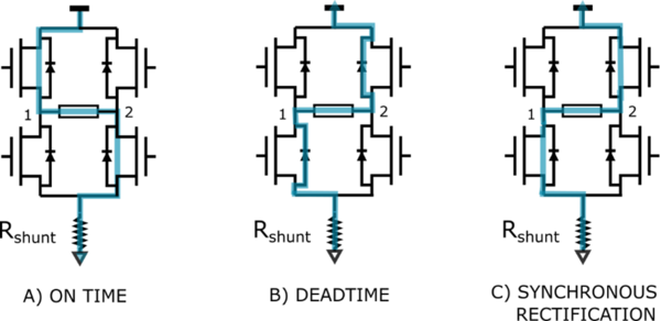
At the start of the OFF-time, both the power MOS of the energized phases are switched off and the current recirculates through the two opposite freewheeling diodes. The current decays with a high di/dt since the voltage across the coil is the power-supply voltage. After the deadtime, the low-side MOS and the high-side MOS in parallel with the conducting diode are turned on in synchronous rectification mode (see Figure 9).
In applications where the motor current is low, the load current may decay completely to zero and rise in the opposite direction.
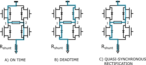
To avoid this, the QUASI_SYNC option may be enabled: The lower power MOS is not turned on in synchronous rectification mode preventing the current to reverse. This operation is called “Quasi-synchronous rectification mode” (see Figure 10).
QUASI_SYNC option is available with STEVAL-SPIN3202 and STEVAL-SPIN3204 control boards in sensor-less mode only.
QUASI_SYNCH and FAST_DEMAG options are incompatible one another. When both are enabled, only FAST_DEMAG is considered.
4.2.9. Motor configuration management
The following parameters may be changed if a different motor is selected for the target application.
- POLE_PAIR_NUM: number of pole pairs
- RS: single phase resistance [Ohm]
- LS: single phase inductance [mH]
- MOTOR_VOLTAGE_CONSTANT: Back electromotive force constant [Vrms/krpm]
- NOMINAL_BUS_VOLTAGE_V: Bus voltage [V]
5. Parameter visibility in STM32CubeMX using MCSDK 5.Y.1 (and later)
If, after opening the example project with STM32CubeMX, a configuration parameter cannot be found in the Middleware->MotorControl->ParameterSettings window the following procedure must be followed:
- Close STM32CubeMX.
- Open the example IOC file with a text editor.
- Identify the proper configuration setting in the list (for instance, if the number of motor pole pairs need to be changed, the user must look for the line MotorControl.POLE_PAIR_NUM) and change the setting value as intended.
- Save and close the file.
- Reopen the IOC file with STM32CubeMX to carry out the code generation process.
