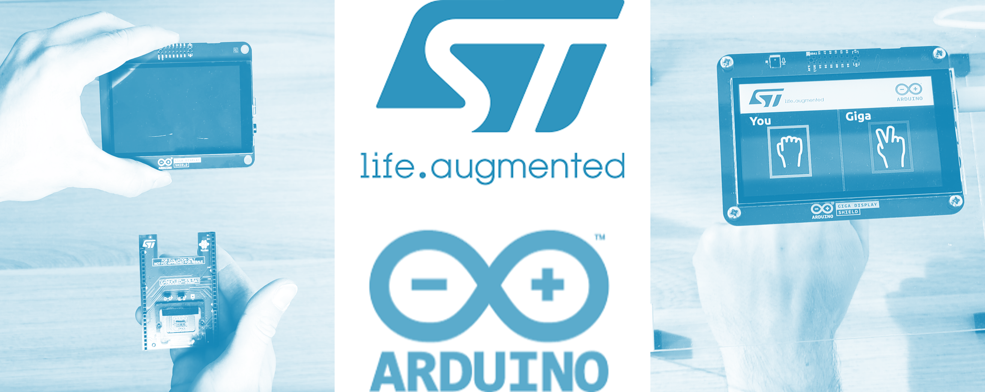
In this tutorial, artificial intelligence (AI) and a Time-of-Flight (ToF) sensor are used to create a rock-paper-scissors game.
The goal is to demonstrate how to use NanoEdge™ AI Studio and Arduino IDE for the creation of any potential project using AI.
NanoEdge AI Studio (the Studio) is a tool developed by STMicroelectronics especially designed for embedded profiles to help them acquire an AI library to embed in their project, only using their data.
Through a simple and step-by-step process, this tutorial shows how to:
- Collect data related to your use case
- Use the tool to get the best model with little effort
NanoEdge AI Studio libraries are compatible with any Cortex®-M core. Since its version 4.4, the tool is able to compile libraries ready to import directly in Arduino IDE.
A video version of this tutorial is available here: https://youtu.be/fTOLMCeYUEw
1. Goals
- Create a rock-paper-scissors game using ToF data and AI from scratch.
- Learn, through this example, how to use NanoEdge AI Studio to integrate AI easily into any future projects.
2. Hardware and software needed
Hardware:
- An Arduino GIGA R1 WiFi board
- An Arduino GiGA Display Shield
- An STMicroelectronics Time-of-Flight expansion board: X-NUCLEO-53L5A1
- A USB Type-A or USB Type-C® to Micro-B cable to connect the Arduino board to the desktop running NanoEdge AI Studio
Software:
- To program the board, use the Arduino Web Editor or install the Arduino IDE. Setup details are provided in the next sections.
- To create and get the AI model for the sign recognition of the rock, paper, and pair of scissors, use NanoEdge AI Studio v4.4 or above.
Note: Windows® users are advised to use Arduino IDE 1.8.19 and not the version available in the Windows Store®.
2.1. Hardware setup
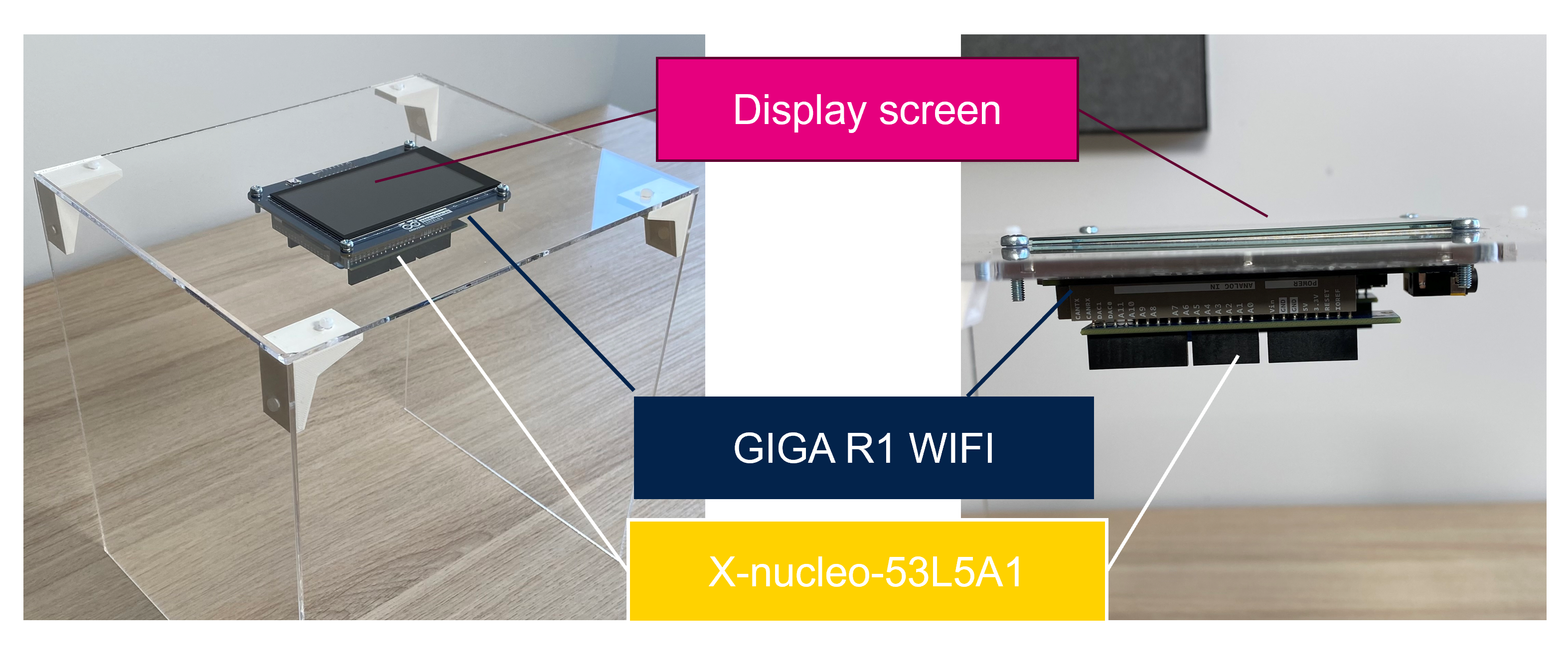
About the setup arrangement, make sure as in the picture below to plug:
- The display screen on top of the Arduino GIGA R1 WiFi board
- The ToF expansion board under the Arduino board
Important:
Modify the I2C communication pins between the ToF and the Arduino board to avoid a conflict with the display screen:
- Plug a jumper wire from the SDA1 pin to the 20SDA pin.
- Plug another wire from the SCL1 pin to the 21SCL pin.
3. NanoEdge AI Studio
For any part linked to NanoEdge AI Studio, an online documentation is available at https://wiki.st.com/stm32mcu/wiki/AI:NanoEdge_AI_Studio
3.1. Install
The first step is to install NanoEdge AI Studio:
- Navigate to the download link at https://stm32ai.st.com/download-nanoedgeai/
- Fill out the form
- Receive an email with the license needed to use the Studio
- Wait for the download to complete
- Launch the .exe to start the installation
- Once the installation is complete, enter the license; You are then ready to use the Studio!
In case of trouble during the installation, refer to the useful links below:
- https://wiki.st.com/stm32mcu/wiki/AI:NanoEdge_AI_Studio#Running_NanoEdge_AI_Studio_for_the_first_time
- https://community.st.com/t5/stm32-mcus/nanoedge-ai-studio-install-activation-troubleshooting/ta-p/624832
3.2. Create a project
In Nanoedge AI Studio, four kinds of projects are available, each serving a different purpose:
- Anomaly detection (AD): to detect a nominal behavior and an abnormal one. Can be retrained directly on board.
- 1-class classification (1C): Create a model to detect both nominal and abnormal behavior but with only nominal data. (In case you cannot collect abnormal examples)
- n-class classification (nC): Create a model to classify data into multiple classes that you define
- Extrapolation (Ex): Regression in short. To predict a value instead of a class from the input data (a speed or temperature for example).
Since the purpose of this tutorial is to create an AI able to recognize three signs (rock, paper, and scissors), click on N class classification >Create new project
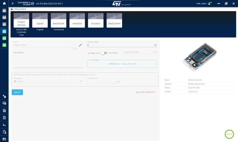
In the project settings:
- Enter the Name of your project
- Define a RAM and a Flash memory limit if needed
- Click Your target, then go to the ARDUINO BOARDS tab and select the GIGA R1 WiFi
- In sensor type, enter Generic and 1 as the number of axes
Then click on NEXT.
Note: The 8x8 ToF matrix of 64 values is used. Since each of the 64 distance measurements is taken independently from the others, it is possible to use only one axis to represent the data.
3.3. Data collection
In the Signals part of NanoEdge AI Studio, four datasets must be imported:
- Nothing: When we are not playing
- Rock
- Paper
- Scissors
The ToF collects data in an 8x8 matrix, so that every signal in the dataset is of size 64.
The next step is to collect data to create four datasets containing each various examples of the same sign.
Arduino code for data collection: To collect data, create a new project in Arduino IDE and copy the following code:
#include <Wire.h>
#include <SparkFun_VL53L5CX_Library.h> //http://librarymanager/All#SparkFun_VL53L5CX
SparkFun_VL53L5CX myImager;
VL53L5CX_ResultsData measurementData; // Result data class structure, 1356 bytes of RAM
int imageResolution = 0; //Used to pretty print output
float neai_buffer[64];
void setup() {
  Serial.begin(115200);
  delay(100);
  Wire.begin(); //This resets to 100kHz I2C
  Wire.setClock(400000); //Sensor has max I2C freq of 400kHz
  if (myImager.begin() == false)
  {
    Serial.println(F("Sensor not found - check your wiring. Freezing"));
    while (1);
  }
  myImager.setResolution(8*8); //Enable all 64 pads
  myImager.setRangingFrequency(15); //Ranging frequency = 15Hz
  imageResolution = myImager.getResolution(); //Query sensor for current resolution - either 4x4 or 8x8
  myImager.startRanging();
}
void loop() {
  if (myImager.isDataReady() == true)
  {

    if (myImager.getRangingData(&measurementData)) //Read distance data into array
    {
      for(int i = 0 ; i < imageResolution ; i++) {
        neai_buffer[i] = (float)measurementData.distance_mm[i];
      }
      for(int i = 0 ; i < imageResolution ; i++) {
        Serial.print(measurementData.distance_mm[i]);
        Serial.print(" ");
      }
      Serial.println();
    }
  }
}
Two libraries must be added to the project:
- Wire.h for I2C communication: click on Sketch > Include Library > Wire
- SparkFun_VL53L5CX_Library: to use the ToF: Sketch > Include Library > Manage Library > SparkFun_VL53L5CX_Library and click on install
Once ready, click on the verify sign to compile the code, and then to the right arrow to program the code onto the board. Make sure that the board is connected to the PC beforehand.
Make sure that the right COM port is selected. Click on Tools > Port to select it. If the board is plugged in, its name is displayed among the ports.
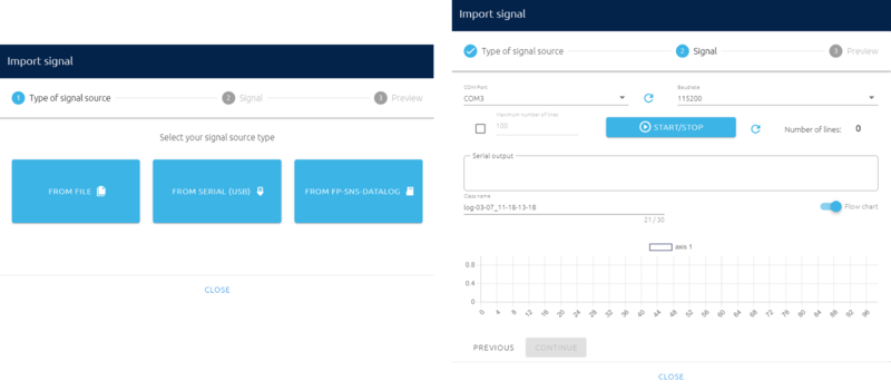
Back in NanoEdge: In the step SIGNALS:
- Click on ADD SIGNAL
- Click on FROM SERIAL
- Make sure to select the right COM port.
- Leave the Baudrate as it is
- Click on the maximum number of lines and enter 500
- Click on START/STOP to log data
- Once finished, click on CONTINUE and then onIMPORT
VERY IMPORTANT:
Do not log data as if playing the rock-paper-scissors game multiple times, log a sign continuously at different positions below the captor (up, down, left, right, etc). For example, do the scissor sign and move below the captor while collecting the 500 signals without ever leaving the captor's sight.
We really need to only have data corresponding to the class only. If you simulate playing to log data, you will have data corresponding to no signs (because you are not in the captor's sight) and then data corresponding to the class.
Make sure not to be too close to the ToF, as it will not be able to see anything but a big object covering the whole matrix.
3.4. Finding the best model
Go to the BENCHMARK step.
In this step, NanoEdge AI Studio will look for the best preprocessing of your data, model, and parameters for this model in order to find the best combination for your use case.
Once done, you will be able at the end of the project to compile the combination found as an AI Library to import in Arduino IDE.
- Click NEW BECHMARK
- Select the four classes collected previously.
- Click START
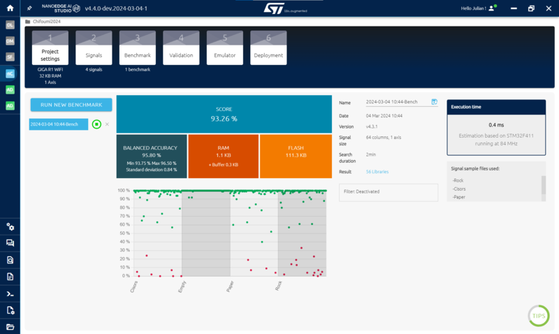
The studio displays a few metrics:
- Balanced accuracy which is the weighted mean of good classification per class
- RAM and FLASH need
- Score: This metric takes into account the performance and size of the model found.
The time required for the benchmark is heavily correlated with the size of the buffer used and its quantity. The benchmark will improve fast at the beginning and tend to slow down to find the most optimized library at the end. So you can stop the benchmark when you are satisfied with the results (above 95% is a good reference).
3.5. Validate the model found
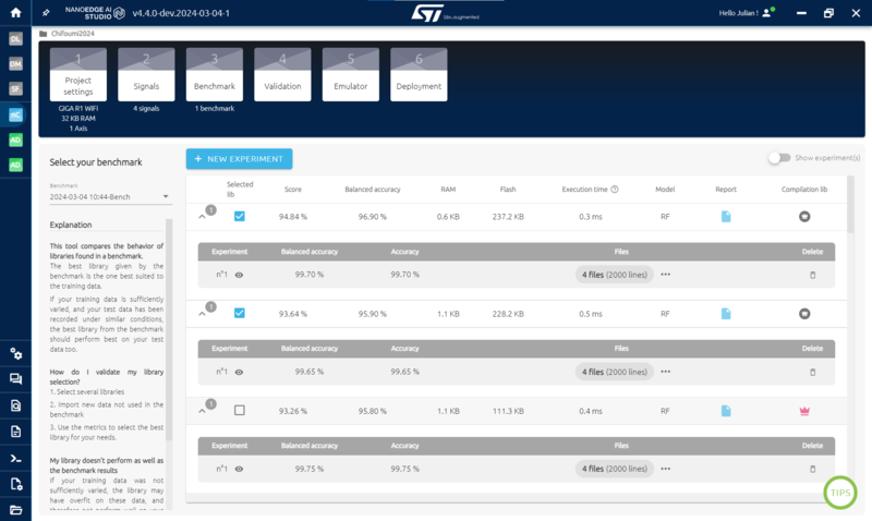
- The validation and emulator steps are made to make sure that the library found is indeed the best. *To achieve that, it is recommended to test the few best libraries with new data and make sure that the one selected is the best.
Note: To collect new datasets for validation, you can go back to the step signal, import new datasets via serial, and download them to use them in validation:
- Go to the Validation Step
- Select 1 to 10 libraries.
- Click NEW EXPERIMENT
- Import a new dataset for the 4 classes.
- click START
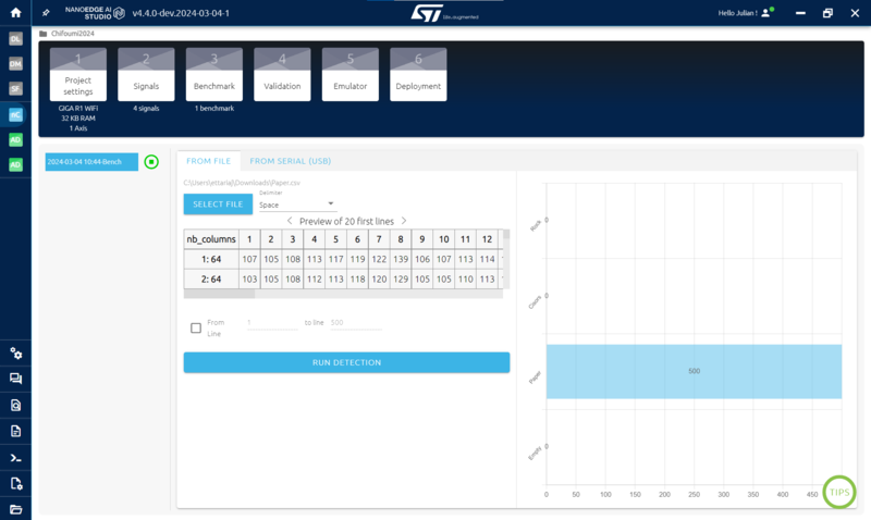
You also have the emulator to push tests further if needed on one library and to test it live using serial for a quick demo, for example:
3.6. Getting the Arduino library
To obtain the AI library containing the model and the function to add it to your Arduino code:
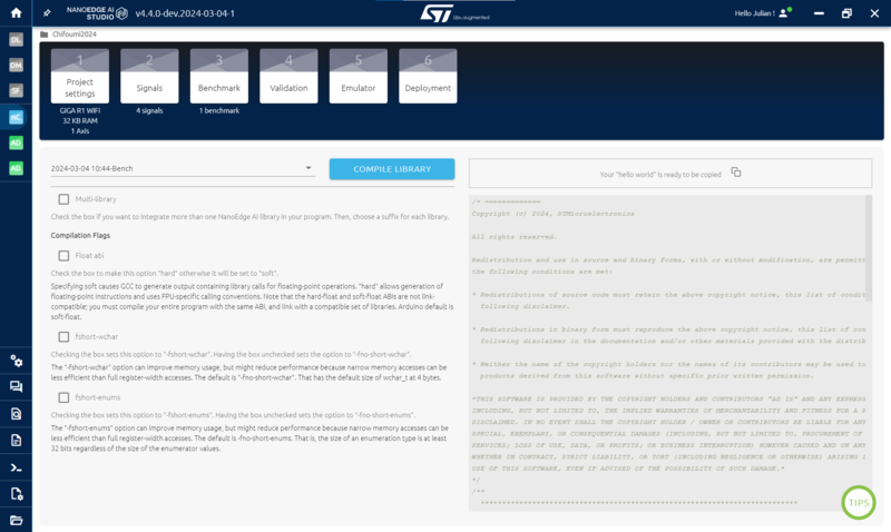
- Go to Compilation
- Important: leave the Float abi unchecked for the GIGA R1 WIFI.
- Click COMPILE LIBRARY
The output is a .zip file that we will directly import into the Arduino IDE later.
4. Arduino IDE
4.1. Library setup
After getting the zip containing the AI library from NanoEdge AI Studio, create a new project by clicking File > New.
To make this project work, we need a few libraries.
- Click on Sketch > Include Library > Wire to include the Wire.h library for I2C communication (it is installed by default)
To add a standard library, click on Sketch > Include Library > Manage Library and install the following libraries:
- ArduinoGraphics: for display on the screen.
- SparkFun_VL53L5CX_Library: to use the ToF.
To add the NanoEdge AI Studio library:
- Extract the .zip provided by NanoEdge AI Studio after compilation.
- In Arduino IDE click on Sketch > Include Library > Add .ZIP Library…
- Find the previously extrated content and import the .zip file in the Arduino folder.
We also need to add incbin.h:
- You can find incbin.h here: https://github.com/graphitemaster/incbin/blob/main/incbin.h
- Copy and paste it inside the folder containing the .ino file of the project.
Lastly, we need to select the GIGA R1 WIFI as our board:
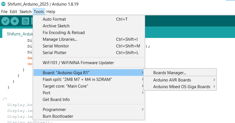
- Click Tools > Board: “your actual board” > Boards Manager…
- Search and install Arduino Mbed OS Giga Boards.
- Then go back to Tools > Board: “your actual board” > Arduino Mbed OS Giga Boards >Arduino Giga R1
Note: Arduino_H7_Video.h is automatically added when selecting the board, you don't need to add it manually.
4.2. Code
The following code takes care of three main parts:
- Collect data from the ToF.
- Use the NanoEdge AI Library every time we collect data from the ToF to detect what sign is being played.
- Load and display images corresponding to the sign detected by NanoEdge AI Studio.
Here is the code:
#include "Arduino_H7_Video.h"
#include "ArduinoGraphics.h"
#include "incbin.h"
#include <Wire.h>
#include <SparkFun_VL53L5CX_Library.h> //http://librarymanager/All#SparkFun_VL53L5CX
#include "NanoEdgeAI.h"
#include "knowledge.h"
// Online image converter: https://lvgl.io/tools/imageconverter (Output format: Binary RGB565)
//#define DATALOG
#define SCREEN_WIDTH  800
#define SCREEN_HEIGHT 480
#define SIGN_WIDTH    150
#define SIGN_HEIGHT   200
#define LEFT_SIGN_X   115
#define RIGHT_SIGN_X  530
#define SIGN_Y        200
#define INCBIN_PREFIX
INCBIN(backgnd, "YOUR_PATH/backgnd.bin");
INCBIN(rock, "YOUR_PATH/rock.bin");
INCBIN(paper, "YOUR_PATH/paper.bin");
INCBIN(scissors, "YOUR_PATH/scissors.bin");
void signs_wheel(void);
void signs_result(uint16_t neaiclass);
uint16_t mostFrequent(uint16_t arr[], int n);
Arduino_H7_Video Display(SCREEN_WIDTH, SCREEN_HEIGHT, GigaDisplayShield);
Image img_backgnd(ENCODING_RGB16, (uint8_t *) backgndData, SCREEN_WIDTH, SCREEN_HEIGHT);
Image img_rock(ENCODING_RGB16, (uint8_t *) rockData, SIGN_WIDTH, SIGN_HEIGHT);
Image img_paper(ENCODING_RGB16, (uint8_t *) paperData, SIGN_WIDTH, SIGN_HEIGHT);
Image img_scissors(ENCODING_RGB16, (uint8_t *) scissorsData, SIGN_WIDTH, SIGN_HEIGHT);
Image img_classes[CLASS_NUMBER - 1] = {img_paper, img_rock, img_scissors};
SparkFun_VL53L5CX myImager;
VL53L5CX_ResultsData measurementData; // Result data class structure, 1356 bytes of RAM
int imageResolution = 0; //Used to pretty print output
int imageWidth = 0; //Used to pretty print output
float neai_buffer[DATA_INPUT_USER];
float output_buffer[CLASS_NUMBER]; // Buffer of class probabilities
uint16_t neai_class = 0;
uint16_t previous_neai_class = 0;
int class_index = 0;
uint16_t neai_class_array[10] = {0};
void setup() {
  randomSeed(analogRead(0));
  Display.begin();
  neai_classification_init(knowledge);
  Serial.begin(115200);
  delay(100);
  Wire.begin(); //This resets to 100kHz I2C
  Wire.setClock(400000); //Sensor has max I2C freq of 400kHz
  if (myImager.begin() == false)
  {
    Serial.println(F("Sensor not found - check your wiring. Freezing"));
    while (1);
  }
  myImager.setResolution(8*8); //Enable all 64 pads
  myImager.setRangingFrequency(15); //Ranging frequency = 15Hz
  imageResolution = myImager.getResolution(); //Query sensor for current resolution - either 4x4 or 8x8
  imageWidth = sqrt(imageResolution); //Calculate printing width
  myImager.startRanging();
  Display.beginDraw();
  Display.image(img_backgnd, (Display.width() - img_backgnd.width())/2, (Display.height() - img_backgnd.height())/2);
  Display.endDraw();
  delay(500);
}
void loop() {
  if (myImager.isDataReady() == true)
  {

    if (myImager.getRangingData(&measurementData)) //Read distance data into array
    {
      for(int i = 0 ; i < DATA_INPUT_USER ; i++) {
        neai_buffer[i] = (float)measurementData.distance_mm[i];
      }
#ifdef DATALOG
      for(int i = 0 ; i < DATA_INPUT_USER ; i++) {
        Serial.print(measurementData.distance_mm[i]);
        Serial.print(" ");
      }
      Serial.println();
#else

      neai_classification(neai_buffer, output_buffer, &neai_class);

      if(class_index < 10) {
        neai_class_array[class_index] = neai_class;
        Serial.print(F("class_index "));
        Serial.print(class_index);
        Serial.print(F(" = class"));
        Serial.println(neai_class);
        class_index++;
      } else {
        neai_class = mostFrequent(neai_class_array, 10);
        Serial.print(F("Most frequent class = "));
        Serial.println(neai_class);
        class_index = 0;
        if (neai_class == 4 && previous_neai_class != 4)    // EMPTY
        {
          previous_neai_class = neai_class;
          Display.beginDraw();
          Display.image(img_backgnd, (Display.width() - img_backgnd.width())/2, (Display.height() - img_backgnd.height())/2);
          Display.endDraw();
          Serial.println(F("Empty class detected!"));
        }
        else if (neai_class == 1 && previous_neai_class != 1)   // PAPER
        {
          previous_neai_class = neai_class;
          Serial.println(F("Paper class detected!"));
          signs_wheel();
          signs_result(neai_class);
        }
        else if (neai_class == 3 && previous_neai_class != 3)   // SCISSORS
        {
          previous_neai_class = neai_class;
          Serial.println(F("SCISSORS class detected!"));
          signs_wheel();
          signs_result(neai_class);
        }
        else if (neai_class == 2 && previous_neai_class != 2)   // ROCK
        {
          previous_neai_class = neai_class;
          Serial.println(F("Rock class detected!"));
          signs_wheel();
          signs_result(neai_class);
        }
      }
#endif
    }
  }
}

void signs_wheel(void)
{
  for(int i = 0 ; i < 10 ; i++) {
    Display.beginDraw();
    Display.image(img_backgnd, (Display.width() - img_backgnd.width())/2, (Display.height() - img_backgnd.height())/2);
    Display.image(img_SCISSORS, LEFT_SIGN_X, SIGN_Y);
    if(i % (CLASS_NUMBER - 1) == 0) {
      Display.image(img_rock, RIGHT_SIGN_X, SIGN_Y);
    } else if(i % (CLASS_NUMBER - 1) == 1) {
      Display.image(img_paper, RIGHT_SIGN_X, SIGN_Y);
    } else {
      Display.image(img_SCISSORS, RIGHT_SIGN_X, SIGN_Y);
    }
    Display.endDraw();
  }
}

void signs_result(uint16_t neaiclass)
{
  Display.beginDraw();
  Display.image(img_backgnd, (Display.width() - img_backgnd.width())/2, (Display.height() - img_backgnd.height())/2);
  int random_img = random(0, CLASS_NUMBER - 1);
  if(random_img == neaiclass - 1) {
    Display.fill(255, 127, 127);
    Display.rect(LEFT_SIGN_X - 10, SIGN_Y - 10, SIGN_WIDTH + 20, SIGN_HEIGHT + 20);
    Display.rect(RIGHT_SIGN_X - 10, SIGN_Y - 10, SIGN_WIDTH + 20, SIGN_HEIGHT + 20);
  } else if(random_img == (neaiclass == 1) ? 2 : (neaiclass == 2) ? 0 : 1) {
    Display.fill(255, 0, 0);
    Display.rect(LEFT_SIGN_X - 10, SIGN_Y - 10, SIGN_WIDTH + 20, SIGN_HEIGHT + 20);
    Display.fill(0, 255, 0);
    Display.rect(RIGHT_SIGN_X - 10, SIGN_Y - 10, SIGN_WIDTH + 20, SIGN_HEIGHT + 20);
  } else {
    Display.fill(0, 255, 0);
    Display.rect(LEFT_SIGN_X - 10, SIGN_Y - 10, SIGN_WIDTH + 20, SIGN_HEIGHT + 20);
    Display.fill(255, 0, 0);
    Display.rect(RIGHT_SIGN_X - 10, SIGN_Y - 10, SIGN_WIDTH + 20, SIGN_HEIGHT + 20);
  }
  Display.image(img_classes[neaiclass - 1], LEFT_SIGN_X, SIGN_Y);
  Display.image(img_classes[random_img], RIGHT_SIGN_X, SIGN_Y);
  Display.endDraw();
  delay(1000);
}

uint16_t mostFrequent(uint16_t arr[], int n)
{
    int count = 1, tempCount;
    uint16_t temp = 0,i = 0,j = 0;
    //Get first element
    uint16_t popular = arr[0];
    for (i = 0; i < (n- 1); i++)
    {
        temp = arr[i];
        tempCount = 0;
        for (j = 1; j < n; j++)
        {
            if (temp == arr[j])
                tempCount++;
        }
        if (tempCount > count)
        {
            popular = temp;
            count = tempCount;
        }
    }
    return popular;
}
Before being able to flash the code, we need to do a few things.
4.3. Screen display
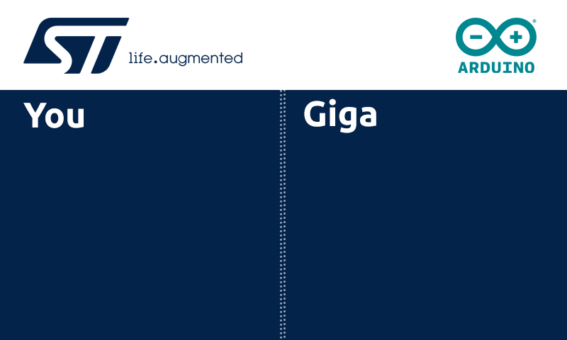
We display on the screen a background and the signs to play SHIFUMI (scissor, paper, and rock). You can download these images:
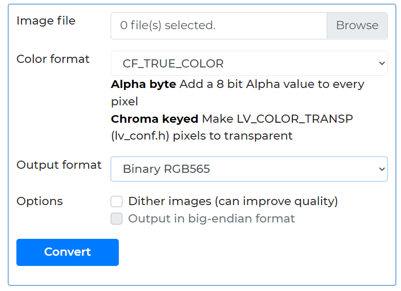
We also need to convert them to bin files using this website:
- Online image converter - BMP, JPG or PNG to C array or binary | LVGL
- Select the images.
- Change the output format to binary RGB565
- Click convert
Then:
- Get all the binary images and copy them in the project folder. You can create a folder named images, for example, and put them in it.
- In the code, update the image path. You may need to add the full path of the images
4.4. NanoEdge library usage
Concerning the use of NanoEdge AI Library, it is really simple:
- We use the function neai_classification_init(knowledge) in setup() to load the model with the knowledge acquired during the benchmark.
- We use the function neai_classification(neai_buffer, output_buffer, &neai_class) to make the detection. This function takes as input three variables that we created as well:
- float neai_buffer[64]: the input data for the detection, which are the ToF data
- float output_buffer[CLASS_NUMBER]: An output array of size 4 containing the probability for the input signal to be part of each class
- uint16_t neai_class = 0: the variable we use to get the class detected. It corresponds to the class with the highest probability.
That’s it!
5. Demonstration setup
If you want to reproduce this demo setup, here are the resources used:
- 4x Brackets 20.stl: https://www.printables.com/model/113989-corner-bracket-optimized-for-3d-printing/files
- M3 nylon 12mm screws and M3 nylon nuts
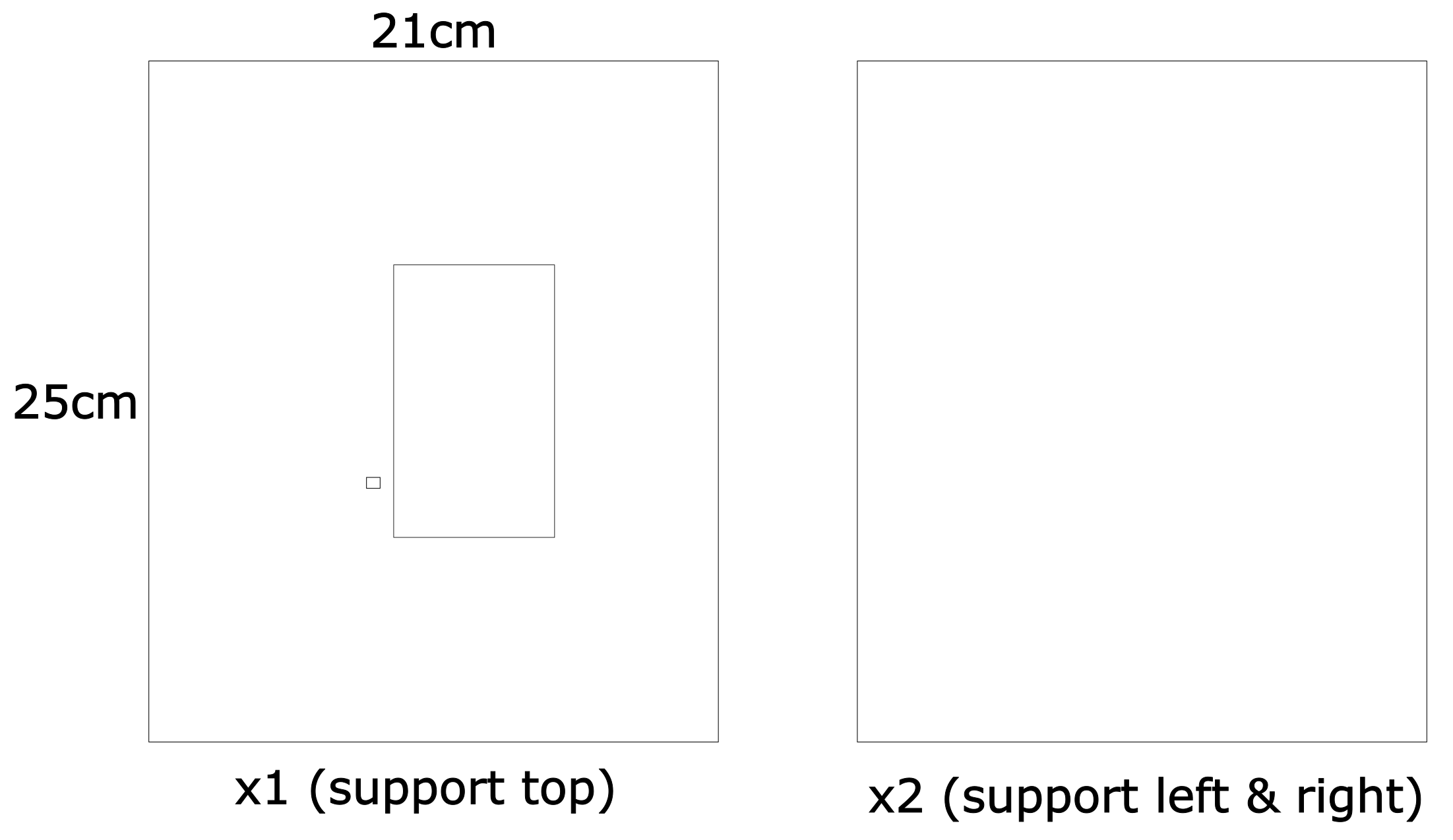
- Support:
