1. STM32WB dual core
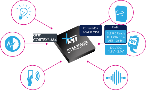
The STM32WB combines an Arm® Cortex®-M4 for the application, plus a 2.4 GHz radio subsystem and an Arm® Cortex®-M0+ processor running the firmware upgrade service (FUS) and the wireless stack .
| STM32WB dual core |
|---|
All the code running on Arm® Cortex®-M0+ (CPU2) is delivered as encrypted binary, and it is necessary to upgrade the wireless stack before developing a project on the application side.
- Black box for customer perspective
All the code running on the Arm® Cortex®-M4 (CPU1) is delivered as source code.
The STM32WB is pre-loaded with root security system (FUS) firmware necessary to authenticate the selected wireless stack (binary encrypted format) loaded by the customer on st.com.
| STM32WB memory mapping |
|---|
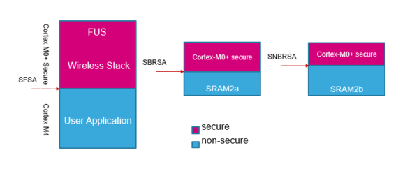
Cortex®-M0+ security protects the upper parts of the flash and SRAM2 memories. The sizes of the areas are automatically set during wireless stack install or update:
- Secure flash start address (SFSA) is the lower boundary of protected flash memory. It is aligned on 4 Kbytes(WB5x) or 2 Kbytes(WB1x) granularity.
- For STM32WB5x and STM32WB3x families:
- Secure backup RAM start address (SBRSA) and secure non-backup RAM start address (SNBRSA) are the lower address of protected parts of the SRAM2a and SRAM2b memories respectively. The size can be set with a granularity of 1 Kbytes.
- Backup SRAM2a can be used to store data when system is in standby mode.
2. System and Memory Overview
2.1. System Architecture
2.2. Memory System
3. Radio System
4. General-purpose I/Os (GPIOs)
5. USART/UART
6. IPCC
7. References


