| Coming soon |
1. Bluetooth® Low Energy security overview
1.1. Security features
The Bluetooth® Low Energy security model includes five distinct security features:
- Pairing: process for creating one or more shared secret keys.
- Bonding: the act of storing the keys created during pairing for use in subsequent connections in order to form a trusted device pair.
- Device authentication: verification that the two devices have the same keys.
- Encryption: message confidentiality.
- Message integrity: protects against message forgeries. (4 bytes Message Integrity Check MIC)
1.2. Pairing process
Bluetooth® Low Energy uses 2 pairing methods:
- LE Legacy Pairing : Introduced in Bluetooth® Low Energy standard v4.0 and v4.1 and based on AES-CCM encryption.
- LE Secure Connection : Introduced in Bluetooth® Low Energy standard v4.2 which upgrade LE Legacy pairing to utilize FIPS-approved algorithms (AES-CMAC and P-256 elliptic curve) on the LE physical transport.
The pairing is composed of three phases:
- Phase 1: Pairing Feature Exchange
- Phase 2 (LE legacy pairing): Short Term Key (STK) Generation
- Phase 2 (LE Secure Connections): Long Term Key (LTK) Generation
- Phase 3: Transport Specific Key Distribution
| Pairing flowchart |
|---|
1.2.1. Phase 1: Pairing Feature Exchange
The Pairing Feature Exchange phase is used to exchange device capabilities to the peer device and vice versa. The information exchange are the IO capabilities, OOB authentication data availability, authentication requirements, key size. This exchange is done through the Pairing Request and Pairing Response packet and allow to determine the key generation method used in Phase 2.
Note: all data being exchanged during this phase is unencrypted.
| Pairing Feature Exchange |
|---|
1.2.2. Phase 2: Key Generation
The Key Generation phase is specific for each pairing methods. According to the capabilities exchange in phase 1, the key generation method is one of the following method:
- Just Works
- Passkey Entry
- Out of Band (OOB)
- Numeric Comparison: Only for LE Secure Connections
The key generation methods depend of IO capabilities values exchange in phase 1:
| Mapping of IO capabilities to key generation method |
|---|
In the table above, authenticated means MITM protection required and unauthenticated means MITM protection is not required.
1.2.2.1. LE Legacy Pairing - Phase 2: Short Term Key (STK) Generation
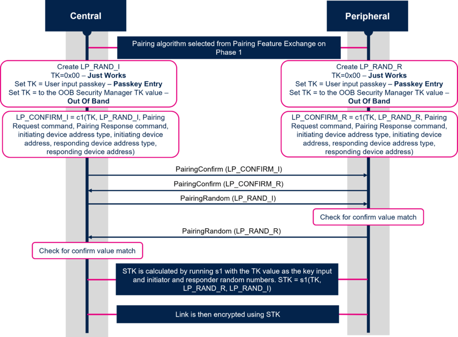
For LE Legacy Pairing, the phase 2 is called Short Term Key (STK) Generation. This methods uses and generates 2 keys:
1. Temporary Key (TK): a 128-bit temporary key used in the pairing process which is used to generate STK.
2. Short Term Key (STK): a 128-bit temporary key used to encrypt a connection following pairing.
The diagram below describes each step of the Short Term Key (STK) Generation:
| Short Term Key (STK) Generation |
|---|
As shown in the diagram above the TK is set to different values depending of key generation method used:
- Just Works: TK is set to 0
- Passkey Entry: TK is equal to passkey + 0 padded (MSB)
- OOB: TK is equal to OOB data
1.2.2.2. LE Secure Connections - Phase 2: Long Term Key (LTK) Generation
For LE Secure Connections, the phase 2 is called Long Term Key (LTK) Generation. This method uses and generates 1 key:
1. Long Term Key (LTK): a 128-bit key used to encrypt the connection following pairing and subsequent connections.
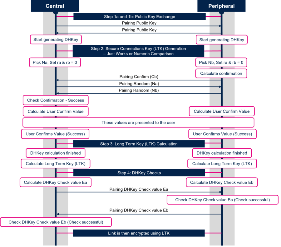
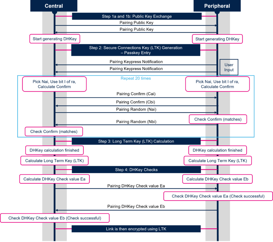
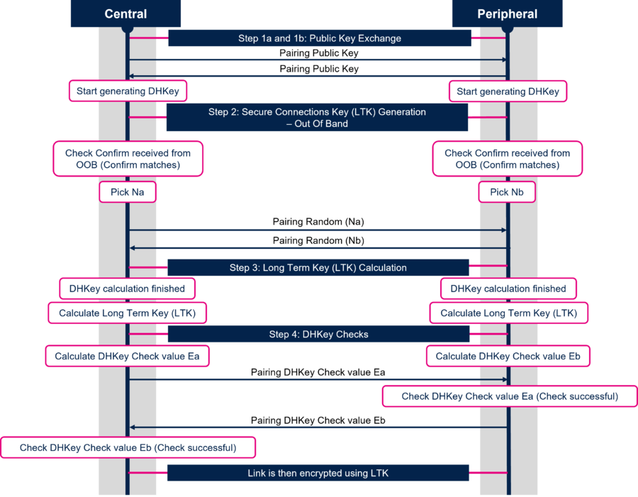
When LE Secure Connections is used the Long Term Key (LTK) Generation is split in four steps:
- Step 1 : Public Key Exchange
- Step 2 : Secure Connections Key (LTK) Generation - Authentication stage 1 : Specific for each key generation method
- Step 3 : Long Term Key (LTK) Calculation
- Step 4 : DHKey Checks - Authentication stage 2
The diagram below describes each step of the Long Term Key (LTK) Generation when Just Works or Numeric Comparison method is used:
| Long Term Key (LTK) Generation for Just Works and Numeric Comparison method |
|---|
Note: The sequence for Just Works is identical to that of Numeric Comparison with the exception that the Host will not show the numbers to the user.
The diagram below describes each step of the Long Term Key (LTK) Generation when Passkey Entry method is used:
| Long Term Key (LTK) Generation for Passkey Entry method |
|---|
Note: Passkey Entry may prolong pairing experience because of the time required to execute 20 repetitions over SMP.
The diagram below describes each step of the Long Term Key (LTK) Generation when OOB method is used:
| Long Term Key (LTK) Generation for Passkey Entry method |
|---|
1.2.3. Phase 3: Transport Specific Key Distribution
After the key generation, the link is encrypted and the transport specific keys are distributed. The following diagram shows s an example of all keys and values being distributed by Central and Peripheral:
| Transport Specific Key Distribution |
|---|
1.3. LE Security Mode
The security requirements of a device, a service or a service request are expressed in terms of a security mode and security level. Each service or service request may have its own security requirement. The device may also have a security requirement. A physical connection between two devices shall operate in only one security mode.
STM32WB-WBA support LE Security Mode 1 which have the following security levels:
1. No security (No authentication and no encryption)
2. Unauthenticated pairing with encryption (no MITM protection)
3. Authenticated pairing with encryption (MITM protection)
4. Authenticated LE Secure Connections pairing with encryption using a 128-bit strength encryption key.
2. How to setup the pairing in your application
2.1. Parameters and commands overview
Two commands need to be send during the initialization of the device (e.g when the device is not in connected state):
- aci_gap_set_io_capability : Sets the IO capabilities of the device:
| aci_gap_set_io_capability command |
|---|
- aci_gap_set_authentication_requirement : Sets the authentication requirements for the device:
| aci_gap_set_authentication_requirement command |
|---|
All the parameters describes above are define in app_conf.h file:
/**
 * Define BD_ADDR type: define proper address. Can only be GAP_PUBLIC_ADDR (0x00) or GAP_STATIC_RANDOM_ADDR (0x01)
 */
#define CFG_IDENTITY_ADDRESS              GAP_PUBLIC_ADDR
**
 * Define IO Authentication
 */
#define CFG_BONDING_MODE                 (1)
#define CFG_FIXED_PIN                    (111111)
#define CFG_USED_FIXED_PIN               (0)
#define CFG_ENCRYPTION_KEY_SIZE_MAX      (16)
#define CFG_ENCRYPTION_KEY_SIZE_MIN      (8)

/**
 * Define IO capabilities
 */
#define CFG_IO_CAPABILITY_DISPLAY_ONLY        (0x00)
#define CFG_IO_CAPABILITY_DISPLAY_YES_NO      (0x01)
#define CFG_IO_CAPABILITY_KEYBOARD_ONLY       (0x02)
#define CFG_IO_CAPABILITY_NO_INPUT_NO_OUTPUT  (0x03)
#define CFG_IO_CAPABILITY_KEYBOARD_DISPLAY    (0x04)

#define CFG_IO_CAPABILITY                     CFG_IO_CAPABILITY_DISPLAY_YES_NO

/**
 * Define MITM modes
 */
#define CFG_MITM_PROTECTION_NOT_REQUIRED      (0x00)
#define CFG_MITM_PROTECTION_REQUIRED          (0x01)

#define CFG_MITM_PROTECTION                   CFG_MITM_PROTECTION_REQUIRED

/**
 * Define Secure Connections Support
 */
#define CFG_SECURE_NOT_SUPPORTED              (0x00)
#define CFG_SECURE_OPTIONAL                   (0x01)
#define CFG_SECURE_MANDATORY                  (0x02)

#define CFG_SC_SUPPORT                        CFG_SECURE_OPTIONAL

/**
 * Define Keypress Notification Support
 */
#define CFG_KEYPRESS_NOT_SUPPORTED            (0x00)
#define CFG_KEYPRESS_SUPPORTED                (0x01)

#define CFG_KEYPRESS_NOTIFICATION_SUPPORT     CFG_KEYPRESS_NOT_SUPPORTED
Once Bluetooth® LE link is established, the pairing procedure can be starts by:
- the central using aci_gap_send_pairing_req command:
| aci_gap_send_pairing_req command |
|---|
- the peripheral using aci_gap_peripheral_security_req command:
| aci_gap_peripheral_security_req command |
|---|
2.2. Legacy pairing use cases
2.2.1. Passkey Entry using fixed pin
The initialization commands are send with the following parameters to perform LE Legacy Pairing Passkey Entry using fixed pin:
aci_gap_set_io_capability(0x00 - IO_CAP_DISPLAY_ONLY)
aci_gap_set_authentication_req (1, - bonding mode
                             1, - MITM
                             0, - SC pairing not supported
                             0, - keypress notification not supported
                             8, - min_encryption_key_size
                             16, - max_encryption_key_size
                             0, - use a fixed pin
                             111111, - fixed pin (used)
                             0 - identity address type)
Once the device is initialized, the advertising is started. Then, using ST BLE Toolbox smartphone application, the connection is established and a pairing request is sent with the pin code define into the application (here 111111) to established pairing between the 2 devices:
| Legacy pairinp: Passkey Entry using fixed pin |
|---|
2.2.2. Passkey Entry without using fixed pin
The initialization commands are send with the following parameters to perform LE Legacy Pairing Passkey Entry without using fixed pin:
aci_gap_set_io_capability(0x00 - IO_CAP_DISPLAY_ONLY)
aci_gap_set_authentication_req (1, - bonding mode
                             1, - MITM
                             0, - SC pairing not supported
                             0, - keypress notification not supported
                             8, - min_encryption_key_size
                             16, - max_encryption_key_size
                             1, - do not use a fixed pin
                             111111, - fixed pin (unused)
                             0 - identity address type)
Once the device is initialized, the advertising is started. Then, using ST BLE Toolbox smartphone application, the connection is established and a pairing request is sent with a pin code (here 123456). On server side, the ACI_GAP_PASS_KEY_REQ_EVENT event is generated and the application respond using aci_gap_pass_key_resp command with the same pin in parameter to established pairing between the 2 devices:
| Legacy pairing: Passkey Entry without using fixed pin |
|---|
2.3. Secure Connections use cases
For Passkey Entry method, it's the same flow than for LE Legacy Pairing, the only thing to change is the value of SC_Support parameter of aci_gap_set_authentication_requirement command to support secure connections (e.g 0x01: Secure Connections Pairing supported but optional 0x02: Secure Connections Pairing supported and mandatory (SC Only Mode)).
2.3.1. Numeric Comparison
The initialization commands are send with the following parameters to perform Secure Connections with numeric comparison method:
aci_gap_set_io_capability(0x04 - IO_CAP_KEYBOARD_DISPLAY)
aci_gap_set_authentication_req (1, - bonding mode
                             1, - MITM
                             2, - Secure Connections Pairing supported and mandatory
                             0, - keypress notification not supported
                             8, - min_encryption_key_size
                             16, - max_encryption_key_size
                             0, -  Use a fixed pin
                             111111, - fixed pin (not used)
                             0 - identity address type)
| Secure Connection pairing |
|---|
3. How to decrypt the traffic
4. Additional information - BLE characteristics and security permissions
4.1. STM32WB - BLE GATT characteristic
When a characteristic is created (aci_gatt_add_char), following security permissions could be given:
- 0x00: none
- 0x01: AUTHEN_READ (need authentication to read)
- 0x02: AUTHOR_READ (need authorization to read)
- 0x04: ENCRY_READ (need encryption to read)
- 0x08: AUTHEN_WRITE (need authentication to write)
- 0x10: AUTHOR_WRITE (need authorization to write)
- 0x20: ENCRY_WRITE (need encryption to write)
4.1.1. READ and WRITE properties
A characteristic is created with properties READ and WRITE
4.2. AUTHEN_READ and AUTHEN_WRITE security permissions
After the discovery of services and characteristics, if the client tries to read or write this characteristic, an error is returned (ACI_GATT_ERROR_RESP_EVENT) with error_code=0x05 (insufficient authentication)
Set MITM (in aci_gap_set_authentication_requirement) is necessary and need of start pairing to be able to read/write the characteristic with 'need authentication' permissions.
Security permission 'need authentication' is more restrictive than 'need encryption'.
4.3. ENCRY_READ and ENCRY_WRITE security permissions
After the discovery of service and characteristic, if the client tries to read or write this characteristic, an error is returned (ACI_GATT_ERROR_RESP_EVENT) with error_code=0x0F (insufficient encryption)
If the devices are paired and encryption is started, read and write operations can be done. No need to set MITM and need of starting pairing to be able to read/write the characteristic with 'need encryption' permissions
4.4. AUTHOR_READ and AUTHOR_WRITE security permissions
The way to use characteristic with 'need authorization' permissions: after the connection_complete_event, the server sends the command aci_gap_set_authorization_requirement (for current connection handle) the master initiates pairing. When the pairing is complete, ACI_GAP_AUTHORIZATION_REQ_EVENT is generated on server side which sends aci_gap_authorization_resp(conn_handle, authorize) then the client can read/write the characteristic.


