1. Heart Rate Profile Presentation
Heart Rate Profile (HRP) [1] is a Generic Attribute Profile (GATT) based low energy profile defined by the Bluetooth® Special Interest Group[2]
The HRP, widely used in fitness applications, defines the communication between a GATT-server of a Heart Rate Sensor device, such as a wrist band, and a GATT-client Collector device, such as a smartphone or tablet.
Heart Rate Sensor is the device that measures heart rate data and other information, it can be defined as a GAP peripheral and GATT server implemented with the Heart Rate Service [3]
This wiki page is the description of the Heart Rate Sensor project provided within the STM32CubeWB MCU Package[4]
| Bluetooth® LE Heart Rate profile overview |
|---|
2. Heart Rate Sensor Example
2.1. Requirements
2.1.1. Software and System requirements
Software required are the following:
minimum IDEs version:
- IAR Embedded Workbench for ARM (EWARM) toolchain V8.20.2
- RealView Microcontroller Development Kit (MDK-ARM) toolchain V5.31
- STM32CubeIDE toolchain V1.7.0 [5].
Programmer:
- STM32CubeProgrammer[6] : To flash the board with an already generated binary
2.1.2. Hardware requirements
A Nucleo board[7], a STM32WB USB dongle[7], or a STM32WB Discovery Kit[8] is necessary to install the application.
| Hardware platforms illustration |
|---|
|
|
Plus a smartphone with ST BLE Sensor application (for Android[9], or iOS[10]).
2.1.3. Project Directory
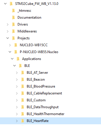
The "BLE_HeartRate" application is available by downloading STM32CubeWB MCU Package[11].
| Heart Rate project directory |
|---|
2.2. Project Description
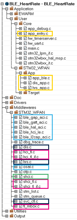
2.2.1. Structure
Software project structure with the most important parts :
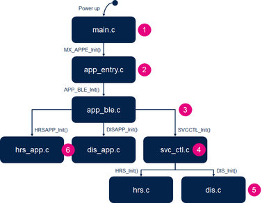
2.2.2. Application Initialization
The different steps of application initialization are described bellow :
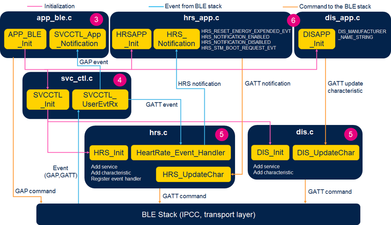
2.2.3. GAP & GATT Initialization & Interaction
Interaction between Middleware and User Application is described in the following illustration. lionel to explain...
| Heart Rate project architecture |
|---|
2.3. Build and Install
Follow steps described in Bluetooth® LE Build and Install Application page, applying it for BLE_HeartRate project.
2.4. Handle
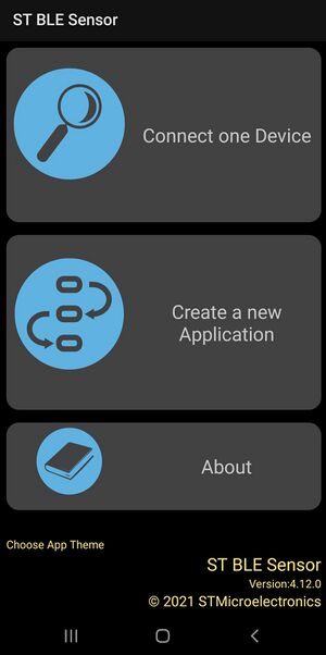
Once the BLE Heart Rate application installed on the STM32WB platform, launch the ST BLE Sensor smartphone application.
Click on Connect one Device interface:
| Heart Rate application interface 1 |
|---|
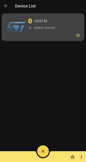
Your device should be visible from this interface, connect to it:
| Heart Rate application interface 2 |
|---|
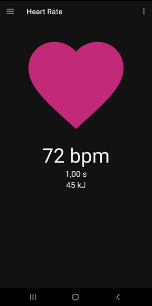
Now bpm measurement is displayed in real time.
| Heart Rate application interface 3 |
|---|
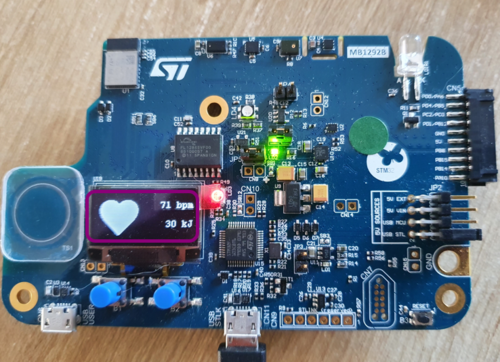
With Discovery Kit Platform, the Heart Rate is also visible from the board LCD screen, and Heart pulse is illustrated:
| Heart Rate on DK illustration |
|---|
3. References
- ↑ Heart Rate profile specification
- ↑ Bluetooth® SIG
- ↑ Heart Rate service specification
- ↑ STM32CubeWB MCU Package
- ↑ STM32CubeIDE
- ↑ STM32CubeProgrammer Software
- ↑ 7.0 7.1 P-NUCLEO-WB55 package
- ↑ STM32WB5MM-DK board
- ↑ ST BLE Sensor Android application
- ↑ ST BLE Sensor iOSapplication
- ↑ STM32CubeWB MCU Package


