This article is describing how to allocate more internal Flash memory to the Cortex M7 of the STM32H747 Discovery board.
The STM32H747 microcontroller is a dual-core Cortex M7 + Cortex M4 with 2 MB of internal Flash.
By default, half of the Flash is allocated to the Cortex M7 and the other half to the Cortex M4.
When using STM32Cube.AI to generate STM32 code from a pre-trained neural network, model weights are stored by default in internal Flash. To run models exceeding 1MB of weights, it is required to allocate more Flash to the Cortex M7 (or on the contrary to the Cortex M4 depending on the selected core).
This article show how to modify the internal Flash memory allocation. The tutorial is showing how to allocate 1984 kB of Flash to the Cortex M7 and the rest of the Flash (64 kB) to the Cortex M4.
1. Prerequisites
1.1. Hardware
- STM32H747I-DISCO
- A Micro-USB to USB cables
1.2. Software
2. Modify the boot addresses
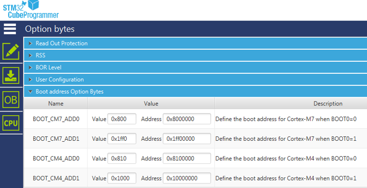
The Cortex M7 is booting by default at the address 0x08000000 whereas the Cortex M4 boot at the address 0x08100000. This should be modified:
- Connect the board to the PC thanks to the USB cable using the USB STLink connector
- Open the STM32CubeProgrammer tool and connect to the board.
- Click on OB (Option Bytes) to modify the BOOT_CM4_ADD0
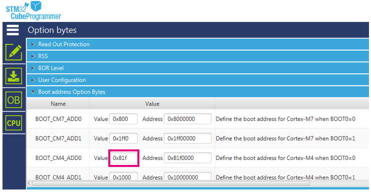
- Modify the CM4 boot address bytes to 0x81F0000 address instead of 0x8100000. You simply have to modify the value from 0x810 to 8x1f.
The initial configuration is as below:
The final configuration shall be as below:
2.1. Generate the code with STM32Cube.AI
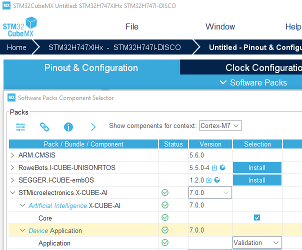
Generate the project for your model as usual with STM32Cube.AI. Do not use the one click "Validation on target" feature from the UI, it will take the default memory allocation. Instead use the Project Manager. Make sure to select the "Device Application" in the menu when selecting the X-CUBE-AI software package, for instance the Validation application as below:
Then use the Generate Project feature (make sure to enter a name for your project as well as selecting your IDE in the Project Manager table).
2.2. Modify the linker scripts
Once the project has been generated, the linker script shall reflect the new memory allocation. Below is detailed the modification for STM32Cube IDE linker scripts: Cortex M7 Flash linker script stm32h747xi_flash_cm7.ld
/* Memories definition */
MEMORY
{
  RAM    (xrw)   : ORIGIN = 0x24000000, LENGTH =  512K    /* Memory is divided. Actual start is 0x24000000 and actual length is 512K */
  FLASH   (rx)   : ORIGIN = 0x08000000, LENGTH = 1984K    /* Memory is divided. Actual start is 0x08000000 and actual length is 1984K */
 …
Cortex M7 RAM linker script stm32h747xi_ram_cm7.ld :
/* Memories definition */
MEMORY
{
  RAM    (xrw)   : ORIGIN = 0x24000000, LENGTH =  512K    /* Memory is divided. Actual start is 0x24000000 and actual length is 512K */
  FLASH   (rx)   : ORIGIN = 0x08000000, LENGTH = 1984K    /* Memory is divided. Actual start is 0x8000000 and actual length is 1984K */
….
Cortex M4 Flash linker script stm32h747xi_flash_cm4.ld:
/* Specify the memory areas */
MEMORY
{
FLASH (rx)     : ORIGIN = 0x081F0000, LENGTH = 64K
RAM (xrw)      : ORIGIN = 0x10000000, LENGTH = 288K
}
You can then build the application and load it to the STM32 target using the IDE or STM32CubeProgrammer.
2.3. Run the validation on target from STM32Cube.AI
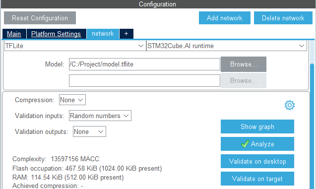
Once the Validation application has been uploaded in the STM32 target with the board connected to the PC through the STLink USB connector, the firmware will start and wait for commands from the PC. On the configuration panel of STM32Cube.AI, you can then launch the "Validation on target". Click on the corresponding button:
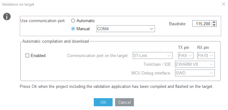
The following pop-up window will open, select the COM port manually or let the plugin do it automatically. Do not enable the "Automatic compilation and download" option otherwise the firmware will be replaced by the default one without the new Flash allocation":
You can then click on "Ok" to run the validation on target as usual.
