1. BLE Power Consumption Profile
The BLE Power Consumption Profile is a Generic Attribute Profile (GATT) based low-energy profile defined by STMicroelectronics with proprietary UUIDs(16 bits).
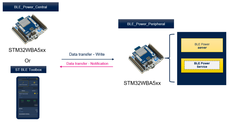
Provided in Both applications BLE_Power_Peripheral and BLE_Power_Central on STM32WBA hardware boards it offer users a fully flexible applications for power measurement purpose.
- The BLE Power Peripheral
-
- In Advertising state : Used to measure power consumption with different possible configurations (Advertising type, Advertising interval,…)
- In Connected state : Used to measure power consumption in connected Idle or with data transfer.
- The BLE Power Central
-
- In Connected state : Used to measure power consumption in connected Idle or with data transfer.
| Bluetooth® LE Power Profile & STM32WBA |
|---|
Combining the ability to run multiple application scenarios and measuring its power consumption, the BLE Power Applications offer an overview of the software/Hardware configurations and recommendations to test and reach the best power consumption.
| STM32CubeMonitor-Power & STM32WBA Power Consumption |
|---|
2. STM32WBA BLE Power application requirements
2.1. STM32WBA Hardware board
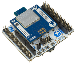
In order to measure the STM32WBA power consumption the NUCLEO-WBA5xx board is the best candidate to run this setup due to its PCB optimization, reduced components and low cost.
- Depending on the targeted power consumption purpose one or two NUCLEO-WBA5xx hardware boards are required.
| NUCLEO-WBA5xx Hardware Board. |
|---|
- Measuring the BLE Power peripheral in Advertising state, only one Hardware board is required
- Measuring the BLE Power peripheral in Connected state, only one Hardware board is required if connected to smartphone via ST BLE toolbox. Or a second Hardware board is optional to connect to BLE Power Central.
- Measuring the BLE Power Central in Connected state ,two Hardware board are required. One for the Central and another one for the Peripheral.
2.2. Power Measurement Setup : Software Requirements
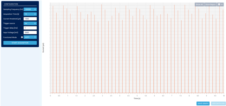
In order to measure the NUCLEO-WBA5xx Power consumption we will use the ,STM32CubeMonitor-Power (create link to STM32CubeMonPwr) For more details on how to use it please refer to the User Manual UM2202(create link)
2.3. Power Measurement Setup : Hardware Requirements
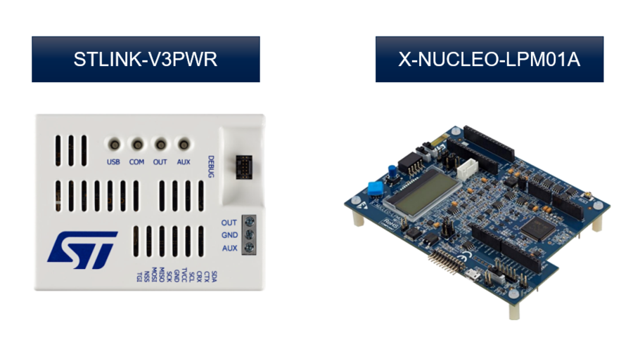
For the Power measurement, STM32CubeMonitor-Power require to connect on one of the following Hardware boards the X-NUCLEO-LPM01A, the STLINK-V3PWR or the energy meter of the STM32L562E-DK Discovery. For the following topic we will focus on the STLINK-V3PWR.
| Power Consumption Hardware Boards |
|---|
Power Measurement setup overview:
| Power Consumption Setup |
|---|
Connect the Stlink-V3PWR GND to the STM32WBA5xx GND. Remove STM32WBA5xx JP2 and Connect the STLINK-V3PWR OUT to the STM32WBA5xx JP2 pin 2:
| Power Consumption : NUCLEO-WBA5xx Connection |
|---|
3. BLE POWER Application presentation
3.1. BLE POWER Application setup overview
The BLE Power Application is dedicated for Power consumption measurements. In order to avoid extra power consumption, the application have 2 phases:
- A Setup phase : application not in low power phase dedicated for configuration , all buttons are active for configuration
- A Power Measurement phase : application enter low power phase , all GPIOs are disabled
Application Trace is by default disabled to avoid extra power consumption.
| BLE Power Application Overview |
|---|
Note:
- During Setup Time, STM32WBA5xx STlink must be powered in order to use buttons.
- By default setup time is 10seconds duration, but it can be modified in app_conf.h "Setup_Time " define variable.
3.2. BLE Peripheral Power, possible configuration and power measurement
In the following chapter we will discover the application features and possible configurations. The application offers a default configuration. In order to align with user's application, listed defines in the following chapter can be modified depending on the needs.
3.2.1. Application general parameters
The following table defines the application general parameters.
| BLE Peripheral Power General Parameters(1) | ||||||||||||||||||||
|---|---|---|---|---|---|---|---|---|---|---|---|---|---|---|---|---|---|---|---|---|
|
(1) defines are available in app_conf.h
(2) GPIOs configured in analog mode to avoid Schmitt trigger's extra power consumption.
3.2.2. Advertising Power measurement
After Reset the BLE Power Peripheral start Advertising data packets. The following table summarize the application possible configuration during advertising/not connected state.
| BLE Peripheral Advertising configuration(1) | ||||||||||||||||
|---|---|---|---|---|---|---|---|---|---|---|---|---|---|---|---|---|
|
(1)variables default values can be modified under app_conf.h
| Advertising Power Consumption |
|---|
Recommendations: Increasing the Advertising interval reduces the power consumption for a better battery life.
Zooming into the run mode activity shows the following graph: Note that Low Power mode state here is Standby.
| Connectable Advertising power consumption in running phase (Exit from Standby) |
|---|
Application configuration impact on power consumption and recommendation: Depending on the application requirement we can change some parameters for power consumption simulation. Here an example of:
- Low power mode : Stop mode
- Advertising Type : ADV_NONCONN_IND
| Non-Connectable Advertising power consumption in running phase (Exit from Stop) |
|---|
Notes :
- Depending on the application requirement stop mode have a higher power consumption during application low power mode phase than Standby but a faster wakeup.
- Lower advertising packet size reduce the ADV TX channels power consumption.
- During ADV_NONCONN_IND ADV RX channels are OFF.
3.2.3. Connected mode Power measurement
Connection to the Peripheral can be either be made using the BLE Toolbox mobile app or the BLE Power Central via a second STM32 Hardware board.In this chapter we will focus on BLE Toolbox mobile app connection.
Open your ST BLE ToolBox and start scanning for the application "PWR". Once scanned, press CONNECT to establish connection with the BLE Power Peripheral.
| BLE ToolBox connection to PWR Peripheral |
|---|
Idle Connection
When connection is established by default the PHY selected is 1M, Empty LE packet are sent from the Central to maintain the connection.
The delay between Empty LE packet is defined by connection interval.
| Default Idle connection configuration | ||||||||||||||||
|---|---|---|---|---|---|---|---|---|---|---|---|---|---|---|---|---|
|
Just like the Advertising interval, the connection interval have impact on the application power consumption. The following Figure shows the impact on power consumption by pressing B3 switching the connection interval from 50ms to 200ms.
| Switching Connection Interval |
|---|
Data transfer Connection
In order to Enable Data transfer , Notification must be enabled in the BLE Toolbox application.
Once done Pressing button 1 to toggle data transfer each 1s.
| Enabling Data transfer |
|---|
3.3. BLE Central Power, possible configuration and power measurement
In the following chapter we will discover the application features and possible configurations. The application offers a default configuration. In order to align with user's application, listed defines in the following chapter can be modified depending on the needs.
3.3.1. Application general parameters
The following table defines the application general parameters.
| BLE Peripheral Power General Parameters(1) | ||||||||||||||||||||
|---|---|---|---|---|---|---|---|---|---|---|---|---|---|---|---|---|---|---|---|---|
|
4. STM32WBA P2P Server & P2P Client examples description
4.1. Project directory
The "BLE_p2pServer" & "BLE_p2pClient"applications are available by downloading STM32CubeWBA MCU Package[1].
Refer to How to Build a Bluetooth® LE project wiki page for project directory information.
4.2. Project description
4.2.1. Structure
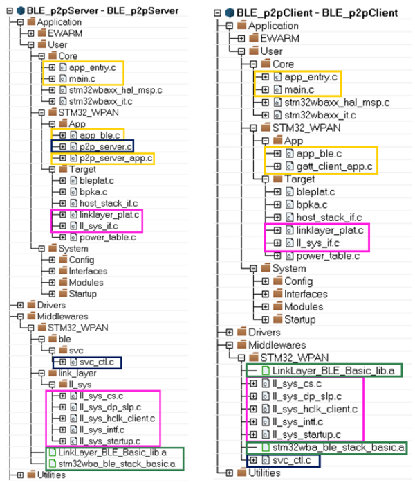
Software project structure with the most important parts:
| P2P Server / Client project structure |
|---|
|
WARNING: Do not modify the files in Middlewares folder |
4.2.2. Application initialization
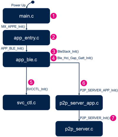
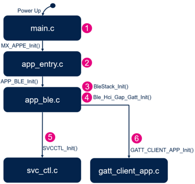
The different steps of the application initialization are described below:
| P2P Server project initialization |
|---|
| P2P Client project initialization |
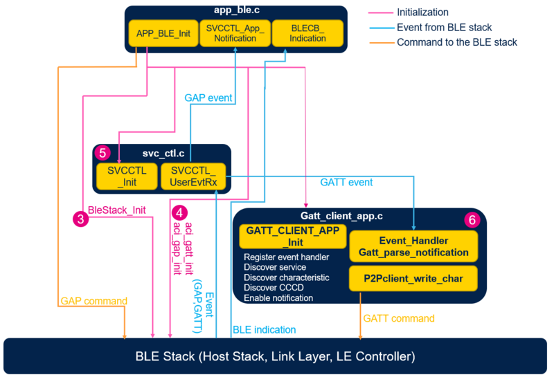
4.2.3. GAP and GATT initialization and interaction
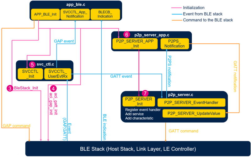
P2P Server:
| P2P Server software module interaction |
|---|
and ![]() The Bluetooth LE P2P Server application initialization is done within app_ble.c
The Bluetooth LE P2P Server application initialization is done within app_ble.c
- Initialize the Bluetooth® Low Energy stack - initialize the device as peripheral - configure and start advertising: ADV parameters, local name, UUID - APP_BLE_init()
- Call the services controller initialization SVCCTL_Init() - svc_ctl.c
- Manage the GAP event - SVCCTL_App_Notification() - svc_ctl.c
- HCI_LE_CONNECTION_COMPLETE - provides information of the connection interval, slave latency, supervision timeout
- HCI_LE_CONNECTION_UPDATE_COMPLETE- provides the new information of the connection
- HCI_DISCONNECTION_COMPLETE - informs the application about the link disconnection and the reason
The Services management is done by the service controller, svc_ctl.c
- Initialize the number of registered handler - SVCCTL_Init()
- Manage events - SVCCTL_UserEvtRx()- from the Bluetooth® Low Energy Host Stack and redirect them to the gap event handler - SVCCTL_App_Notification()
The application level of the P2P Server is done with p2p_server_app.c:
- Initialization of the services:
- P2P Server Service - P2P_SERVER_Init() - p2p_server.c
- Initialization of the context of the application
- Receive notification from the P2P Server Service - P2P_SERVER_Notification()
- When P2P_SERVER_LED_C_WRITE_NO_RESP_EVT event is received from the P2P Client, the blue LED is toggled.
- P2P_SERVER_Switch_c_SendNotification() function is called on Button B1 press, to notify the P2P Client:
- P2P_SERVER_UpdateValue() is called with the notification data - p2p_server.c
The Custom P2P Server Service p2p_server.c manages the specification of the service:
- Service Init - P2P_SERVER_Init()
- Register P2P Server Event Handle to Service Controller - SVCCTL_RegisterSvcHandler();
- Initialize Service UUID – add P2P Server service as Primary services
- Initialize LED_C characteristic
- Initialize SWITCH_C characteristic
- Manage the GATT event from Bluetooth® Low Energy Stack - P2P_SERVER_EventHandler()
- ACI_GATT_ATTRIBUTE_MODIFIED_VSEVT_CODE
- Reception of an attribute modification - LED C Value : ON or OFF Indication
- Notify application of the Measurement Notification - P2P_SERVER_Notification(P2P_SERVER_LED_C_WRITE_NO_RESP_EVT)
- Reception of an attribute modification - LED C Value : ON or OFF Indication
- ACI_GATT_ATTRIBUTE_MODIFIED_VSEVT_CODE
P2P Client:
| P2P Client software module interaction |
|---|
and ![]() The Bluetooth LE P2P Client application initialization is done within app_ble.c
The Bluetooth LE P2P Client application initialization is done within app_ble.c
- Initialize the Bluetooth® Low Energy stack - initialize the device as peripheral - configure and start advertising: ADV parameters, local name, UUID - APP_BLE_init()
- Call the services controller initialization SVCCTL_Init() - svc_ctl.c
- Manage the GAP event - SVCCTL_App_Notification() - svc_ctl.c
- HCI_LE_CONNECTION_COMPLETE - provides information of the connection interval, slave latency, supervision timeout
- HCI_LE_CONNECTION_UPDATE_COMPLETE- provides the new information of the connection
- HCI_DISCONNECTION_COMPLETE - informs the application about the link disconnection and the reason
The Services management is done by the service controller, svc_ctl.c
- Initialize the number of registered handler - SVCCTL_Init()
- Manage events - SVCCTL_UserEvtRx()- from the Bluetooth® Low Energy Host Stack and redirect them to the gap event handler - SVCCTL_App_Notification()
The application level of the P2P Client is done with gatt_client_app.c:
- Initialization of the application context
- Register Event Handler to Bluetooth® Low Energy Controller - SVCCTL_RegisterCltHandler();
- Initialize LED data level and selection
- Manage the GATT event from Bluetooth® Low Energy Stack - gatt_parse_notification()
- ACI_GATT_NOTIFICATION_VSEVT_CODE
- When the notification event is received from the P2P Server, the blue LED is toggled - gatt_Notification()
- ACI_GATT_NOTIFICATION_VSEVT_CODE
- Write characteristic to P2P Server (LED toggling) - P2Pclient_write_char() - by pressing Button B1 while connected.
4.3. How to use the Bluetooth® Low Energy P2P Server and P2P Client applications
P2P Server VS Smartphone
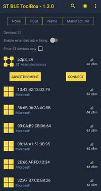
Once the BLE P2P Server application is installed on the STM32WBA platform, launch ST BLE ToolBox smartphone application.
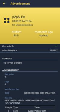
Then, scan and connect the device called p2pS_XX (where XX is replaced by the last byte of the BD address) to the application.
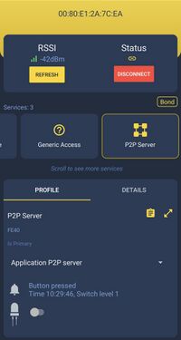
Once the Bluetooth® LE connection is established and the notification enabled by the smartphone (by clicking on P2P Server icon):
- LED_C value can be modified by clicking on the LED button on smartphone interface, the blue LED of the Nucleo board is switched On/Off accordingly.
- Pressing Button B1 on the board while connected send a SWITCH_C notification to the smartphone and the switch level is updated on the smartphone interface.
P2P Server VS P2P Client
At least two nucleo platforms are required, one flashed with the BLE P2P Server application and one with the BLE P2P Client application.
- On P2P Client side:
- Pressing Button B1 on P2P Client platform while not connected, start a scan procedure, and connection is done if a P2P Server platform is found.
- Pressing Button B1 on P2P Client platform while connected, send a GATT event to the P2P Server platform in order to switch On/Off server blue LED.
- On P2P Server side:
- Pressing Button B1 on P2P Server side while connected send a SWITCH_C notification to the P2P Client platform and toggle the blue LED on client side.
- Pressing Button B2 on P2P Server side while connected, start a new advertising in order to illustrate multi link feature.
- Pressing Button B2 on P2P Server side while not connected, clear the security DataBase of the platform.
4.4. UART debug trace
Thanks to the debug log via UART interface, it is possible to trace the application project.
To enable the traces within the project, enable them within app_conf.h as described below:
/**
 * Enable or Disable traces in application
 */
#define CFG_DEBUG_APP_TRACE         (1)
| P2P Server - Initialization phase | P2P Server - Connected Phase and LED On notification |
|---|---|
==>> Start Ble_Hci_Gap_Gatt_Init function Success: hci_reset command Success: aci_hal_write_config_data command - CONFIG_DATA_PUBADDR_OFFSET Public Bluetooth Address: 00:80:e1:2a:7c:ea Success: aci_hal_write_config_data command - CONFIG_DATA_IR_OFFSET Success: aci_hal_write_config_data command - CONFIG_DATA_ER_OFFSET Success: aci_hal_set_tx_power_level command Success: aci_gatt_init command Success: aci_gap_init command Success: aci_gatt_update_char_value - Device Name Success: aci_gatt_update_char_value - Appearance Success: hci_le_set_default_phy command Success: aci_gap_set_io_capability command Success: aci_gap_set_authentication_requirement command Success: aci_gap_configure_whitelist command ==>> End Ble_Hci_Gap_Gatt_Init function Services and Characteristics creation Success: aci_gatt_add_service command: P2P_Server Success: aci_gatt_add_char command : LED_C Success: aci_gatt_add_char command : SWITCH_C End of Services and Characteristics creation Success: aci_hal_set_radio_activity_mask command ==>> aci_gap_set_discoverable - Success ==>> Success: Start Advertising |
>>== HCI_LE_CONNECTION_COMPLETE_SUBEVT_CODE -
      Connection handle: 0x0001
     - Connection established with @:7d:64:80:ff:2e:4f
     - Connection Interval:   48.75 ms
     - Connection latency:    0
     - Supervision Timeout: 5000 ms
>>== HCI_LE_CONNECTION_UPDATE_COMPLETE_SUBEVT_CODE
     - Connection Interval:   7.50 ms
     - Connection latency:    0
     - Supervision Timeout:   5000 ms
>>== HCI_LE_CONNECTION_UPDATE_COMPLETE_SUBEVT_CODE
     - Connection Interval:   48.75 ms
     - Connection latency:    0
     - Supervision Timeout:   5000 ms
-- P2P APPLICATION SERVER : NOTIFICATION ENABLED

-- GATT : LED CONFIGURATION RECEIVED
-- P2P APPLICATION SERVER : LED1 ON
|
| P2P Client - Initialization phase | P2P Client - Connected Phase and LED On notification |
==>> Start Ble_Hci_Gap_Gatt_Init function Success: hci_reset command Success: aci_hal_write_config_data command - CONFIG_DATA_PUBADDR_OFFSET Public Bluetooth Address: 00:80:e1:2a:7d:0c Success: aci_hal_write_config_data command - CONFIG_DATA_IR_OFFSET Success: aci_hal_write_config_data command - CONFIG_DATA_ER_OFFSET Success: aci_hal_set_tx_power_level command Success: aci_gatt_init command Success: aci_gap_init command Success: aci_gatt_update_char_value - Appearance Success: aci_gap_set_io_capability command Success: aci_gap_set_authentication_requirement command Success: aci_gap_configure_whitelist command ==>> End Ble_Hci_Gap_Gatt_Init function |
==>> aci_gap_start_general_discovery_proc - Success
  P2P server, db addr 0x00:80:E1:2A:7C:EA
==>> aci_gap_terminate_gap_proc - Success
>>== ACI_GAP_PROC_COMPLETE_VSEVT_CODE
-- GAP_GENERAL_DISCOVERY_PROC completed
Create connection to P2Pserver
  wait for event HCI_LE_CONNECTION_COMPLETE_SUBEVT_CODE
>>== ACI_GAP_PROC_COMPLETE_VSEVT_CODE
>>== HCI_LE_CONNECTION_COMPLETE_SUBEVT_CODE -
     Connection handle: 0x0001
     - Connection established with @:00:80:e1:2a:7c:ea
     - Connection Interval:   50.00 ms
     - Connection latency:    0
     - Supervision Timeout: 5000 ms
Discover services, characteristics and descriptors for
 P2Pserver
GATT services discovery
GATT services discovery
PROC_GATT_DISC_ALL_PRIMARY_SERVICES
 aci_gatt_disc_all_primary_services cmd NOK status =0x0C

DISCOVER_ALL_CHARS ConnHdl=0x0001
 ALLServiceHandle[0x0000 - 0x0000]
All characteristics discovery Failed, status =0x0C

DISCOVER_ALL_CHAR_DESCS [0x0000 - 0x0000]
All characteristic descriptors discovery Failed, status =0x0C

All notifications enabled Successfully

ACI_ATT_READ_BY_GROUP_TYPE_RESP_VSEVT_CODE - ConnHdl=0x0001
  1/2 short UUID=0x1801, handle [0x0001 - 0x0004],
GENERIC_ATTRIBUTE_SERVICE_UUID found
  2/2 short UUID=0x1800, handle [0x0005 - 0x000B],
  GAP_SERVICE_UUID found
ACI_ATT_READ_BY_GROUP_TYPE_RESP_VSEVT_CODE - ConnHdl=0x0001
  1/1 short UUID=0xFE40, handle [0x000C - 0x0011],
  P2P_SERVICE_UUID found
PROC_GATT_DISC_ALL_PRIMARY_SERVICES services
  discovered Successfully

DISCOVER_ALL_CHARS ConnHdl=0x0001
 ALLServiceHandle[0x0001 - 0x0011]
ACI_ATT_READ_BY_TYPE_RESP_VSEVT_CODE - ConnHdl=0x0001
  ConnHdl=0x0001, number of value pair = 3
    1/3 short UUID=0x2A05, Properties=0x0020,
    CharHandle [0x0002 - 0x0003],
GATT SERVICE_CHANGED_CHARACTERISTIC_UUID charac found

    2/3 short UUID=0x2A00, Properties=0x000A,
    CharHandle [0x0006 - 0x0007],
GAP DEVICE_NAME charac found
    3/3 short UUID=0x2A01, Properties=0x0002,
    CharHandle [0x0008 - 0x0009],
GAP APPEARANCE charac found
ACI_ATT_READ_BY_TYPE_RESP_VSEVT_CODE - ConnHdl=0x0001
  ConnHdl=0x0001, number of value pair = 1
    1/1 short UUID=0x2A04, Properties=0x0002,
    CharHandle [0x000A - 0x000B]
ACI_ATT_READ_BY_TYPE_RESP_VSEVT_CODE - ConnHdl=0x0001
  ConnHdl=0x0001, number of value pair = 1
    1/1 short UUID=0xFE41, Properties=0x0006,
    CharHandle [0x000D - 0x000E],
ST_P2P_WRITE_CHAR_UUID charac found
ACI_ATT_READ_BY_TYPE_RESP_VSEVT_CODE - ConnHdl=0x0001
  ConnHdl=0x0001, number of value pair = 1
    1/1 short UUID=0xFE42, Properties=0x0010,
    CharHandle [0x000F - 0x0010],
ST_P2P_NOTIFY_CHAR_UUID charac found
All characteristics discovered Successfully

DISCOVER_ALL_CHAR_DESCS [0x0001 - 0x0011]
ACI_ATT_FIND_INFO_RESP_VSEVT_CODE - ConnHdl=0x0001
reset - UUID & handle - CHARACTERISTIC_UUID=0x2803
  CharStartHandle=0x0002
  UUID=0x2A05, handle=0x0003, found
GATT SERVICE_CHANGED_CHARACTERISTIC_UUID
Descriptor UUID=0x2902, handle=0x0002-0x0003-0x0004,
  Service Changed found
PRIMARY_SERVICE_UUID=0x2800 handle=0x0005
reset - UUID & handle - CHARACTERISTIC_UUID=0x2803
  CharStartHandle=0x0006
ACI_ATT_FIND_INFO_RESP_VSEVT_CODE - ConnHdl=0x0001
  UUID=0x2A00, handle=0x0007, found GAP DEVICE_NAME_UUID
reset - UUID & handle - CHARACTERISTIC_UUID=0x2803
  CharStartHandle=0x0008
  UUID=0x2A01, handle=0x0009, found GAP APPEARANCE_UUID
reset - UUID & handle - CHARACTERISTIC_UUID=0x2803
  CharStartHandle=0x000A
  UUID=0x2A04, handle=0x000B
ACI_ATT_FIND_INFO_RESP_VSEVT_CODE - ConnHdl=0x0001
PRIMARY_SERVICE_UUID=0x2800 handle=0x000C
reset - UUID & handle - CHARACTERISTIC_UUID=0x2803
  CharStartHandle=0x000D
ACI_ATT_FIND_INFO_RESP_VSEVT_CODE - ConnHdl=0x0001
  UUID=0xFE41, handle=0x000E, found ST_P2P_WRITE_CHAR_UUID
ACI_ATT_FIND_INFO_RESP_VSEVT_CODE - ConnHdl=0x0001
reset - UUID & handle - CHARACTERISTIC_UUID=0x2803
  CharStartHandle=0x000F
ACI_ATT_FIND_INFO_RESP_VSEVT_CODE - ConnHdl=0x0001
  UUID=0xFE42, handle=0x0010, found ST_P2P_NOTIFY_CHAR_UUID
ACI_ATT_FIND_INFO_RESP_VSEVT_CODE - ConnHdl=0x0001
Descriptor UUID=0x2902, handle=0x000F-0x0010-0x0011
 P2P Notification found :
Desc UUID=0x2902 handle=0x000F-0x0010-0x0011
All characteristic descriptors discovered Successfully

 ServiceChangedCharDescHdl =0x0004
 P2PNotificationDescHdl =0x0011
All notifications enabled Successfully

ACI_GATT_NOTIFICATION_VSEVT_CODE - ConnHdl=0x0001,
  Attribute_Handle=0x0010
  Incoming Nofification received P2P Server information
  P2P APPLICATION CLIENT : NOTIFICATION RECEIVED - LED ON
|
5. P2P Client - smartphone application
5.1. ST BLE ToolBox application
Once the BLE P2P Server application is installed on the STM32WBA platform, launch the ST BLE ToolBox smartphone application. The application starts scanning and allows to see advertisement data or to connect to the device. Once the device is connected an interface allows to switch On/Off the blue LED of the platform, and a notification reflect the Switch_C characteristic status.
| BLE P2P application on ST BLE ToolBox | ||
|---|---|---|
6. References
