| Coming soon |
On this page you will find applications examples, document, tips and tricks,... related to STM32 Motor control.
1. What is USB Power Delivery
USB Type-C™ Power Delivery technology coming with the new reversible USB Type-C™ connector simplifies the consumers' daily life. The technology offers a single platform connector carrying all the necessary lines : USB 2.0, USB 3.x, and power.
The USB Type-C™ connector provides native support of up to 15 W (5 V @ 3 A), extendable to 100 W (up to 20 V @ 5 A) with the optional USB Power Delivery feature.
Using the power delivery protocol allows negotiation of up to 100 W power delivery to supply or charge equipment connected to a USB port, the objective being fewer cables and connectors, as well as universal chargers.
The power delivery part extends the previous power specifications (USB 2.0, BC 1.2...) as we see below :
The type C interface brings one new signal comparing to previous USB cables : the CC line. (Control channel). On this line, at 300 Kbits/s the power delivery protocol will give the possibility to exchange messages between the 2 connected partners.
The Power Delivery feature comes with a protocol that brings real time possibilities :
- change the power role. To change dynamically who provides VBUS, independently of the USB data role.
- change the USB data role dynamically. This replaces the OTG from the previous USB specifications
- carry authentication messages to authenticate the connected partner.
- select an "Alternate Mode" to use the USB 3.0 super speed lines to carry video information (Display port or HDMI)
- firmware update
- exchange battery information
To determine the power delivery role, a pull up/down resistor has to be presented on the CC lines. so if the power role change is reflected by the updated resistor on the CC line. Whenever you have a "legacy cable" (type A to type C for example), to comply with the specification, it has an integrated resistor. As the type A/B doesn't have a CC line in the connector, the power role is determined by the pull up/down resistor in the plug.
Frequent acronyms :
| Acronym | Definition |
|---|---|
| AM | Alternate Mode : to specify the use of the super speed lines for Video for example |
| APDO | Augmented power data object. It is a PDO in the case of PPS |
| DFP | Downstream Facing Port |
| DRP | Dual Role Power : the ability to change power role dynamically ie : Source or Sink. the device toggles the pull up / down resistor |
| GUI | Graphical User Interface = UCPD monitor |
| PDO | Power Data Object : the definition of a power capability |
| PPS | Programmable Power Supply : option in power delivery specification to be able to specify a voltage with 20mV precision within a range. |
| SNK | Sink = device that will ask for VBUS |
| SRC | Source = device that will provide VBUS |
| TCPC | Type C Port Controller |
| TCPM | Type C port Manager |
| UCPD | USB Type-C Power Delivery IP |
| UFP | Upstream facing port |
| VDM | Vendor Defined Message. Type of message used for Alternate Mode |
2. Getting started with STM32 and USB Power Delivery
Depending on the need, using type-C only may be enough. for example if you need only 5A/3A. In that case you do not need a MCU with UCPD inside. See DB5225 for more details.
If you need specific power delivery features, then you need the stack, and you need to manage CC1 and CC2 lines.
Reminder : even if there is only one CC line used for communication, you need to manage both lines, because you can't guess how the cable will be plugged.
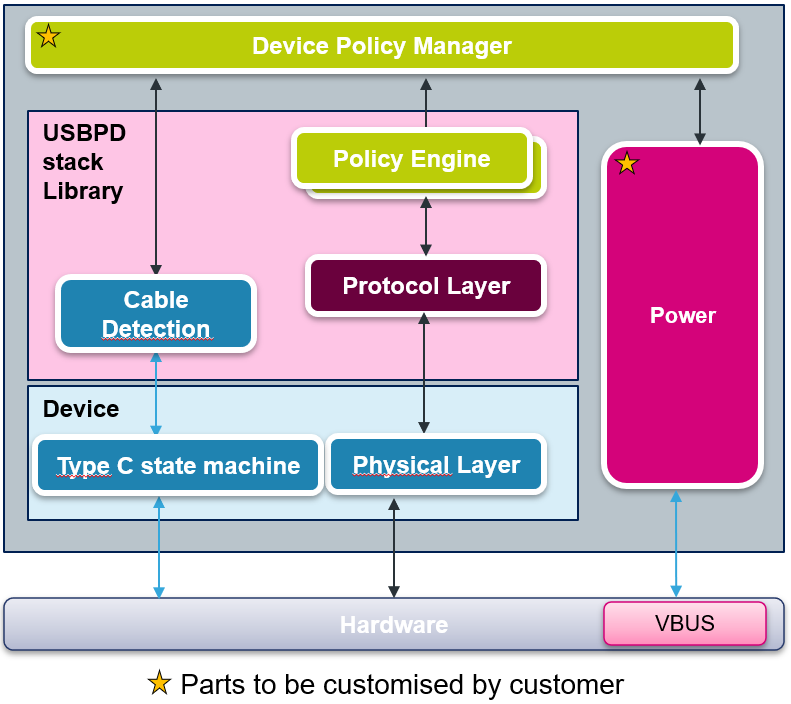
The Power delivery protocol is provided by ST as a library as below picture :
The library (pink box) only includes PE (Policy Engine), PRL (PRotocol Layer), and a part of CAD (CAble Detection). This library is common to all STM32 including the UCPD IP. The device part depends on the STM32 family (STM32G0, STM32G4...) The customer application is located in DPM (Device Policy Manager). This is where the strategy (choose the maximum power...) is coded.
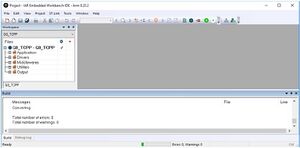
Here is an USBPD project example in IAR :
In this project, different folders can be found:
- The Application/User folder contains the source files that we need to edit to enrich the application. In particular the files *_user.c.
- The Drivers folder contains the HAL drivers for the STM32.
- The Middleware folder contains the source files and the libraries for FreeRTOS and USB-PD stack.
- The Utilities folder contains the GUI (UCPD monitor) and tracer embedded source files part.
- The Output folder contains the compilation result files.
STM32G0: Create a USB Power Delivery sink application in less than 10 minutes
4. STM32 compliant with USB Power Delivery
If you are looking for STM32 products that support Power Delivery, you can search in CubeMX for the integration of the UCPD IP. G0 is the only family with parts that contains up to 2 UCPD instances.
5. Specific tools
- STM32CubeMonitor for USB-C and Power Delivery is a tool to debug and configure the stack. DB3747
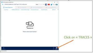
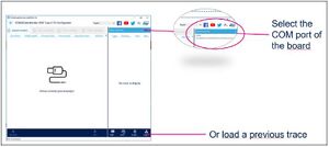
If the GUI responder is not activated in the embedded firmware, but the debug trace is available (UART through VCP of the STLink, and the compilation switch _TRACE activated) you may still see the trace in UCPD monitor by clicking on the Trace button in the bottom right corner.
The trace files are saved in c:\Users\your_login\AppData\Local\Temp\STM32CubeMonitor-UCPD\Acquisition\ with extension ".cpd"
6. STMicroelectronics Resources
- ST USB Type-C and Power delivery solutions page
- General application note describing how to do power delivery with the STM32. DB5225
- The USBPD stack User manual UM2552.
- A simple application note to guide on the creation of a Sink application with CubeMX. AN5418
7. Application Examples
You can find a lot of application examples in the G0 firmware package. For example in Projects\STM32G081B-EVAL\Demonstrations\DemoUCPD Or if you have downloaded the package through CubeMx : c:\Users\your_login\STM32Cube\Repository\STM32Cube_FW_G0_V1.3.0\
| MCU ref | Power role | Comment |
|---|---|---|
| STM32G071B-Disco | Sink | UM2546 |
| STM32G081B-Eval | Dual port DRP and Sink | UM2321 |
8. How to debug
- Add Debug trace inside embedded code :
by using the USBPD_TRACE_Add from file usbpd_trace.c, you can print information inside the gui tools
USBPD_TRACE_Add(6, 0, 0, 'string', 'string size');
example :
USBPD_TRACE_Add(6, 0, 0, "hello world", 11);
- Add livewatch on CAD_HW_Handles. This variable can be used to check the Type-C attachment or detachment.
See usbpd_cad_hw_if.c:
 #define USBPD_CAD_STATE_RESET 0u /*!< USBPD CAD State Reset */
 #define USBPD_CAD_STATE_DETACHED 1u /*!< USBPD CAD State No cable detected */
 #define USBPD_CAD_STATE_ATTACHED_WAIT 2u /*!< USBPD CAD State Port partner detected */
 #define USBPD_CAD_STATE_ATTACHED 3u /*!< USBPD CAD State Port partner attached */
- If the CC lines are empty, check that the TCPP is passed through, which means that the active LOW _DB pin is disabled at 3.3 V. This is due to the jumpers or some GPIO settings.
Note: In the current STM32CubeMX for STM32G4, there is an issue with the default GPIO mode for CC2. In usbpd_cad_hw_if.c there must be: LL_GPIO_SetPinMode(GPIOB, LL_GPIO_PIN_4, LL_GPIO_MODE_ANALOG); In STM32G4 versions before FW 1.2.0, the correct compilation switch is not set. An easy way is to correct this issue is to activate the compilation switch MB1367.
- For further debug, the VBUS measured value can be printed in the trace, using the user button.


