This message will disappear after all relevant tasks have been resolved.
Semantic MediaWiki
There are 1 incomplete or pending task to finish installation of Semantic MediaWiki. An administrator or user with sufficient rights can complete it. This should be done before adding new data to avoid inconsistencies.
Based on STM32 MC Motor Pilot 5.Y.2 V0.9.7 (included in STM32 MC-SDK 5.Y.2).
1. Overview of the STM32 MC motor-pilot tool
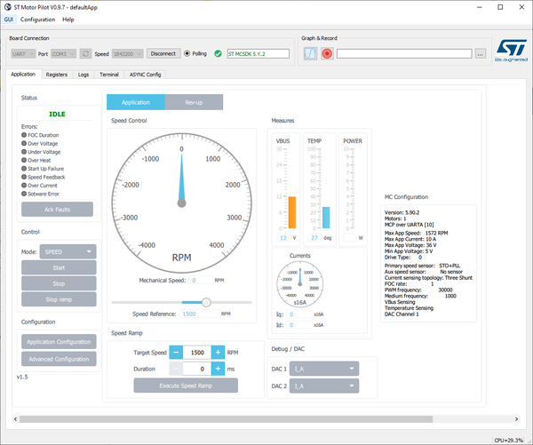
STM32 MC Motor Pilot is a monitoring tool for STM32 motor-control applications that:
- connects to MC applications built with the UI module through the serial port
- uses the same protocol as the current monitor
- allows for controlling, monitoring, and tuning MC applications
- replaces in the future the monitor part of STM32 MC workbench
- current available version is an already usable preview

STM32 MC Motor Pilot added values are:
- enhanced plotting feature: the user can now plot most registers
- the user can easily customize GUI at run time
- to fit specific needs or to experiment with new firmware features
- solid foundation to support future firmware features
- ACIM, 6-Step, sensor-less zero speed, enhanced debug features
- runs on all three MCD target platforms: Windows, Mac, and Linux
2. STM32 MC motor-pilot quick guide
2.1. Installation and run
STM32 MC Motor Pilot is now automatically installed with STM32 MC SDK.
A shortcut is now created in Windows menus to run it.
2.2. Quick start-up
2.2.1. Quick step 1
- MotorPilot:
- starts unconnected

- lists available serial ports

- displays the default UI
- starts unconnected
- Connect a Motor Pilot board to the PC.
- Click on Connect.

2.2.2. Quick step 2
- When MotorPilot is connected, it:
- displays version of embedded firmware

- retrieves importants parameters for motor control form the board and adjust the GUI with theses informations
- starts to monitor parameters needed by the GUI
- displays version of embedded firmware
- Spin the motor:
- Click on the Start button.

- Click on the Start button.
- Motors starts and the pilot updates the GUI.


2.2.3. Quick step 3
- Control the motor:
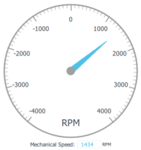
- Slide the knob to set the speed

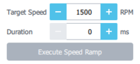
- Set Target Speed, Duration and click to apply a ramp
- Slide the knob to set the speed


- Click Stop Ramp to stop it before end

- Click Stop to stop spinning the motor


3. MC application parameters
STM32 MC Motor Pilot gets MC application parameters from the board and adapts widgets to them.
4. MC application advanced settings
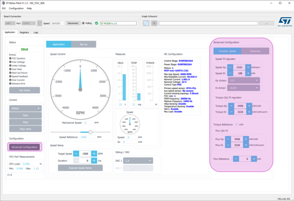
4.1. Speed PID, Toque PID, Flux PID and Flux reference
- Click Advanced Configuration:
- displays additional panel with more settings
- displays additional panel with more settings
- As in the current monitor, customizes:
- Speed PID
- Toque PID
- Flux PID
- Set Flux reference

4.2. State Observer, PLL parameters, CORDIC parameters and DAC settings
- Click Advanced Configuration
- Displays additional panel with more settings
- As in the current monitor, customizes:
- State Observer + PLL parameters
- State Observer + CORDIC parameters

- if DAC is available on your board you can select which register you want to output on it
4.3. Handling errors
4.3.1. Control Board disconnection
Board freeze due to firmware critical error or breakpoint trigger:
- Resume execution or reset the board, and the connection resumes.

4.3.2. Firmware errors
- As with the current monitor, current and past errors are indicated.
- Clicking the Ack Faults button has no effect in the FAULT_NOW state

- Wait for the fault conditions to vanish to enter the FAULT_OVER state

- Then click on Ack Faults to go back to IDLE

4.4. Viewing and plotting registers with low-speed plotting
With this method of plot, any register can be plot but at low rate (polling every 200 ms by default)
- Clicking the Registers tab displays the list of all registers (see (1) on the following figure)
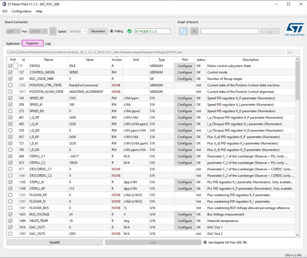
- Click a "Click to Plot" button (see (2) on the figure)
- Opens a plot window the first time
- Lets the user decide where to plot the other times (see (3) on the figure)
- Lets the user choose to stop showing the already pointed register (see (4) on the figure).


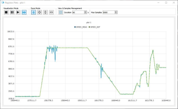
4.5. Viewing and plotting registers with high-speed plotting
With this method of plot, only a subset of registers can be plot at PWM frequency rate
- Once the motor is connected (and motor started)
- Click on the "Plot" button

- A "High Frequency Plot" window opens:

- Click again to open more plot windows
- Resize these windows to optimize the display of plots on your desktop
- Right-click to select the register you want to plot:

- Click again to plot more registers:

- The data display width is defined by adjusting the buffer size (change buffering to display more data):

- When displaying 2 registers, you can switch to the X / Y plot:

- Dynamic plot display can be paused and resumed as desired.
- Each register plot can be hidden or displayed by double-clicking on the register name in the plot legend (then when the register plot is hidden, the corresponding register name is strikethrough).

4.6. Rev-up configuration
- Click on "Rev-up" button and then the application panel is replaced by rev-up configuration panel.

- This panel allows to set up to 5 rev-up steps by direct edit in the corresponding table for which a step rev-up duration, a final torque value and a final speed value are defined. (use the same values to have less steps).
4.7. UI is changeable at run-time
- Click on menu item File => Load
- Search for a .qml file and open it.
- For instance, GUI\PositionControlApp.qml found in the release.
- This loads a new GUI with other features
- In the case of PositionControlApp.qml, a position control enabled monitoring application.

- Users are able to change the UI by copying an existing ".qml" file and editing it.