1. Peer to Peer Profile
The Peer to Peer Profile is a Generic Attribute Profile (GATT) based low-energy profile defined by STMicroelectronics with proprietary UUIDs(128 bits)
The Peer to Peer Profile, widely used for direct connection, defines the communication between a GATT-server of a Peer to Peer Server device, and a GATT-client Collector device, such as a smartphone, STM32WBA Peer to Peer Client or Peer to Peer Router devices.
- The Peer to Peer Server:
- Contains the P2P Service, which expose two characteristics (Notification & Write) in order to create a bi-direction data communication.
- Is the GATT server.
- The Collector:
- Accesses the information exposed by Peer to Peer Server, controls it with the Write characteristics, receives Notification from it.
- Is the GATT client.
This wiki page is the description of the Peer to Peer Server and Peer to Peer Client projects provided within the STM32CubeWBA MCU Package[1]
Follow this "link" for Peer to Peer Router project explanation.
| Bluetooth® LE Peer to Peer Profile & STM32WBA |
|---|
1.1. STM32WBA Peer to Peer Server application
The table below describes the structure of Peer to Peer service:
| Bluetooth® LE Peer to Peer Service specification | ||||||||||||||||||||
|---|---|---|---|---|---|---|---|---|---|---|---|---|---|---|---|---|---|---|---|---|
|
Peer To Peer Server is exported as a Service
- LED characteristic:
- Used to control LED1 (Blue) on STM32WBA platform by remote device .
| Peer to Peer Service - LED Characteristic | |||||||||
|---|---|---|---|---|---|---|---|---|---|
|
- SWITCH Characteristic:
- Used to switch LED or Lamp on Collector device.
| Peer to Peer Service - SWITCH Characteristic | |||||||||
|---|---|---|---|---|---|---|---|---|---|
|
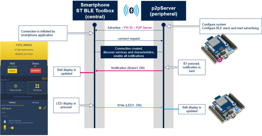
| Example of flow diagram between STM32WBA & ST BLE Toolbox |
|---|
At start up, Peer To Peer Server application starts Advertising including the Manufacturer Advertising Elements as described below:
| 0 | 1 | 2-3 | 4 | 5 | 6 | 7 | 8 | 9 | 10-15 | |
|---|---|---|---|---|---|---|---|---|---|---|
| Length | Manufacturer ID | Company | BlueSTSDK Version | Device ID | Firmware ID | Option 1 | Option 2 | Option 3 | Device Address | |
| P2P Server | 0x0F | 0xFF | 0x0030 STMicro | 0x02 | 0x8B Nucleo-WBA | 0x83 | 0x00 | 0x00 | 0x00 | 0x08E12Axxxx |
Advertising is stopped after 30s, pressing B1 restart it.
1.2. STM32WBA Peer to Peer Client application
It acts as a Central device with the support of GATT Client Layer.
At start up, by pressing B1 button, Peer To Peer Client application:
- Starts scanning to detect Peer To Peer Sever application by filtering the Firmware ID of the STMicroelectronics Manufacturer advertising data
- Stops Scanning once P2P server detected
- Connects to the P2P Server to establish the connection.
- Discovers GATT Service & Characteristics of the P2P server
- Enable all GATT server notification characteristics
Once connected, the Peer To Peer Client application:
- by pressing B1 button, write a message to toggle the Blue LED of the P2P Server
- Receive notification to toggle the on board Blue LED from remote P2P Server Application.
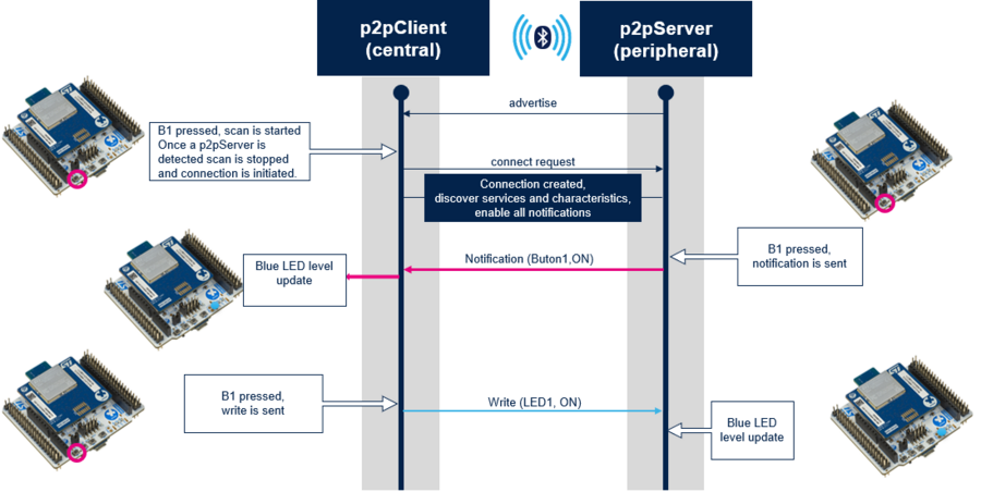
| Example of flow diagram between STM32WBA P2P Server & P2P Client |
|---|
1.3. On board buttons configuration
| P2P Applications Nucleo-WBA buttons configuration | ||||||||||||||||||||||||
|---|---|---|---|---|---|---|---|---|---|---|---|---|---|---|---|---|---|---|---|---|---|---|---|---|
|
2. Requirements
2.1. Software and system requirements
The software required are the following (minimum IDEs version):
- IAR Embedded Workbench for ARM (EWARM) toolchain V??
- RealView Microcontroller Development Kit (MDK-ARM) toolchain V??
- STM32CubeIDE toolchain V?? [2].
Programmer:
- STM32CubeProgrammer[3] : To flash the board with an already generated binary
2.2. Hardware requirements
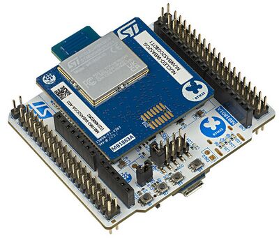
NUCLEO-WBA5 [4] is necessary to install the application.
| Hardware platform illustration |
|---|
|
|
2.3. Collector applications compatible
The STM32CubeWBA Health Thermometer Sensor project is compatible with the following collector:
3. STM32WBA P2P Server & P2P Client examples description
3.1. Project directory
The "BLE_p2pserver" & "BLE_p2pclient"applications are available by downloading STM32CubeWBA MCU Package[5]. LINK TO UPDATE
| P2P Server & Client projects directory |
|---|
3.2. Project description
3.2.1. Structure
Software project structure with the most important parts:
| P2P Server / Client project structure | |
|---|---|
|
WARNING: Do not modify the files in Middlewares folder |
3.2.2. Application initialization
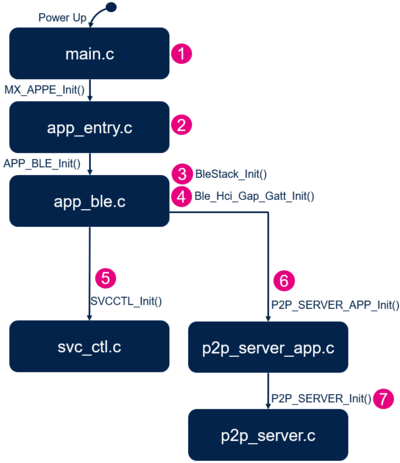
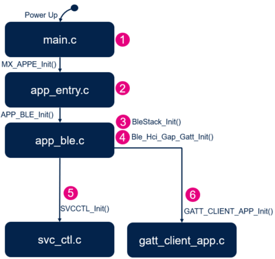
The different steps of the application initialization are described below:
| P2P Server project initialization |
|---|
| P2P Client project initialization |
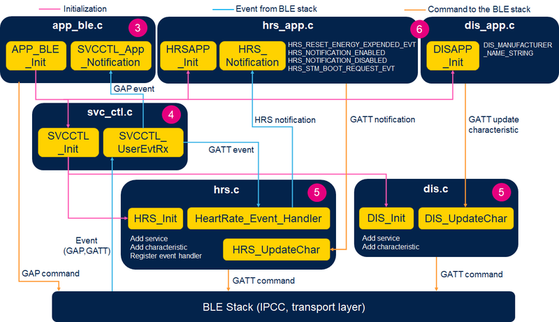
3.2.3. GAP and GATT initialization and interaction
The Bluetooth LE Heart Rate Sensor application initialization is done within app_ble.c
- Start the BLE stack - initialize the device as peripheral - configure and start advertising: ADV parameters, local name, UUID - APP_BLE_init()
- Call the services controller initialization SVCCTL_Init() - svc_ctl.c
- Manage the GAP event - SVCCTL_App_Notification()
- EVT_LE_CONN_COMPLETE - provides information of the connection interval, slave latency, supervision timeout
- EVT_LE_CONN_UPDATE_COMPLETE - provides the new information of the connection
- EVT_DISCONN_COMPLETE - informs the application about the link disconnection and the reason
- EVT_ENCRYPT_CHANGE - informs the application weather the link is encrypted
The Services management is done by the service controller - svc_ctl.c
- Call the Initialization function of all the developed services - SVCCTL_SvcInit()
- Heart Rate Service - HRS_Init() - hrs.c
- Device Information service - DIS_Init() - dis.c
- Register Services Event Handler - SVCCTL_RegisterSvcHandler(...)
- Manage events - SVCCTL_UserEvtRx ()- from the BLE Host Stack and redirect them to the services registered - HearRate_Event_Handler() - or gap event handler - SVCCTL_App_Notification
The Heart Rate Service hrs.c manages the specification of the service:
- Service Init - HRS_Init()
- Register Heart Rate Event Handle to Service Controller - SVCCTL_RegisterSvcHandler(HearRate_Event_Handler);
- Initialize Service UUID – add Heart Rate service as Primary services
- Initialize Heart rate measurement characteristic
- Initialize Body Sensor location characteristic
- Update Heart Rate measurement characteristic - HRS_UpdateChar()
- Update Body Sensor location characteristic Value - HRS_UpdateChar()
- Manage the GATT event from BLE Stack - HeartRate_Event_Handler()
- ACI_GATT_WRITE_PERMIT_REQ_VSEVT_CODE
- Reception of a Write Command: HR Control Point Characterictic Value
- Send an aci_gatt_write_response() with an OK or KO status.
- Notify the application to Reset Energy Expended - HRS_Notification(HRS_RESET_ENERGY_EXPENDED_EVT)
- Reception of a Write Command: HR Control Point Characterictic Value
- ACI_GATT_ATTRIBUTE_MODIFIED_VSEVT_CODE
- Reception of an attribute modification - HR Measurement Characteristics Description Value : ENABLE or DISABLE Notification
- Notify application of the Measurement Notification - HRS_Notification(HRS_NOTIFICATION_ENABLED/DISABLED)
- Reception of an attribute modification - HR Measurement Characteristics Description Value : ENABLE or DISABLE Notification
- ACI_GATT_WRITE_PERMIT_REQ_VSEVT_CODE
| Heart Rate Sensor software module interaction |
|---|
The application level of the Heart Rate Sensor is done with hrs_app.c:
- Initialization of the context of the application
- Measurement value flags support
- Body sensor location - HRS_BODY_SENSOR_LOCATION_HAND
- Receive notification from the Heart Rate Service - HRS_Notification()
- When Heart rate measurement characteristics are enabled by the remote, simulate every 1 s the Heart Rate Measure (HRSAPP_Measurement) and increase the energy expended to transfer to the remote device (collector) - HRS_UpdateChar()
3.3. Build and install
Follow the steps described in Bluetooth® LE Build and Install Application page, applying them for STM32WBA BLE_HealthThermometer project.
3.4. How to use
Once the BLE Heart Rate application is installed on the STM32WB platform, launch ST BLE Sensor or ST BLE ToolBox smartphone application. Then, scan and connect the device called HRSTM to the application.
Once the Bluetooth® LE connection is established and the notification enabled by the smartphone:
- Heart Rate measurement is provided to remote every 1 s.
- thanks to the timer server and the task manager
BLE Heart Rate application support the pairing procedure
- SW1 allows to clear the security database
- SW2 allows to request pairing
With the WB55.Nucleo board, it is possible to change RF PHY modulation
- SW3 allows to switch to 2 Mbits or 1 Mbits PHY
3.5. UART debug trace
Thanks to the debug log via UART interface, it is possible to trace the application project.
To enable the traces within the project, enable them within app_ble.c as described below:
/**
 * When set to 1, the traces are enabled in the BLE services
 */
#define CFG_DEBUG_BLE_TRACE     1
/**
 * Enable or Disable traces in application
 */
#define CFG_DEBUG_APP_TRACE     1
| Heart Rate Sensor - Initialization phase | Connected Phase |
|---|---|
Wireless Firmware version 1.13.0
Wireless Firmware build 5
FUS version 1.2.0
>>== SHCI_SUB_EVT_CODE_READY

>>== WIRELESS_FW_RUNNING
>>== DBGMCU_GetRevisionID= 2001

==>> Start Ble_Hci_Gap_Gatt_Init function
  Success: hci_reset command
  Success: aci_hal_write_config_data command - CONFIG_DATA_PUBADDR_OFFSET
  Public Bluetooth Address: 00:80:e1:26:ff:eb
  Success: aci_hal_write_config_data command - CONFIG_DATA_IR_OFFSET
  Success: aci_hal_write_config_data command - CONFIG_DATA_ER_OFFSET
  Success: aci_hal_set_tx_power_level command
  Success: aci_gatt_init command
  Success: aci_gap_init command
  Success: hci_le_set_default_phy command
  Success: aci_gap_set_io_capability command
  Success: aci_gap_set_authentication_requirement command
  Success: aci_gap_configure_whitelist command
==>> End Ble_Hci_Gap_Gatt_Init function

Device Information Service (DIS) is added Successfully 000C
Manufacturer Name Characteristic Added Successfully  000D
Model Number String Characteristic Added Successfully  000F
Heart Rate Service (HRS) is added Successfully 0011
Heart Rate Measurement Characteristic Added Successfully  0012
Sensor Location Characteristic Added Successfully  0015
Control Point Characteristic Added Successfully  0017
==>> aci_gap_set_discoverable - Success
==>> Success: Start Fast Advertising
|
>>== HCI_LE_CONNECTION_COMPLETE_SUBEVT_CODE - Connection handle: 0x801
     - Connection established with Central: @:72:16:9d:9e:d5:8e
     - Connection Interval:   48.75 ms
     - Connection latency:    0
     - Supervision Timeout: 5000 ms

>>== HCI_LE_CONNECTION_UPDATE_COMPLETE_SUBEVT_CODE
     - Connection Interval:   7.50 ms
     - Connection latency:    0
     - Supervision Timeout: 5000 ms

>>== HCI_LE_CONNECTION_UPDATE_COMPLETE_SUBEVT_CODE
     - Connection Interval:   48.75 ms
     - Connection latency:    0
     - Supervision Timeout: 5000 ms

ACI_GATT_ATTRIBUTE_MODIFIED_VSEVT_CODE HRS_NOTIFICATION_ENABLED
==>> hci_le_read_phy - Success
==>> PHY Param  TX= 1, RX= 1
==>> hci_le_set_phy PHY Param  TX= 2, RX= 2 - Success

==>> HCI_LE_PHY_UPDATE_COMPLETE_SUBEVT_CODE - status ok
==>> hci_le_read_phy - Success
==>> PHY Param  TX= 2, RX= 2
|
4. References
