Click here for Bluetooth® LE overview
1. STM32WBA boards
1.1. NUCLEO-WBA55CG board
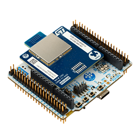
NUCLEO-WBA55CG[1] is a Bluetooth® Low Energy wireless and ultra-low-power board embedding a powerful and ultra-low-power radio compliant with the Bluetooth® Low Energy SIG specification v5.4, IEEE 802.15.4-2015 PHY and MAC, supporting Thread®, Matter®, and Zigbee®.
- Called the Ultra-low-power wireless STM32WBA55CG[2] microcontroller based on the Arm® Cortex®‑M33 core, featuring 1 Mbyte of flash memory and 128 Kbytes of SRAM in a UFQFPN48 package
The NUCLEO-WBA55CG is composed of:
- MCU RF board (MB1803):
- 2.4 GHz RF transceiver supporting Bluetooth® specification v5.4
- IEEE 802.15.4-2015 PHY and MAC, supporting Thread®, Matter®, and Zigbee®
- Arm® Cortex® M33 CPU with TrustZone®, MPU, DSP, and FPU
- Integrated PCB antenna
- Mezzanine Board (MB1801)
- Three user LEDs
- Three user and one reset push button
- Board connectors:
- USB Type-C®
- ARDUINO® Uno V3 expansion connector
- ST morpho headers for full access to all STM32 I/Os
- Flexible power-supply options: ST-LINK USB VBUS or external sources
- On-board STLINK-V3 debugger/programmer with USB re-enumeration capability: mass storage, virtual COM port, and debug port
- Comprehensive free software libraries and examples available with the STM32CubeWBA MCU Package[3]
- Support of a wide choice of Integrated Development Environments (IDEs) including IAR Embedded Workbench®, MDK-ARM, and STM32CubeIDE
| NUCLEO-WBA55CG |
|---|
1.2. STM32WBA55G-DK1 board
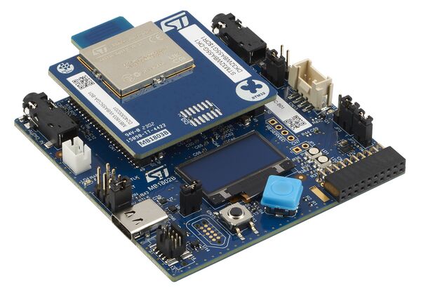
The STM32WBA55G-DK1 Discovery kit [4] is a complete demonstration and development platform for the STM32WBA55CG [2] microcontroller, featuring an Arm® Cortex®‑M33 core with Arm® TrustZone® and mainline security extension, 1 Mbyte of flash memory, and 128 Kbytes of SRAM in a UFQFPN48 package, as well as smart peripheral resources.
The STM32WBA55G-DK1 is composed of:
- MCU RF board (MB1803):
- 2.4 GHz RF transceiver supporting Bluetooth® specification v5.4
- Bluetooth® Low Energy specification supporting LE Audio
- Arm® Cortex® M33 CPU with TrustZone®, MPU, DSP, and FPU
- Integrated PCB antenna
- Mezzanine Board (MB1802)
- One digital microphone
- OLED display
- One user LED
- User joystick with 4-direction control and selector button
- One reset push button
- Board connectors:
- USB Type-C®
- One jack socket with stereo line input and one jack socket with stereo output and microphone input
- Battery
- Grove
- MIPI10
- Tag‑Connect™ 10‑pin footprint
- ARDUINO® Uno V3 expansion connector
- STMod+ expansion connector
- Flexible power-supply options: ST-LINK USB VBUS or external sources
- On-board STLINK-V3 debugger/programmer with USB re-enumeration capability: mass storage, virtual COM port, and debug port
- Comprehensive free software libraries and examples available with the STM32CubeWBA MCU Package[3]
- Support of a wide choice of Integrated Development Environments (IDEs) including IAR Embedded Workbench®, MDK-ARM, and STM32CubeIDE
| STM32WBA55G-DK1 |
|---|
2. Hardware platform configuration
2.1. Debug log via UART interface
The NUCLEO-WBA55CG [1] embeds the ST-LINK/V3 in-circuit debugger and programmer for STM32 microcontrollers.
STM32WBA microcontroller supports the STM32 virtual COM port driver for communication with a PC using a serial interface.
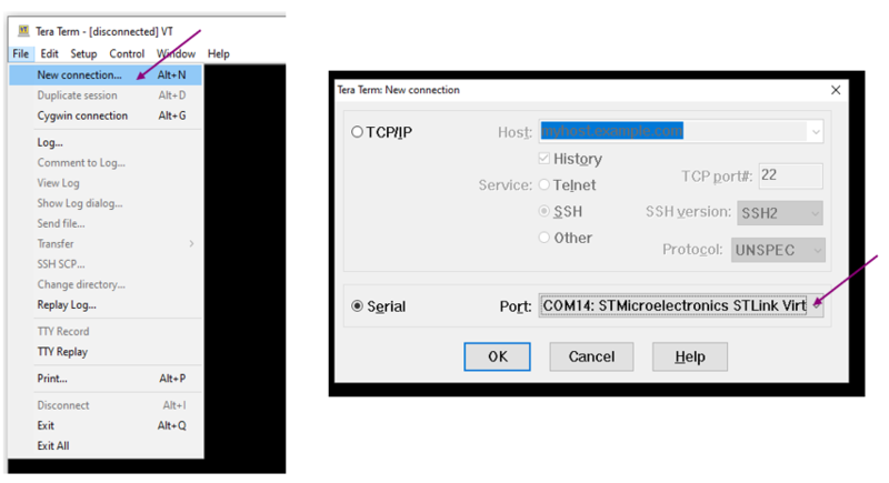
Use any convenient software terminal to open the serial communication port of the PC to check the messages from the board. Select the serial port and set up the connection as follows (example done with Tera Term software).
Set a new serial connection to the ST platform:
| Tera Term setup (1/2) |
|---|
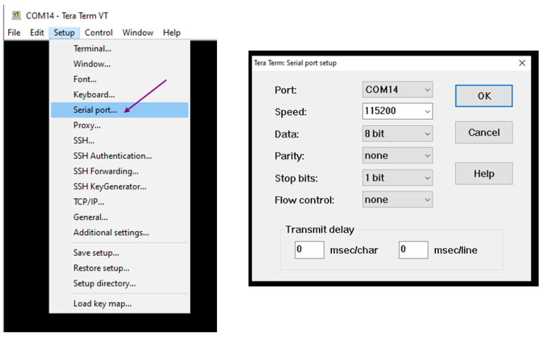
Setup the serial connection as below:
| Tera Term setup (2/2) |
|---|
2.2. How to connect external debuggers
This paragraph explains how to connect an external debugger to the NUCLEO-WBA55CG[1] platform. This could be either an ST-LINK or a J-LINK debugger.
To disconnect the embedded ST-LINK, set SW1 to position 3.
2.2.1. Setup using ST-LINK
- On the miniboard, check if CN3 is fitted with an STDC14 connector. Add one if not.
- Place 47 Ohm resistors (type 0402) for R2-R9 (i.e. 8 components).
- Remove jumpers JP1 and JP2
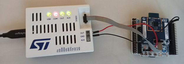
- Connect the ST-LINK output OUT to connector JP2.2
- Connect ST-LINK GND to CN13.1
- Connect a ribbon between ST-LINK DEBUG and CN3.
| ST-link debugger connected to a NUCLEO-WBA55CG[1] board |
|---|
2.2.2. Setup using J-LINK
- On the miniboard, check if CN3 is fitted with an STDC14 connector. Add one if not.
- Place 47 Ohm resistors (type 0402) for R2-R9 (i.e. 8 components).
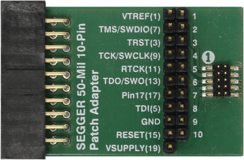
- Plug the JLINK 10-pin patch adapter into the J-LINK
- Connect a ribbon between this adapter and JP1 on the WBA5x miniboard
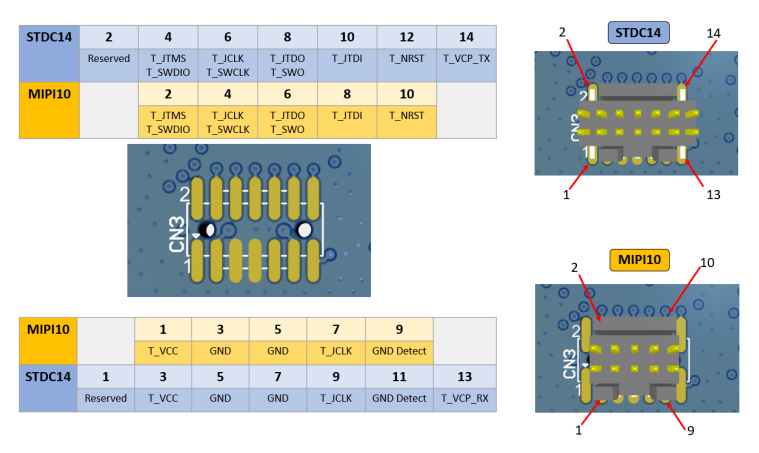
| Correspondence of pins from CN3 footprint to STDC14 or MIPI10 connector |
|---|
| J-Link debugger connected to NUCLEO-WBA55CG[1] board |
|---|
| The Segger patch adapter needs to be inserted between the J-Link and the NUCLEO-WBA55CG[1] |
|---|
3. Going further
- Build and load the flash memory of an existing example : Build Bluetooth® LE Project article
4. References
