| Delivery for this function pack is being prepared |
Sensing and condition monitoring are two of the major component of the IoT and predictive maintenance systems, allowing context awareness, production performance improvement, maintenance cost reduction and a drastic decrease of the downtime due to routine maintenance.
The FP-AI-MONITOR1 function pack helps to jump-start the implementation and development of classification and condition monitoring applications designed with X-CUBE-AI Expansion package for STM32Cube and with the NanoEdge™ AI Studio solution.
FP-AI-MONITOR1 supports on device learning for the anomaly detection using NanoEdge AI libraries and on device inference for both classification problems based on classical machine learning and Neural networks as well as for the anomaly detection using NanoEdge AI studio. The evaluation board supported is a sensor node STEVAL-STWINKT1B with STM32L4R9ZI ultra-low power microcontroller. It covers the entire design of the Machine Learning cycle from the data set acquisition to the integration on a physical node.
FP-AI-MONITOR1 implements a wired interactive CLI to configure the node, and manage the learn and detect phases. In addition to this for simple operation in the field, a standalone battery-operated mode is also supported, which allows basic controls through the user button, without using the console.
This article provides an overview of the following topics:
- The required hardware and software,
- Setting up the hardware and software components,
- Performing the vibration sensor data collection using a prebuilt binary of FP-SNS-DATALOG1,
- Running a One-class SVM model for anomaly detection on the device
- Building the model using Scikit-learn,
- Exporting as onnx model using onnx-runtime,
- Generating C code using X-Cube-AI, and
- Running on STEVAL-STWINKT1B .
- Generating, Installing, and testing the NanoEdge™ AI machine learning libraries on the STEVAL-STWINKT1B using the provided function pack, and
- Some links to useful online resources, to help a user to better understand and customize the project for his own needs.
For full user instructions of the FP-AI-MONITOR1 please refer to this article.
1. Hardware and software overview
1.1. SensorTile Wireless Industrial Node Evaluation Kit STEVAL-STWINKT1B
The STWIN SensorTile wireless industrial node (STEVAL-STWINKT1B) is a development kit and reference design that simplifies the prototyping and testing of advanced industrial IoT applications such as condition monitoring and predictive maintenance. It is powered with Ultra-low-power Arm® Cortex®-M4 MCU at 120 MHz with FPU, 2048 kbytes Flash memory (STM32L4R9). STWIN SensorTile is equipped with a microSD™ card slot for standalone data logging applications. STWIN SensorTile is equipped with a wide range of industrial IoT sensors including:
- an ultra-wide bandwidth (up to 6 kHz), low-noise, 3-axis digital vibration sensor (IIS3DWB)
- a 6-axis digital accelerometer and gyroscope iNEMO inertial measurement unit (IMU) with machine learning (ISM330DHCX)
and much more. Please refer to this link for all the sensors and features supported by STWIN. Other attractive features include:
- a Li-Po battery 480 mAh to enable standalone working mode
- STLINK-V3MINI debugger with programming cable to flash the board
- a Plastic box for ease of placing and planting the SensorTile on the machines for condition monitoring. For further details, the users are advised to visit this link
1.2. FP-AI-MONITOR1 Software Description
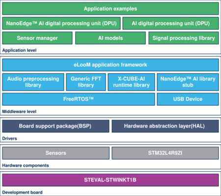
The top-level architecture of the FP-AI-MONITOR1 function pack is shown in the following figure.
2. Prerequisites and setup
2.1. HW prerequisites and setup
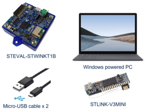
To use the FP-AI-NANOEDG1 function pack on STEVAL-STWINKT1B, the following hardware items are required:
- STEVAL-STWINKT1B development kit board,
- Windows® powered laptop/PC (Windows® 7, 8, or 10),
- Two MicroUSB cables, one to connect the sensor-board to the PC, and another one for the STLINK-V3MINI, and
- an STLINK-V3MINI.
2.2. Software requirements
2.2.1. FP-AI-MONITOR1
- Download the FP-AI-MONITOR1, package from ST website, extract and copy the .zip file contents into a folder on your PC. The package contains binaries and source code, for the sensor-board STEVAL-STWINKT1B.
2.2.2. IDE
- One of the following IDEs must be installed:
- STMicroelectronics - STM32CubeIDE version 1.5.0
- IAR Embedded Workbench for Arm (EWARM) toolchain V8.50.5 or later
- RealView Microcontroller Development Kit (MDK-ARM) toolchain V5.31
2.2.3. STM32 ST-LINK Utility
- A software interface for programming STM32 microcontrollers. This software is only required to install the prepared binaries provided in the function pack folder at the start. Note that this software will be used by not just users to install the already provided binaries but by STM32CubeIDE also to program the boards with the generated binaries.
- This software can be downloaded from STSW-LINK004.
2.2.4. Tera Term
- Tera Term is an open-source and freely available software terminal emulator, which is used to host the CLI of the FP-AI-MONITOR1 through a serial connection.
- Users can download and install the latest version available from Tera Term.
2.2.5. STM32CubeMX
STM32CubeMX is a graphical tool that allows a very easy configuration of STM32 microcontrollers and microprocessors, as well as the generation of the corresponding initialization C code for the Arm® Cortex®-M core or a partial Linux® Device Tree for Arm® Cortex®-A core), through a step-by-step process. Its salient features include:
- Intuitive STM32 microcontroller and microprocessor selection.
- Generation of initialization C code project, compliant with IAR™, Keil® and STM32CubeIDE (GCC compilers) for Arm®Cortex®-M core
- Development of enhanced STM32Cube Expansion Packages thanks to STM32PackCreator, and
- Integration of STM32Cube Expansion packages into the project.
For downloading and details of all the features please visit st.com.
2.2.6. X-Cube-AI
X-CUBE-AI is an STM32Cube Expansion Package part of the STM32Cube.AI ecosystem and extending STM32CubeMX capabilities with automatic conversion of pre-trained Artificial Intelligence models and integration of generated optimized library into the user's project. The easiest way to use it is to download it inside the STM32CubeMX tool (version 7.0.0 or newer) as described in user manual Getting started with X-CUBE-AI Expansion Package for Artificial Intelligence (AI) (UM2526). The X-CUBE-AI Expansion Package offers also several means to validate the AI Models (both Neural Network and Scikit-Learn models) both on desktop PC and STM32, as well as measure performance on STM32 devices (Computational and memory footprints) without user handmade ad-hoc C code.
2.2.7. Python 3.7.X
Python is an interpreted high-level general-purpose programming language. Python's design philosophy emphasizes code readability with its notable use of significant indentation. Its a language constructs as well as its object-oriented approach aim to help programmers write clear, logical code for small and large-scale projects. To build and export the Onnx models the reader requires to setup a Python environment with a list of packages. The list of the required packages along with their versions can be found as a text file in the package at location /FP-AI-MONITOR1/Utilities/AI_resources/requirements.txt.
2.2.8. NanoEdge AI Studio
The function pack lets user to use the AI libraries generated by NanoEdgeTM AI Studio powered by Cartesiam. The user needs to generate the libraries from the NanoEdge AI Studio and then embed these libraries in the FP-AI-MONITOR1. The Studio can be downloaded from this Cartesiam.ai as a free trial version for the STMicroelectronics boards.
2.3. Installling the Function Pack to STWIN
2.3.1. Get the function pack
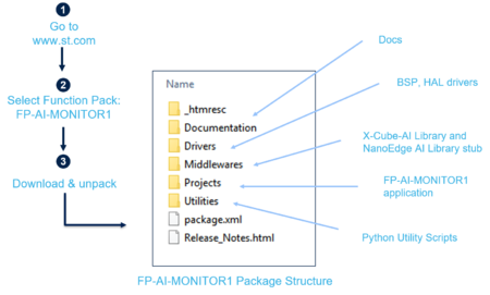
The first step is to get the function pack. The FP-AI-MONITOR1 can be downloaded from ST website. Once the pack is downloaded, the user can unpack/unzip it and copy the contents to a folder on the PC. The steps of the process along with the contents of the folder are shown in the following image.
2.3.2. Flashing the application on the sensor board STEVAL-STWINKT1B
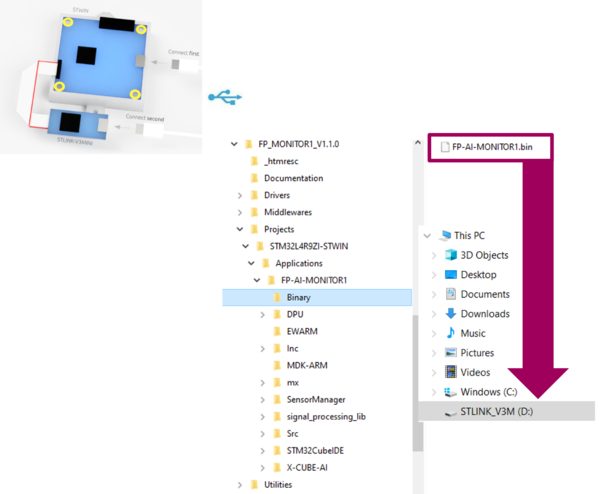
Once the package has been downloaded and unpacked, the next step is to program the sensor node with the binary of the function pack. For the convenience of the users, the function pack is equipped with a pre-built binary file of the project. This binary file can be found at path /FP-AI-MONITOR1/Projects/Binary/FP-AI-MONITOR1.bin. The sensor board can be very easily programmed with the provided binary by simply performing a drag-and-drop action as shown in the figure below.
3. FP-AI-MONITOR1 console application
FP-AI-MONITOR1 provides an interactive command-line interface (CLI) application. This CLI application equips a user with the ability to configure and control the sensor node, to perform learning (for NanoEdge TM AI libraires), and (anomaly) detection operations on the edge. The following sections provides a small guide on how a user can install this CLI application on a sensor board and control it through the CLI from Tera Term.
3.1. Setting up the Console
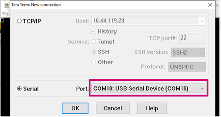
Once the sensor board is programmed with the binary of the project (as shown in section 2), the next step is to set up the serial connection of the board with the PC through the Tera Term. To do so, start Tera Term, and create a new connection by either selecting from the toolbar, select the proper port to establish the serial communication with the board. In the figure below, this is COM10 - USB Serial Device (COM 10).
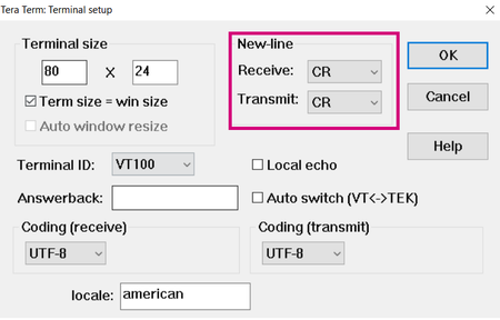
Set the following parameters:
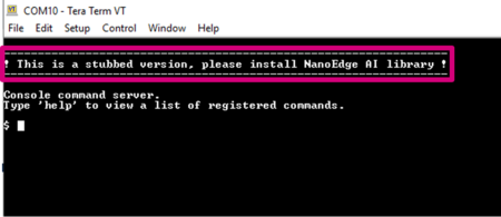
Once the connection is made the user will see a message like below. If this message does not appear, the user can try to reset the board, to make this message appear.
Typing help will show the list of all available commands.
3.2. Configure the sensor for data logging
Through the CLI interface, a user can configure the supported sensors on the sensor-board and can log the data with these sensors. In the ISM330DHCX sensor, there are multiple sub-sensors to log acceleration and gyrometer data. These sub-sensors can be individually configured. The configurable options for these sensors and sub sensors include:
- Activate/deactivate the sensor or a sub-sensor,
- Set an output data rate (ODR) from the list of available options,
- Set full-scale range from the list of available options.
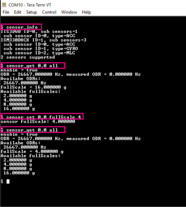
The list of all the supported sensors and sub-sensors can be displayed on the CLI console by entering the command:
$ sensor_info
This command will print the ids for the supported sensors with sub-sensors. The detailed information of a given supported sensor or sub-sensor can be shown by typing command:
$ sensor_get <sensor_id.sub-sensor_id> all
Similarly, the values for any of the available configurable parameters can be set through command
$ sensor_set <sensor_id.sub-sensor_id> <param> <val>
3.3. Data collection
Data collection is out of the scope of this function pack. However, to facilitate the users a .bin file for FP-SNS-DATALOG1 along with a CLI example to log the data using all the sensors on the STEVAL-STWINKT1B is provided in the function pack at /FP-AI-MONITOR1/Utilities/HSDatalog/. The cli_example folder contains a .bat file which can be used to do the datalogging directly on the computer in the cli_example folder.
For details on how to use it the users are invited to refer to the page 4 of the article.
4. Classification applications for sensing
4.1. Data Preperation
4.2. SVM Parameter Search
4.3. Exporting the Model to .onnx
4.4. Creating the C Code using X-Cube-AI
4.5. Embedding the CubeAI Model into the FP-AI-MONITOR1
4.6. Running the detection on STEVAL-STWINKIT1B
5. Condition monitoring using NanoEdge AI Machine Learning library
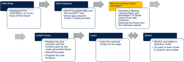
This section provides a complete method to set up an application for condition monitoring using FP-AI-NANOEDG1. The steps are provided with brief details in the diagram below.
The details on how to set up the sensor board with a function pack as well as data collection have been already provided in the sections above. The following sections provide the details on library generation, installation, training, and testing.
5.1. Generating a condition monitoring library
The AI libraries for the condition monitoring for this function pack are generated and provided by NanoEdge AI Studio, a solution provided by Cartesiam. This section provides a step-by-step guide on how to generate these condition monitoring libraries, installing them on the sensor node by linking them to the provided project in FP-AI-NANOEDG1 and then using them to perform the condition monitoring on the edge, by running first in training and then detection mode.
5.1.1. Data logging for normal and abnormal conditions
The library generation requires some sample data to be provided to the NanoEdge AI Studio. This data will provide the context of the set up to be monitored. The first step is to log the data for the normal and abnormal conditions using the data logging application provided in this function pack.
5.1.2. Data preparation for library generation with NanoEdge AI Studio
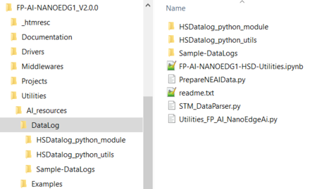
The data logged through the datalogger is in the binary format and is not user readable in its current condition. To convert this data to a useful form, FP-AI-NANOEDG1 provides Python™ utility scripts on the path /FP-AI-NANOEDG1_V2.0.0/Utilities/AI-resources/DataLog/ as shown in the figure below.
The following calls to the python functions will convert the datalogs in STM32_DL_001, and STM32_DL_002 data directories to human-readable .csv files.
>> python STM_DataParser.py ./Sample-DataLogs/STM32_DL_001
>> python STM_DataParser.py ./Sample-DataLogs/STM32_DL_002
Once the .csv files are generated for every data log, then the user needs to prepare the NanoEdge TM AI Studio compliant files. This can be achieved by issuing following python call.
>> python PrepareNEAIData.py ./Sample-DataLogs/STM32_DL_001/ ./Sample-DataLogs/STM32_DL_002/ -seqLength 1024 -sensorName IIS3DWB_ACC
This function call will generated normalSegments.csv and abnormalSegments.csv containing the segments of the data for normal and abnormal conditions respectively. These files will be used as contextual data to optimize the selection and generation process of the NanoEdgeTM AI library in the next section.
The detailed examples for different settings of these calls and documentation are provided in the form of a Python™ Jupyter™ Notebook Parser_for_HS_Logged_Data.ipynb , in the same folder, as shown in the figure above.
5.1.3. Library generation using NanoEdge AI Studio
The process of generating the libraries with Cartesiam NanoEdge AI studio consists of five steps.
- Hardware description
- Choosing the target platform or a microcontroller type: STEVAL-STWINKT1B Cortex-M4
- Maximum amount of RAM to be allocated for the library: Usually a few Kbytes will suffice (but it depends on the data frame length used in the process of data preparation, you can start with 32 Kbytes).
- Sensor type : 3-axis accelerometer
- Providing the sample contextual data to adjust and gauge the performance of the chosen model. This step will require data for:
- Nominal or normal case (
normalSegments.csv) - Abnormal case (
abnormalSegments.csv)
- Nominal or normal case (
- Benchmarking of available models and choose the one that complies with the requirements.
- Validating the model for learning and testing through the provided emulator which emulates the behavior of the library on the edge.
- The final step is to compile and download the libraries. In this process, the flag
"-mfloat-abi"has to becheckedfor using libraries with hardware FPU. All the other flags can be left to the default state.
Detailed documentation on the NanoEdge AI Studio.
.
5.2. Installing the NanoEdgeAI Machine Learning library
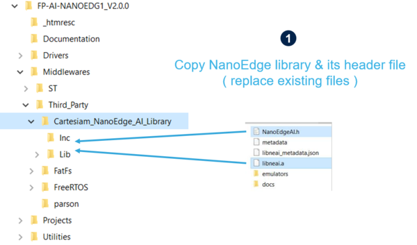
Once the libraries are generated and downloaded from Cartesiam NanoEdge AI Studio, the next step is to incorporate these libraries to FP-AI-NANOEDG1. The FP-AI-NANOEDG1, comes with the library stubs in the place of the actual libraries generated by NanoEdge AI Studio. This is done to make it easy for users to link the generated libraries and have a place holder for the libraries, which are generated by following the steps provided in the previous section. In order to link the actual libraries, the user needs to copy the generated libraries and replace the existing stub/dummy libraries and header files NanoEdgeAI.h, and libneai.a files present in the folders Inc, and lib, respectively. The relative paths of these folders are /FP_AI_NANOEDG1_V2.0.0/Middlewares/Third_Party/Cartesiam_NanoEdge_AI_Library/ as shown in the figure below.
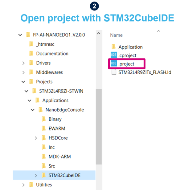
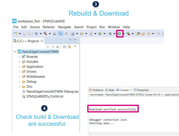
Once these files are copied, the project must be reconstructed and programmed on the sensor board to link the libraries. For this, the user needs to open the .project file from the FP-AI-NANOEDG1 folder, located at the path /FP_AI_NANOEDG1_V2.0.0/Projects/STM32L4R9ZI-STWIN/Applications/NanoEdgeConcole/STM32CubeIDE/ as shown in the step 2 in figure below.
To install the new firmware after linking the library, connect the sensor board, and rebuild the project using the play button. See the console for the outputs and wait for the Build and Download success message as shown in step 4 in the figure below.
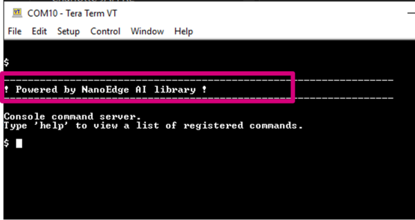
Once the sensor-board is programmed successfully, the following welcome message will appear in the CLI (Tera Term terminal). If the message does not appear you can try to reset the board by pressing the RESET button.
5.3. Testing the NanoEdgeAI Machine Learning library
Once the STWIN is programmed with the FW with a valid library, the condition monitoring libraries are ready to be tested on the sensor board.
The learning phase can be started by simply issuing a command start neai_learn in the CLI console. Starting this command will show the process of learning and will show a message on the console every time learning is performed on a new signal, as shown in the below snippet.
$ start neai_learn
NanoEdgeAI: starting

$ {"signal": 1, "status": success}
{"signal": 2, "status": success}
{"signal": 3, "status": success}
{"signal": 4, "status": success}
{"signal": 5, "status": success}
{"signal": 6, "status": success}
{"signal": 7, "status": success}
{"signal": 8, "status": success}
{"signal": 9, "status": success}
The process can be stopped either by issuing the
$ stop
command or by simply pressing the ESC key on the keyboard.
The learning can also be started by performing a long-press of the user button. Once the learning is happening, pressing the user button again will stop the learning process.
Once the normal conditions are learned, the user can start the condition monitoring process by starting the neai_detect mode.
This mode can be started by issuing the command
$ start neai_detect
NanoEdgeAI: starting
or by short pressing the user button on the sensor board. If the similarity of the current signal will be less than the threshold, the similarity will be printed on the CLI console showing the signal is an anomaly as shown in the snippet below. Nothing will be printed in the CLI console if the similarity is higher than 90% to the normal signals. Other than this the orange LED will blink fast (alternating 200 msec on-off sequence) to show the anomaly is detected.
5.3.1. Some hyper-parameters in condition monitoring
For the convenience of the users, the CLI application also provides some handy options to fine-tune the inference and learning process of the condition monitoring easily. Users can see all the variables they can play with by issuing the following command:
$ neai_get all
NanoEdgeAI: signals = 0
NanoEdgeAI: sensitivity = 1.000000
NanoEdgeAI: threshold = 95
NanoEdgeAI: timer = 0
Each of the these parameters can be configured using neai_set <param> <val> command. The details are provided in the command table above.
This section provides small details on neai_set signals <nr of signals> . Using this command, a user can start the learning or condition monitoring mode for a given number of samples. For example, to learn on 100 signals, the user can issue this command, before issuing the learn command. In the following snippet, an example is presented where the learning is performed for 10 signals.
$ neai_set signals 10
NanoEdge AI: signals set to 10

$ start neai_learn
NanoEdgeAI: starting

$ {"signal": 1, "status": success}
{"signal": 2, "status": success}
{"signal": 3, "status": success}
{"signal": 4, "status": success}
{"signal": 5, "status": success}
{"signal": 6, "status": success}
{"signal": 7, "status": success}
{"signal": 8, "status": success}
{"signal": 9, "status": success}
{"signal": 10, "status": success}
NanoEdge AI: stopped
The threshold parameter is used to report the anomalies. For any signal which has similarities below the threshold value is reported as anomaly. The default value used in the CLI application is 90. Users can change this value by using neai_set threshold <val> command.
The sensitivity parameter is used as an emphasis parameter. The default value is set to 1. Increasing this sensitivity will mean that the matching of the signals is to be performed more strictly, reducing it will also reduce the matching calculation process, i.e. resulting in higher matching values.
For details, users are invited to read the detailed documentation of NanoEdge AI studio.
6. Autonomous modes
The FP-AI-MONITOR1 is equipped with a button-operated mode to facilitate the users. The purpose of the button operated mode is to enable the users to operate the FP-AI-MONITOR1 even in the absence of the CLI console. All the (default) values required for running different functions are provided in the FW.
6.1. Button-operated mode
In the button-operated mode, the user can start-stop different execution phases using just the user button. The following table shows the user instruction for the button-operated mode.
| Button Press | Description | Action |
|---|---|---|
| SHORT_PRESS | The button is pressed for less than (200 ms) and released | Run the inference |
| LONG_PRESS | The button is pressed for more than (200 ms) and released | Starts the learning (Only when NanoEdgeTM AI Library is selected) |
| ANY_PRESS | The button is pressed and released (overlaps with the two other modes) | Stops the current running execution phase. |
The status of the current execution phase is indicated to the user through the onboard LEDs. The LEDs are allocated as the table below:
| Pattern | Green | Orange |
|---|---|---|
| OFF | Power OFF | |
| ON | idle | System error |
| BLINK | - | MicroSD™ card missing |
| BLINK_SHORT | Detecting, no anomaly | Anomaly detected |
| BLINK_LONG | Learning, status OK | Learning, status FAILED |
- DB4196: Artificial Intelligence (AI) condition monitoring function pack for STM32Cube
- User Manual : User Manual for FP-AI-NANOEDG1 V2.0
- Wiki: How to perform condition monitoring on STM32 using FP-AI-NANOEDG1
- Getting Started with FP-AI-NANOEDG1: Getting Started with FP-AI-NANOEDG1 V1.0, at STM32L562E-DK
- STEVAL-STWINKT1B
- DB4345: Data brief for STEVAL-STWINKT1B.
- UM2777: How to use the STEVALSTWINKT1B SensorTile Wireless Industrial Node for condition monitoring and predictive maintenance applications.
