| Coming soon |
Target description
This tutorial will help you to:
- Use the X-NUCLEO-SRC1M1 shield that includes a TCPP02-M18 protection circuit and provides a USB Type-C® connector
- Create a USB-PD Source Device with the NUCLEO-G0B1RE board and the X-NUCLEO-SRC1M1 shield by using STM32CubeIDE software
Prerequisites
- Computer with Windows 7 (or higher)
- Computer with Windows 7 (or higher)
Hardware
- NUCLEO-G0B1RE (tested on rev ???) [1]
- X-NUCLEO-SRC1M1 (tested on Rev ???) [2]
- USB cable Type-A to Micro-B
- USB Type-C® to Type-C® cable
- A USB-PD sink device to test our USB-PD device
Software
- STM32CubeIDE (tested with V1.7.0) [3]
Literature
- UM2324 NUCLEO-G0B1RE User Manual
1. Create a USB-PD Source Device
1.1. Creating the project
Open STM32CubeIDE and create a New STM32 Project. As a target selection, choose the NUCLEO-G0B1RE from the "Board Selector" Tab
Click "Next", then enter you project's name. Leave the other fields as default and click "Finish".
1.2. Configuring the project
When prompted for initializing peripherals with their default mode, click No.
At this point your project is created and you are left with the STM32CubeMX view.
In the next steps, we will configure the peripherals and options needed for the project.
1.2.1. Configure UCPD peripheral
Select the UCPD1 peripheral and enable it in source mode. Under the NVIC Settings tab, enable USB global interrupts.
Under the DMA Settings tab, add UCPD1_RX and UCPD1_TX DMA requests.
1.2.2. Configure FreeRTOS Middleware
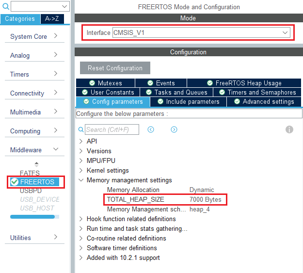
In the Middleware section, enable FreeRTOS with CMSIS_V1 interface. Under the Config Parameters tab, change "TOTAL_HEAP_SIZE" to 7000 bytes.
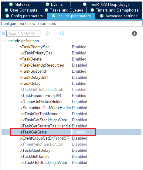
Then, under the Include Parameters tab, Enable "eTaskGetState" include definition.
1.2.3. Configure USBPD Middleware
In the Middleware section, enable USBPD with the following configuration:
- Port Configuration: Port 0: UCPD1
- Stack Configuration: PD3 Full Stack
- Timer service Source: TIM1
Under the PDO General Definitions tab, verify the following configuration:
- Number of Sink PDOs for port 0: 1
- Port 0 Sink PDO 1 0x2201912C (correspond to a 5V 3A source)
1.2.4. Configure ADC peripheral
In order for the Power Delivery stack to work, VBUS needs to be monitored. To do it, an ADC needs to be configured to measure the VBUS voltage.
In the Analog section, select ADC1 channel 0. You will then see pin PA0 turn green in the Pinout view.
Under the Parameters Settings tab, configure the following fields:
- Clock prescaler : Synch / 4
- Enable Continuous conversion
- Overrun data overwritten
- Sampling time: 160.5 Cycles
Under the GPIO Settings tab, rename pin PA0 to VSENSE, a more descriptive name for the pin used for VBUS monitoring.
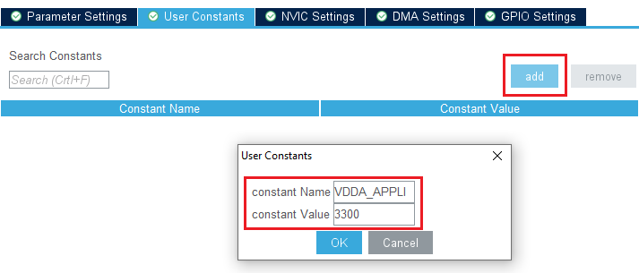
Then, under the USer Constants tab, add a constant named "VDD_APPLI" of value "3300".
1.2.5. Configure Clocks
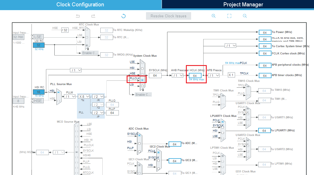
Under the Clock Configuration main tab, change system clock mux to PLLCLK. It will set HCLK clock to 64MHz.
1.2.6. [OPTIONAL] Configure Tracer for debug
1.2.6.1. Configure LPUART
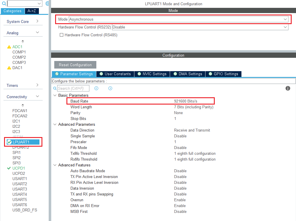
On the STM32G0 Nucleo-64 board, the Virtual COM port connected to the ST-LINK is the LPUART1.
In the Connectivity section, enable LPUART1 in Asynchronous mode, and baudrate 921600 bauds. Leave the rest as default.
In the pinout view, right click PA2 and PA3 to remap them to LPUART1_TX and LPUART1_RX.
Under the DMA Configuration tab, add a request for LPUART1_TX.
Finally, under the NVIC Settings tab, enable LPUART1 global interrupts.
1.2.6.2. Configure embedded tracer
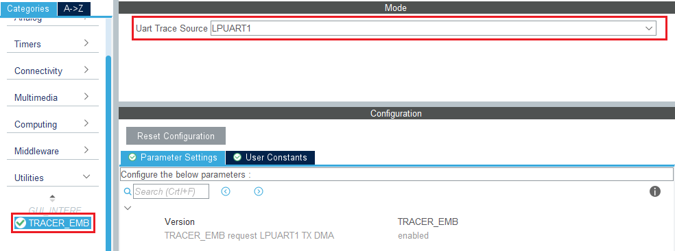
In the Utilities section, select TRACER_EMB and use LPUART1 as the trace source.
Then, go back to the USBPD middleware configuration and check the Tracer Source checkbox.
1.2.7. Configure UCPD monitor firmware responder for debug
The firmware interactive stack responder can be activated if interaction with the USB-PD stack is needed, using the UCPD monitor tool STM32CubeMonUCPD. In the Utilities section, enable GUI_INTERFACE, then enter free text to describe the board.
1.3. Configure project
Once the configuration is finished, few parameters must be saved in the project manager tab before saving the project.
Under the project manager tab, select a name for the project. For the project directory, avoid using One drive, if STM32CubeMX is not in One drive too.
Configure the minimum stack size to 0xC00. This is the first version, which can be tuned later, depending on the application needs.
In the Code Generator tab, STMicroelectronics recommends checking the Add necessary library files as reference tab.
In the Advanced Settings tab, change LPUART driver to LL to save a bit of memory heap size.
1.4. Generate code
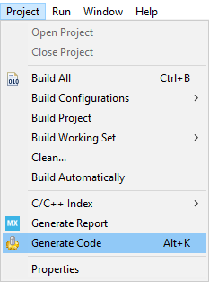
Save your file with Ctrl+s and select generate code if prompted. You can also generate code from the STM32CubeIDE menu by clicking Project/Generate Code, or by pressing Alt+K.
A warning appears, informing that a proper HAL timebase is not defined. It is safer to use a dedicated timer as a HAL timebase source.
For this demonstration, the below warning can be ignored by clicking Yes.
1.5. Compilation of generated application
The compilation must be performed without error or warning.
Build the application by clicking on the ![]() button.
button.
In this project, different folders can be found:
- The USBPD folder contains the source files that we need to edit to enrich the Power Delivery application.
- The Core folder contains the source files for the core of the project.
- The Drivers folder contains the HAL drivers for the STM32.
- The Middleware folder contains the source files and the libraries for FreeRTOS™ and USB-PD.
- The Utilities folder contains the GUI (UCPD monitor) and tracer embedded source files part.
1.6. Complete USB-PD application
Now that the peripherals are initialized by STM32CubeMX, some minimum level of the application needs to be added:
- ADC needs to be calibrated, and conversion needs to start.
- Fill the handlers for the interrupts to wake up the UCPD peripheral.
- Fill BSP_USBPD_PWR_VBUSGetVoltage function with the right coefficient depending on the VBUS divider bridge.
- Complete USBPD_DPM_SNK_EvaluateCapabilities to answer one source capability message.
- TCPP01‑M12 dead battery pin needs to be disabled, GPIO driven HIGH, to see the source Rp, or the jumper has to be set on the shield.
1.6.1. Modification in main.c
In this file, the ADC must start after its calibration, using HAL. The ADC is needed to read VBUS.
Code to be added between USER CODE ADC1_Init 2 tags:
…
  /* USER CODE BEGIN ADC1_Init 2 */
  HAL_ADCEx_Calibration_Start(&hadc1);
  HAL_ADC_Start(&hadc1);
  /* USER CODE END ADC1_Init 2 */
…
Note: For STM32G4, ADC calibration API is different, the calibration line must be replaced by:
HAL_ADCEx_Calibration_Start(&hadc1, sConfig.SingleDiff);
Note: This simple example is not optimized from a power point of view, as the ADC is always running.
1.7. References
- ↑ NUCLEO-G0B1RE
- ↑ [??? ???]
- ↑ STM32CubeIDE
