This article gives an overview of the OEMiRoT solutions integrated in STM32H7R.
List of applicable products:
| Type | Products |
|---|---|
| Microcontroller | STM32H7R7A8, STM32H7R7I8, STM32H7R7L8, STM32H7R7N8 STM32H7R7Z8, STM32H7R3A8, STM32H7R3I8, STM32H7R3L8, STM32H7R3L8U, STM32H7R3N8, STM32H7R3R8, STM32H7R3V8, STM32H7R3Z8 |
1. OEMiRoT presentation
1.1. Overview
OEMiRoT stands for OEM immutable (unchangeable) Root of Trust and acts as a first boot stage. OEMiRoT is an example based on the MCUboot open-source software (refer to MCUboot) provided with STM32CubeH7RS. OEMiRoT offers two services:
- The Secure Boot (root of trust service) is an immutable code, which is always executed after a system reset. It checks static protections (options bytes), activates runtime protections, and then verifies the authenticity and integrity of the user application code before every execution.
- The Secure Firmware Update application is an immutable code that detects new firmware image candidate. It checks its version (version downgrade prevention), authenticity, and integrity before installing it after decryption.
1.2. About hardware
- Contrary to STM32H7S, STM32H7R doesn’t support hardware cryptography (CRYP, PKA and, consequently MCE).
- STiRoT is not supported either (the Option Byte IROT_SELECT is irrelevant on STM32H7R).
- STM32H7R OEMiRoT solution relies on software cryptography.
Note: for more details about difference beteween STM32H7S and STM32H7R, see STM32H7RS Reference manual
1.3. Protection measures and security strategy
Cryptography ensures integrity, authentication, and confidentiality. However, the use of cryptography alone is not enough: a set of measures and system-level strategies are needed for protecting critical operations, sensitive data (such as a secret key), and the execution flow in order to improve security robustness. On STM32H7R, the security strategy is based on:
- Product life cycle: product state CLOSED or LOCKED must be selected in order to ensure that the JTAG debugger cannot access the device, except to execute the DA process (more details in Debug Authentication for STM32H7RS wiki article).
- Boot configuration: On STM32H7R, the system always boot on user flash memory:
- One boot stage: IROT_SELECT option byte is still set to OEMiRoT for compliance with STMH7S configuration. However, on STM32H7R, this configuration is ignored. For more details, see STM32H7RS Reference manual
- Antitamper protection: the antitamper protection is used to protect sensitive data from physical attacks. The antitamper protection is activated at the start of OEMiRoT_Boot project and remains active during OEMiRoT_Appli execution. In case of tamper detection, sensitive data, caches, and a reboot is forced. Both external active tamper pins and internal tamper events are used.
- MPU: The MPU is a memory protection mechanism that allows specific access rights to be defined for any memory-mapped resources of the device: flash memory, SRAM, and peripheral registers. The MPU is configured to limit the execution surface to the code section of OEMiRoT_Boot project during its execution, then extended to the application code section after verifying its integrity and its authenticity. This protection is dynamically managed at runtime.
- HDP: HDP area is configured to cover the whole OEMiRoT_Boot project code area in order to prevent any execution out of the OEMiRoT_Boot execution. When jumping in the application, the temporal isolation (HDP level) is increased from HDPL1 to HDPL3 making the OEMiRoT_Boot project code no longer accessible.
- OBkeys: HDPL1 OBkeys are a protected and isolated area used to store secrets such as encryption and authentication cryptographic keys. This area is no longer accessible when switching from HDPL1 to HDPL2 or to HDPL3.
- WRP: Write protection is used to ensure OEMiRoT_Boot code immutability as requested by the state-of-the-art standards in secure boot implementation. In the OEMiRoT_Boot project, the system has been configured to make the OEMiRoT_Boot code as immutable.
- RAM ECC: RAM ECC is a mechanism to prevent memory corruption. A reset is generated in case of RAM ECC detection.
See also STM32H7RS Reference manual for more description on each feature.
1.4. OEMiRoT activation
On STM32H7R, OEMiRoT activation is done by:
- Configuring secrets: authentication and encryption keys used by OEMiRoT.
- Building OEMiRoT_Boot binary in OEMiRoT.
All these operations are part of the provisioning process.
There is only one use case:
- One boot stage, OEMiRoT: OEMiRoT_Boot project binary is built in OEMiRoT configuration. OEMiRoT directly manages the user application binary.
See also Secure Boot and Secure Firmware Update for STM32H7RS article.
1.4.1. One boot stage: OEMiRoT
OEMiRoT is generated by compiling OEMiRoT_Boot project with the OEMUROT_ENABLE switch de-activated.
At reset, OEMiRoT, located in the user flash memory, is executed in temporal isolation 1 (HDPL1). After a successful verification of the authenticity and the integrity of the user application code image, OEMiRoT executes the user application in HDPL3. In case of verification failure, a reset will be triggered except if OEMIROT_DEV_MODE compilation switch is activated during OEMiRoT_Boot project generation. In this case the execution will fall into an infinite loop.
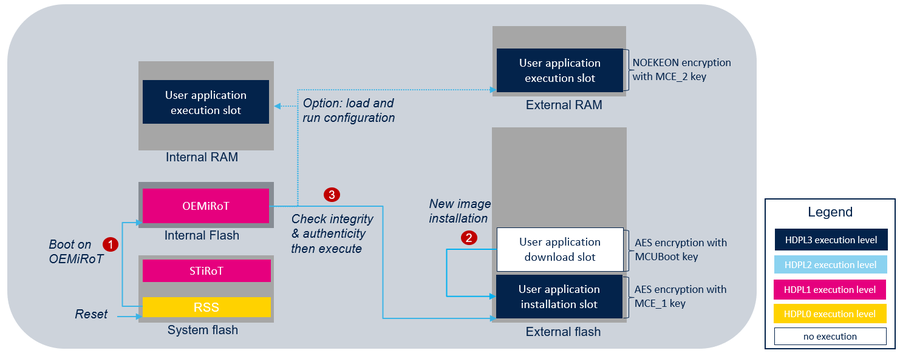
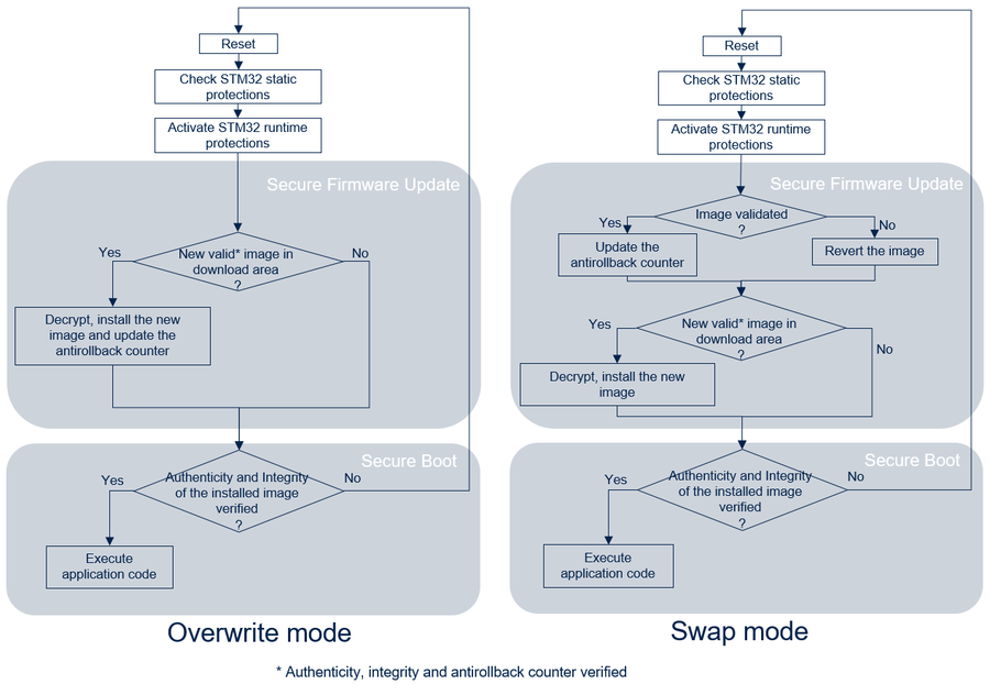
The following figure illustrates the secure boot and the secure update process by showing all the steps required to boot the user application code image located in the installation slot of the external flash memory:
- In CLOSED or LOCKED product state, RSS is the first software executed. RSS jumps into OEMiRoT.
- OEMiRoT checks if a new user application is stored in the download slot. If any, OEMiRoT decrypts it then controls its integrity, its authenticity and the antirollback version. If successful, the image is decrypted and copied in the user application installation slot.
- OEMiRoT controls the integrity and the authenticity of the user application image from the installation slot located in the external flash memory. If successful, OEMiRoT executes it from external flash memory or from external/internal RAM memories. (Coming soon) In case of RAM memory execution (load and run use case), an additional copy is made before its execution. Refer to the Features list for more details on OEMiRoT execution modes. (coming soon: diagram)
Note: To ensure the security of the device, the MPU is configured to allow only the user application code area to be executed when OEMiRoT jumps into the user application, minimizing the risk of unauthorized code execution. It is the user application responsibility to reconfigure the MPU to fit with its security needs.
1.4.2. Swap upgrade strategy
When the swap upgrade strategy is configured when generating OEMiRoT, the scratch buffer is used:
- during installation, to swap download and installation slots.
- at reset, the images are swapped back if the new user application is not confirmed. (coming soon: diagram)
In the swap upgrade strategy, the antirollback version is saved at reset if the user application is confirmed. However, in overwrite mode, it is saved at the end of the installation process. Refer to OEMiRoT start-up sequence for more details.
2. Features list
The main features of the OEMiRoT are:
- Accelerated boot thanks to image SHA256 reference management. Image verification mainly consists of verifying the SHA256 of the image (integrity check), and then verifying the signature of this SHA256 (authentication check). If successful, the SHA256 is stored as reference for next boot. At the next boot, the signature verification is skipped if the SHA256 of the image match the reference stored in OBKeys. This feature brings performance optimization (under the MCUBOOT_USE_HASH_REF compilation switch).
- Antirollback version check based on image version stored in OBkeys.
- Image installation resistant to asynchronous power down and reset.
- Integration of the full entropy TRNG source (RNG hardware peripheral) for random delays generation.
- Configurable firmware image upgrade strategy for primary and secondary slots mode:
- Overwrite strategy, for which the image in the secondary slot overwrites the image in the primary slot.
- Swap strategy, for which the image in primary and secondary slots are swapped. After the swap, the new image in the primary slot must be confirmed by the user application. Otherwise, at the next boot, the images are swapped back.
- Note: A reset must be generated by the user application after confirmation to update the confirmation flag inside the image in the installation slot. The "read while write" feature is not managed for the external flash memory.
- Memory configuration:
- Download slot in external flash memory. The image is encrypted in AES-CTR-128 with a symmetric key. This key is encrypted in ECIES-P256 with MCUBootkey.
- Installation slot in external flash memory.
- (Coming soon) Load and run execution mode capability is configured with OEMIROT_LOAD_AND_RUN define. In addition to the standard execution mode (in place), the user application can be executed:
- from internal RAM memory
- Integration of hardware security peripherals and mechanisms in order to implement a root of trust. Product life cycle, MPU, WRP, HDP, and TAMPER are combined to protect the product. When connected on the HW board, external tamper can be activated with OEMIROT_TAMPER_ENABLE define.
- Image generation with STM32TrustedPackageCreator tool delivered within STM32CubeProgrammer.
Features configurability:
| Feature | OEMiRoT |
|---|---|
|
Boot project generation |
OEMiRoT generation |
|
Image upgrade strategy |
|
|
Flash memory configuration |
|
|
Load and run execution modes configuration |
|
|
Antitamper |
|
|
Project phase (Application development phase ) |
|
3. Memories layout
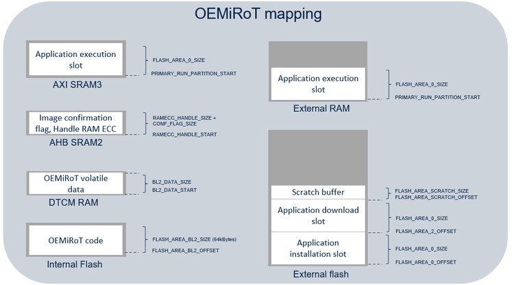
The STM32CubeH7RS OEMiRoT relies on memories layout defining several regions:
- SCRATCH region: region used by OEMiRoT_Boot to store the image data temporarily during the image swap process (not used in overwrite-only mode).
- OEMiRoT_Boot code region: region to program the OEMiRoT_Boot code binary that manages the functions "Secure Boot" and "Secure Firmware Update”.
- OEMiRoT_Boot volatile data: region used to locate internal variables and call stack, during OEMiRoT_Boot code execution.
- Application installation (primary) slot region: region to program the image of an “active” firmware after installation.
- Application download (secondary) slot region: region to program the image of a “new” firmware, candidate for installation.
- Application execution slot region when load and run feature is activated. (Coming soon)
- Image confirmation flag and RAM ECC handle.
Memories layout is as follow: (coming soon)
For both configuration, default values are:
| Symbol | Execute in place | Load and run in external RAM | Load and run in internal RAM |
|---|---|---|---|
| FLASH_AREA_0_OFFSET | 0x00000000 | 0x00000000 | 0x00000000 |
| FLASH_AREA_0_SIZE | 0x00200000 | 0x00200000 | 0x00020000 |
| FLASH_AREA_2_OFFSET | 0x00200000 | 0x00200000 | 0x00020000 |
| FLASH_AREA_2_SIZE | 0x00200000 | 0x00200000 | 0x00020000 |
| PRIMARY_RUN_PARTITION_START (coming soon) | NA | 0x90000000 | 0x24040000 |
| FLASH_AREA_SCRATCH_OFFSET | 0x00400000 | 0x00400000 | 0x00040000 |
| FLASH_AREA_SCRATCH_SIZE | 0x00010000 | 0x00010000 | 0x00010000 |
| FLASH_AREA_BL2_OFFSET | 0x00000000 | 0x00000000 | 0x00000000 |
| FLASH_AREA_BL2_SIZE | 0x00010000 | 0x00010000 | 0x00010000 |
| BL2_RAM_BASE | 0x24000000 | 0x24000000 | 0x24000000 |
| BL2_RAM_SIZE | 0x00020000 | 0x00020000 | 0x00020000 |
| BL2_DATA_START | 0x20000000 | 0x20000000 | 0x20000000 |
| BL2_DATA_SIZE | 0x00020000 | 0x00020000 | 0x00020000 |
| RAMECC_HANDLE_START | 0x30004000 | 0x30004000 | 0x30004000 |
| RAMECC_HANDLE_SIZE | 0x40 | 0x40 | 0x40 |
| CONF_FLAG_SIZE | 0x20 | 0x20 | 0x20 |
If the definition of the FLASH_AREA_0 or FLASH_AREA_2 is modified (offset or size), the MPU regions configuration must be updated taking into account the constraints on Cortex M7 MPU (refer toARM documentation for more details):
- region start address is multiple of the region size
- each region can be divided in 8 sub-regions
4. Provisioning process
4.1. OEMiRoT provisioning process
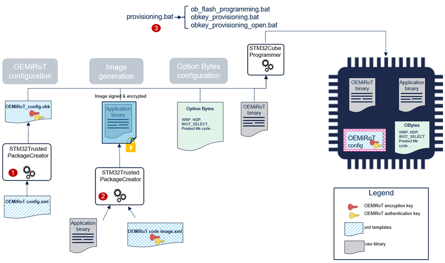
The product provisioning to activate and configure OEMiRoT is done following the three steps below:
- Configuration of OEMiRoT. At this stage, the cryptographic keys for authentication and encryption are defined.
- Generation of the firmware image.
- Programming of the OBkeys, the option bytes, the application image in the device.
Note: A set of scripts is provided in Firmware/Projects/STM32H7S78-DK/ROT_Provisioning/OEMiRoT folder. It guides the user all along the provisioning process. Refer to How to start with OEMiRoT on STM32H7S article.
4.2. OEMiRoT configuration file
OEMiRoT configuration file (OEMiRoT_Config.obk) is generated using STM32TrustedPackageCreator with a template file listing all the different parameters (OEMiRoT_Config.xml) as input. The obk file is saved in HDPL1 OBkeys.
The list of the configuration parameters is the following:
| Parameter | Description | Additional constraints |
|---|---|---|
| Authentication key | Key used to authenticate the firmware image | When this key is regenerated, firmware image must be processed with TPC “Image Gen” tab (OEMiRoT_Code_Image.xml) |
5. Image generation
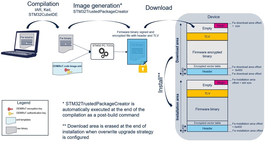
OEMiRoT manages an image based on MCUBoot format including:
- a header,
- the encrypted firmware binary,
- some metadata information (TLV format: Tags Length Value) allowing the control of the image (SHA256, ECDSA-P256 signature…), and
- a magic to trigger the installation at the end of the slot.
Further information about the MCUBoot open-source software is available at MCUboot.
A PC tool STM32TrustedPackageCreator is provided to generate the firmware code image. This image is encrypted and signed using the keys configured in OBkeys configuration file (OEMiRoT_Config.xml). OEMiRoT_Code_Image.xml contains all the parameters driving the image generation such as:
- The authentication and encryption keys. Keys value inherited from OEMiRoT_Config.xml.
- The version. OEMiRoT_Code_Image.xml can be edited with STM32TrustedPackageCreator in order to modify the version.
The following figure shows the firmware image generation:
6. Hardware setup
6.1. Configuration for Discovery boards
This part stands for the switch from STM32H7S78-DK to STM32H7R78-DK.
The project STM32H7S78-DK can be tailored to to run as STM32H7R78-DK project. So, it can be used with a STM32H7R78-DK board. This switch is supported only by IAR and KEIL. To switch from STM32H7S78-DK to STM32H7R78-DK follow these steps:
- Open the STM32H7S78-DK\Applications\ROT\OEMiROT_Boot project:
- with IAR (EWARM):
- Go to "Options" and select "General Options" then in the "Target" field Select "device" to choose your device.
- Go to "Options" and select "C/C++ Compiler" then "Preprocessor" tab and change the compilation symbol (STM32H7R7xx instead of STM32H7S7xx).
- Open the "prebuild.cmd" file (located in "Firmware/Projects/STM32H7S78-DK/Applications/ROT/OEMiROT_Boot/EWARM") and change the compilation symbol (-DSTM32H7R7xx instead of -DSTM32H7S7xx).
- with KEIL (MDK-ARM):
- Go to "Options" and select "Device" tab to choose your device.
- Go to "Options" and select "C/C++ (AC6)" tab then in the "Define" field in "Preprocessor Symbols" and change the compilation symbol (STM32H7R7xx instead of STM32H7S7xx).
- Go to "Options" and in the "User" tab change "Run #2" command in the "Before Build/Rebuild" field and add the define of your platform ("-DSTM32H7R7xx" instead of "-DSTM32H7S7xx").
- with IAR (EWARM):
- Update STM32H7S78-DK\ROT_Provisioning files:
- STM32H7S78-DK\ROT_Provisioning\env.bat (.sh):
- update stm32tool_path if the default path ("C:\Program Files\STMicroelectronics\STM32Cube\STM32CubeProgrammer\bin") is not correct
- update stm32ExtLoaderFlash with "-elbl %stm32tool_path%/ExternalLoader/MX66UW1G45G_STM32H7S78-DK-SFIx.stldr"
- update stm32ExtLoaderFlashOpen with "-elbl %stm32tool_path%/ExternalLoader/MX66UW1G45G_STM32H7S78-DK.stldr"
- update com_port with your board correct com port number. It can be know by using Windows device manager as shown in figure below:
- STM32H7S78-DK\ROT_Provisioning\OEMiROT\obkey_provisioning.bat, obkey_provisioning_open.bat, provisioning.bat (.sh):
- update device_type with "H7R"
- STM32H7S78-DK\ROT_Provisioning\DA\Config\DA_Config.xml, DA_ConfigWithPassword.xml:
- use a text editor to set the field DoEncryption to 0 and use STM32TrustedPackageCreator to generate matching .obk files
- STM32H7S78-DK\ROT_Provisioning\OEMiROT\Config\OEMiROT_Config.xml:
- use a text editor to set the field DoEncryption to 0 and use STM32TrustedPackageCreator to generate matching .obk files
- STM32H7S78-DK\ROT_Provisioning\env.bat (.sh):
6.2. Configuration for NUCLEO boards
This part stands for the switch from STM32H7S78-DK to NUCLEO-H7R3L8
7. Appendix
7.1. OEMiRoT start-up sequence
Note: When no valid firmware image is installed a reset will be triggered in loop. Debug authentication process must be executed to force the download of a new image. Refer to Debug Authentication for STM32H7RS article.
Performance measured @ 380 MHz:
| Configuration | User application boot time | ||
|---|---|---|---|
| 1 Mbytes | 2 Mbytes | 3 Mbytes | |
| Execution from external flash | x ms | x ms | x ms |
| Execution from internal RAM memory (Coming soon) | x ms | x ms | x ms |
7.2. Application development phase
During development phase, it is recommended to compile OEMiRoT_Boot project with DEV_MODE defined and to select OPEN state during provisioning process:
- When DEV_MODE is defined:
- logs are displayed in tera term during OEMiRoT_Boot project execution.
- an infinite loop is executed instead of a reset in Error_Handler() function.
- tamper event is cleared at startup when required. No need to power off/on the board to clear this event.
- OPEN product state can be selected during provisioning process.
- When OPEN product state is selected during provisioning process, a specific script (obkey_provisioning_open.bat) is called in order to execute additional actions usually done in PROVISIONING product state:
- provision the AHKs (see STM32H7RS Reference manual for more description) used to encrypt OBkeys and to encrypt images with MCE peripheral.
- initialize the OEMiRoT data area in the OBkeys containing the version of the firmware installed as well as its SHA256 used when MCUBOOT_USE_HASH_REF is activated. Refer to the Features list for more details on MCUBOOT_USE_HASH_REF.
In CLOSED or LOCKED product state, the DA process should be run to be able to connect the debugger trough JTAG. At the end of the development phase, DEV_MODE must be disabled and the product state CLOSED or LOCKED must be selected during provisioning process. Refer to Debug Authentication for STM32H7RS article.
7.3. OEMiRoT_Config.obk file format
| Offset | Size | Type | Description |
|---|---|---|---|
| 0 | 1 | uint8 | sdp command header : destination OBKey index |
| 1 | 1 | uint8 | sdp command header : destination OBKey HDP level |
| 2 | 2 | uint16 | sdp command header : reserved |
| 4 | 4 | uint32 | sdp command header : data size |
| 8 | 4 | uint32 | sdp command header : encryption always disabled for STM32H7R (0) |
| 12 | 32 | array | SHA256 of the following data content (from offset 44 to 235) |
| 44 | 91 | array | ECDSA-P256 authentication public key |
| 135 | 70 | array | ECDSA-P256 encryption private key |
| 205 | 31 | array | Reserved |
7.4. OEMiRoT_Code_image xml file format
| Parameter | Updatable | Description |
|---|---|---|
| Authentication key | Automatic | Private key inherited from OEMiROT_Config.xml file. |
| Encryption key | Automatic | Public key inherited from OEMiROT_Config.xml file. |
| Endianness | No | Little endian. |
| Padding | No | Add an installation magic value at the end of the image to trigger image installation. Padding with 0xFF when required. |
| Firmware area size | Automatic | Firmware slot size information. This value is updated during the postbuild of OEMiRoT_Boot project compilation based on slot configuration from flash_layout.h |
| Header Size | No | 0x400 bytes |
| Padding Header | No | Padding the header with 0xFF to fulfil the 0x400 bytes. |
| Dependency with data image | No | The dependency is disabled by setting the <enable> property to 0. |
| Write Option | Automatic | Image upgrade strategy: Overwrite, Swap. This value is updated during the postbuild of OEMiRoT_Boot project compilation based on MCUBOOT_OVERWRITE_ONLY definition from flash_layout.h. |
| Version | Yes | x.y.z firmware image version. |
| Security Counter | No | Security counter value automatically generated based on version information. |
| Align | No | The size of the encrypted binary generated is multiple of 16 bytes. |
| Firmware download area offset | Automatic | Used to generate .hex binary file format including the destination address. This value is updated during the postbuild of OEMiRoT_Boot project compilation based on slot configuration from flash_layout.h. |
| Firmware binary input file | Automatic | Location of the firmware binary file. This parameter is updated during the provisioning process based on information from env.bat file. |
| Image output file | Yes | Location of the encrypted image generated. If changed, provisioning scripts must be updated accordingly. |
