Sensing and condition monitoring are two of the major components of the IoT and predictive maintenance systems, enabling context awareness, production performance improvement, a drastic decrease of the downtime due to routine maintenance, and so, maintenance cost reduction.
The FP-AI-MONITOR1 function pack is a Multi-sensor AI data monitoring framework on wireless industrial node, function pack for STM32Cube. It helps to jump-start the implementation and development for sensor-monitoring-based applications designed with the X-CUBE-AI Expansion Package for STM32Cube or with the NanoEdge™ AI Studio. It covers the entire design of the Machine Learning cycle from the data set acquisition to the integration on a physical node.
The FP-AI-MONITOR1 runs learning and inference sessions in real time on the SensorTile Wireless Industrial Node development kit (STEVAL-STWINKT1B) , taking data from onboard sensors as input. The FP-AI-MONITOR1 implements a wired interactive CLI to configure the node, and manages the learn and detect phases. For simple in the field operation, a standalone battery-operated mode allows basic controls through the user button, without using the console.
The STEVAL-STWINKT1B has an STM32L4R9ZI ultra-low-power microcontroller (Arm® Cortex®‑M4 at 120 MHz with 2 Mbytes of Flash memory and 640 Kbytes of SRAM). In addition the STEVAL-STWINKT1B embeds industrial-grade sensors, including 6-axis IMU, 3-axis accelerometer and vibrometer to record any inertial and vibrational data with high accuracy at high frequencies.
The rest of the article discusses the following topics:
- The general information about the FP-AI-MONITOR1,
- Setting up the hardware and software components,
- Button operated modes,
- Command line interface (CLI),
- Human activity recognition, a classification application using accelerometer data,
- Anomaly detection using NanoEdge™ AI,
- Performing the data logging using onboard vibration sensors and a prebuilt binary of FP-SNS-DATALOG1, and
- Some links to useful online resources, to help a user to better understand and customize the project for specific needs.
1 General information
The FP-AI-MONITOR1 function pack runs on STM32L4+ microcontrollers based on Arm® cores.
1.1 Feature overview
- Complete firmware to program an STM32L4+ sensor node for sensor-monitoring-based applications on the STEVAL-STWINKT1B SensorTile wireless industrial node
- Runs classical Machine Learning (ML) and Artificial Neural Network (ANN) models generated by the X-CUBE-AI, an STM32Cube Expansion Package
- Runs NanoEdge™ AI libraries generated by NanoEdge™ AI Studio for AI-based sensing applications. Easy integration by replacing the pre-integrated stub,
- Application example of human activity classification based on motion sensors
- Application binary of high-speed datalogger for STEVAL-STWINKT1B data record from any combination of sensors and microphones configured up to the maximum sampling rate on a microSD™ card
- Sensor manager firmware module to configure any board sensors easily, and suitable for production applications,
- eLooM (embedded Light object-oriented fraMework) enabling efficient development of soft realtime, multi-tasking, eventdriven embedded applications on STM32L4+ Series microcontrollers
- Digital processing unit (DPU) firmware module providing a set of processing blocks, which can be chained together, to apply mathematical transformations to the sensors data,
- Configurable autonomous mode controlled by user button,
- Interactive command-line interface (CLI):
- Node and sensor configuration
- Configure application running either an [X-CUBE-AI ML or ANN model, or a NanoEdge™ AI Studio model with learn-and-detect capability
- Easy portability across STM32 microcontrollers by means of the STM32Cube ecosystem
- Free and user-friendly license terms
1.2 Software architecture
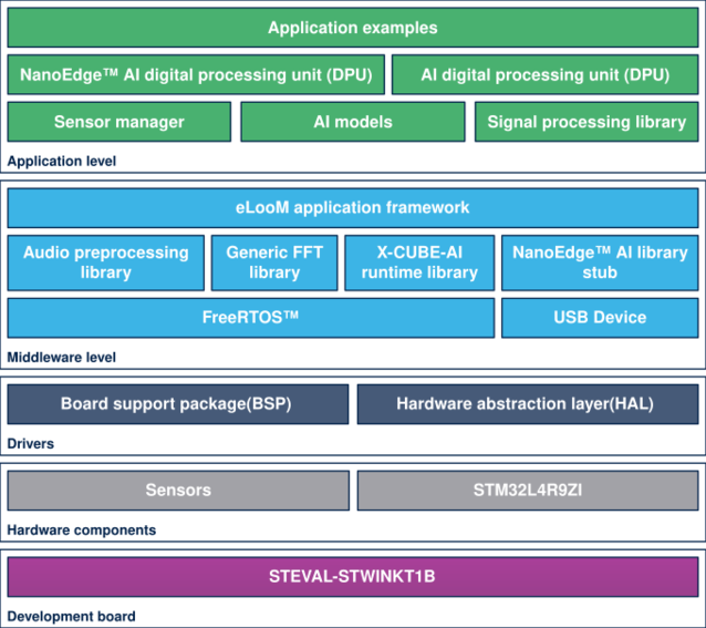
The top-level architecture of the FP-AI-MONITOR1 function pack is shown in the following figure.
The STM32Cube function packs leverage the modularity and interoperability of STM32 Nucleo and expansion boards running STM32Cube MCU Packages and Expansion Packages to create functional examples representing some of the most common use cases in certain applications. The function packs are designed to fully exploit the underlying STM32 ODE hardware and software components to best satisfy the final user application requirements.
Function packs may include additional libraries and frameworks, not present in the original STM32Cube Expansion Packages, which enable new functions and create more targeted and usable systems for developers.
STM32Cube ecosystem includes:
- A set of user-friendly software development tools to cover project development from the design to the implementation, among which are:
- STM32CubeMX, a graphical software configuration tool that allows the automatic generation of C initialization code using graphical wizards
- STM32CubeIDE, an all-in-one development tool with peripheral configuration, code generation, code compilation, and debug features
- STM32CubeProgrammer (STM32CubeProg), a programming tool available in graphical and command-line versions
- STM32CubeMonitor (STM32CubeMonitor, STM32CubeMonPwr, STM32CubeMonRF, STM32CubeMonUCPD) powerful monitoring tools to fine-tune the behavior and performance of STM32 applications in real-time.
- STM32Cube MCU & MPU Packages, comprehensive embedded-software platforms specific to each microcontroller and microprocessor series (such as STM32CubeL4 for the STM32L4+ Series), which include:
- STM32Cube hardware abstraction layer (HAL), ensuring maximized portability across the STM32 portfolio
- STM32Cube low-layer APIs, ensuring the best performance and footprints with a high degree of user control over the HW
- A consistent set of middleware components such as FreeRTOS™, USB Device, USB PD, FAT file system, Touch library, Trusted Firmware (TF-M), mbedTLS, Parson, and mbed-crypto
- All embedded software utilities with full sets of peripheral and application examples
- STM32Cube Expansion Packages, which contain embedded software components that complement the functionalities of the STM32Cube MCU & MPU Packages with:
- Middleware extensions and application layers
- Examples running on some specific STMicroelectronics development boards
To access and use the sensor expansion board, the application software uses:
- STM32Cube hardware abstraction layer (HAL): provides a simple, generic, and multi-instance set of generic and extension APIs (application programming interfaces) to interact with the upper layer applications, libraries, and stacks. It is directly based on a generic architecture and allows the layers that are built on it, such as the middleware layer, to implement their functions without requiring the specific hardware configuration for a given microcontroller unit (MCU). This structure improves library code reusability and guarantees easy portability across other devices.
- Board support package (BSP) layer: supports the peripherals on the STM32 Nucleo boards.
1.3 Folder structure
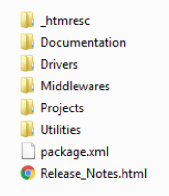
The figure above shows the contents of the function pack folder. The content of each of these subfolders is as follows:
- Documentation: contains a compiled
.chmfile generated from the source code, which details the software components and APIs. - Drivers: contains the HAL drivers, the board-specific drivers for each supported board or hardware platform (including the onboard components), and the CMSIS vendor-independent hardware abstraction layer for the Cortex®-M processors.
- Middlewares: contains libraries and protocols for ST parts as well as for the third parties. The ST components include the eLoom libraries, NanoEdge™ AI library stub, Audio Processing library, FFT library and USB Device library.
- Projects: contains a sample application software, which can be used to program the sensor-board for classification and anomaly detection applications using the data from the motion sensors and manage the learning and detection phases of NanoEdge™ AI library provided for the STEVAL-STWINKT1B platforms through the STM32CubeIDE development environment.
- Utilities: contains python scripts and sample datasets. These python scripts can be used to create Human Activity Recognition (HAR) models using Convolutional Neural Networks (CNN) or Support Vector machine based Classifier (SVC). The FP-AI-MONITOR1 also enables a user to prepare the data logged from the
HSDatalog.binfor the NanoEdge™ AI library generation.
1.4 Terms and definitions
| Acronym | Definition |
|---|---|
| API | Application programming interface |
| BSP | Board support package |
| CLI | Command line interface |
| FP | Function pack |
| HAL | Hardware abstraction layer |
| MCU | Microcontroller unit |
| ML | Machine learning |
| ODE | Open development environment |
1.5 References
| References | Description | Source |
|---|---|---|
| [1] | X-CUBE-AI | X-CUBE-AI |
| [2] | NanoEdge™ AI Studio | st.com/nanoedge |
| [3] | STEVAL-STWINKT1B | STWINKT1B |
1.6 Prerequisites
- One of the following IDEs must be installed:
- STMicroelectronics - STM32CubeIDE version 1.7
- IAR Embedded Workbench for Arm (EWARM) toolchain V8.50.9 or later
- RealView Microcontroller Development Kit (MDK-ARM) toolchain V5.31
- FP-AI-MONITOR1 can be deployed on the following operating systems:
- Windows® 10
- Ubuntu® 18.4 and Ubuntu® 16.4 (or derived)
- macOS® (x64)
- NanoEdge™ AI Studio for generating the condition monitoring libraries.
Note: Ubuntu® is a registered trademark of Canonical Ltd. macOS® is a trademark of Apple Inc. registered in the U.S. and other countries.
1.7 Licenses
FP-AI-MONITOR1 is delivered under the Mix Ultimate Liberty+OSS+3rd-party V1 software license agreement (SLA0048).
The software components provided in this package come with different license schemes as shown in the table below.
| Software component | Copyright | License |
|---|---|---|
| Arm® Cortex®-M CMSIS | Arm Limited | Apache License 2.0 |
| FreeRTOS™ | Amazon.com, Inc. or its affiiates | MIT |
| STM32L4xxx_HAL_Driver | STMicroelectronics | BSD-3-Clause |
| Board support package (BSP) | STMicroelectronics | BSD-3-Clause |
| STM32L4xx CMSIS | Arm Limited - STMicroelectronics | Apache License 2.0 |
| eLooM application framework | STMicroelectronics | Proprietary |
| Python TM scripts | STMicroelectronics | BSD-3-Clause |
| Dataset | STMicroelectronics | Proprietary |
| Sensor Manager | STMicroelectronics | Proprietary |
| Audio preprocessing library | STMicroelectronics | Proprietary |
| Generic FFT library | STMicroelectronics | Proprietary |
| X-CUBE-AI runtime library | STMicroelectronics | Proprietary |
| X-CUBE-AI HAR model | STMicroelectronics | Proprietary |
| NanoEdge™ AI library stub | STMicroelectronics | Proprietary |
| Signal processing library | STMicroelectronics | Proprietary |
| Digital processing unit (DPU) | STMicroelectronics | Proprietary |
| Trace analyser recorder | Percepio AB | Percepio Proprietary |
2 Hardware and firmware setup
2.1 HW prerequisites and setup
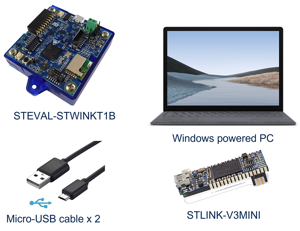
To use the FP-AI-MONITOR1 function pack on STEVAL-STWINKT1B, the following hardware items are required:
- STEVAL-STWINKT1B development kit board,
- Windows® powered laptop/PC (Windows® 7, 8, or 10),
- Two MicroUSB cables, one to connect the sensor-board to the PC, and another one for the STLINK-V3MINI, and
- an STLINK-V3MINI.
2.1.1 Presentation of the Target STM32 board
The STWIN SensorTile wireless industrial node (STEVAL-STWINKT1B) is a development kit and reference design that simplifies the prototyping and testing of advanced industrial IoT applications such as condition monitoring and predictive maintenance. It is powered with Ultra-low-power Arm® Cortex®-M4 MCU at 120 MHz with FPU, 2048 kbytes Flash memory (STM32L4R9). Other than this, STWIN SensorTile is equipped with a microSD™ card slot for standalone data logging applications, a wireless BLE4.2 (on-board) and Wi-Fi (with STEVAL-STWINWFV1 expansion board), and wired RS485 and USB OTG connectivity, as well as Brand protection secure solution with STSAFE-A110. In terms of sensor, STWIN SensorTile is equipped with a wide range of industrial IoT sensors including:
- an ultra-wide bandwidth (up to 6 kHz), low-noise, 3-axis digital vibration sensor (IIS3DWB)
- a 6-axis digital accelerometer and gyroscope iNEMO inertial measurement unit (IMU) with machine learning (ISM330DHCX)
- an ultra-low-power high-performance MEMS motion sensor (IIS2DH)
- an ultra-low-power 3-axis magnetometer (IIS2MDC)
- a digital absolute pressure sensor (LPS22HH)
- a relative humidity and temperature sensor (HTS221)
- a low-voltage digital local temperature sensor (STTS751)
- an industrial-grade digital MEMS microphone (IMP34DT05), and
- a wideband analog MEMS microphone (MP23ABS1)
Other attractive features include:
- – a Li-Po battery 480 mAh to enable standalone working mode
- – STLINK-V3MINI debugger with programming cable to flash the board
- – a Plastic box for ease of placing and planting the SensorTile on the machines for condition monitoring. For further details, the users are advised to visit this link
2.2 Software requirements
2.2.1 FP-AI-MONITOR1
- Download the FP-AI-MONITOR1, package from ST website, extract and copy the .zip file contents into a folder on the PC. The package contains binaries and source code, for the sensor-board STEVAL-STWINKT1B.
2.2.2 IDE
- One of the following IDEs must be installed:
- STMicroelectronics - STM32CubeIDE version 1.7.0,
- IAR Embedded Workbench for Arm (EWARM) toolchain version 8.50.9 or later,
- RealView Microcontroller Development Kit (MDK-ARM) toolchain version 5.31.
2.2.3 STM32 STM32CubeProgrammer
- STM32CubeProgrammer (STM32CubeProg) is an all-in-one multi-OS software tool for programming STM32 products. It provides an easy-to-use and efficient environment for reading, writing and verifying device memory through both the debug interface (JTAG and SWD) and the bootloader interface (UART, USB DFU, I2C, SPI, and CAN). STM32CubeProgrammer offers a wide range of features to program STM32 internal memories (such as Flash, RAM, and OTP) as well as external memory.
- This software is available from STM32CubeProg.
2.2.4 Tera Term
- Tera Term is an open-source and freely available software terminal emulator, which is used to host the CLI of the FP-AI-MONITOR1 through a serial connection.
- Users can download and install the latest version available from Tera Term.
2.2.5 STM32CubeMX
STM32CubeMX is a graphical tool that allows a very easy configuration of STM32 microcontrollers and microprocessors, as well as the generation of the corresponding initialization C code for the Arm® Cortex®-M core or a partial Linux® Device Tree for Arm® Cortex®-A core), through a step-by-step process. Its salient features include:
- Intuitive STM32 microcontroller and microprocessor selection.
- Generation of initialization C code project, compliant with IAR™, Keil® and STM32CubeIDE (GCC compilers) for Arm®Cortex®-M core
- Development of enhanced STM32Cube Expansion Packages thanks to STM32PackCreator, and
- Integration of STM32Cube Expansion packages into the project.
To download the package and obtain details of all the features please visit st.com.
2.2.6 X-Cube-AI
X-CUBE-AI is an STM32Cube Expansion Package part of the STM32Cube.AI ecosystem and extending STM32CubeMX capabilities with automatic conversion of pre-trained Artificial Intelligence models and integration of generated optimized library into the user project. The easiest way to use it is to download it inside the STM32CubeMX tool (version 7.0.0 or newer) as described in user manual Getting started with X-CUBE-AI Expansion Package for Artificial Intelligence (AI) (UM2526). The X-CUBE-AI Expansion Package offers also several means to validate the AI models (both Neural Network and Scikit-Learn models) both on desktop PC and STM32, as well as measure performance on STM32 devices (Computational and memory footprints) without ad-hoc handmade user C code.
2.2.7 Python 3.7.X
Python is an interpreted high-level general-purpose programming language. Python's design philosophy emphasizes code readability with its notable use of significant indentation. Its language constructs as well as its object-oriented approach aim to help programmers write clear, logical code for small and large-scale projects. To build and export the ONNX models the reader requires to setup a Python environment with a list of packages. The list of the required packages along with their versions is available as a text file in the package at location /FP-AI-MONITOR1_V1.0.0/Utilities/AI_resources/requirements.txt. The following command is used in the command terminal of the anaconda prompt or Ubuntu to install all the packages specified in the configuration file requirements.txt:
pip install -r requirements.txt
2.2.8 NanoEdge™ AI Studio
The function pack supports the AI libraries generated by NanoEdge™ AI Studio. It facilitates users to log the data, prepare and condition it to generate the libraries from the NanoEdge™ AI Studio and then embed these libraries in the FP-AI-MONITOR1. NanoEdge™ AI Studio is available from www.st.com/stm32nanoedgeai under several option such as personalized support based sprints and trial or full version.
2.3 Program firmware into the STM32 microcontroller
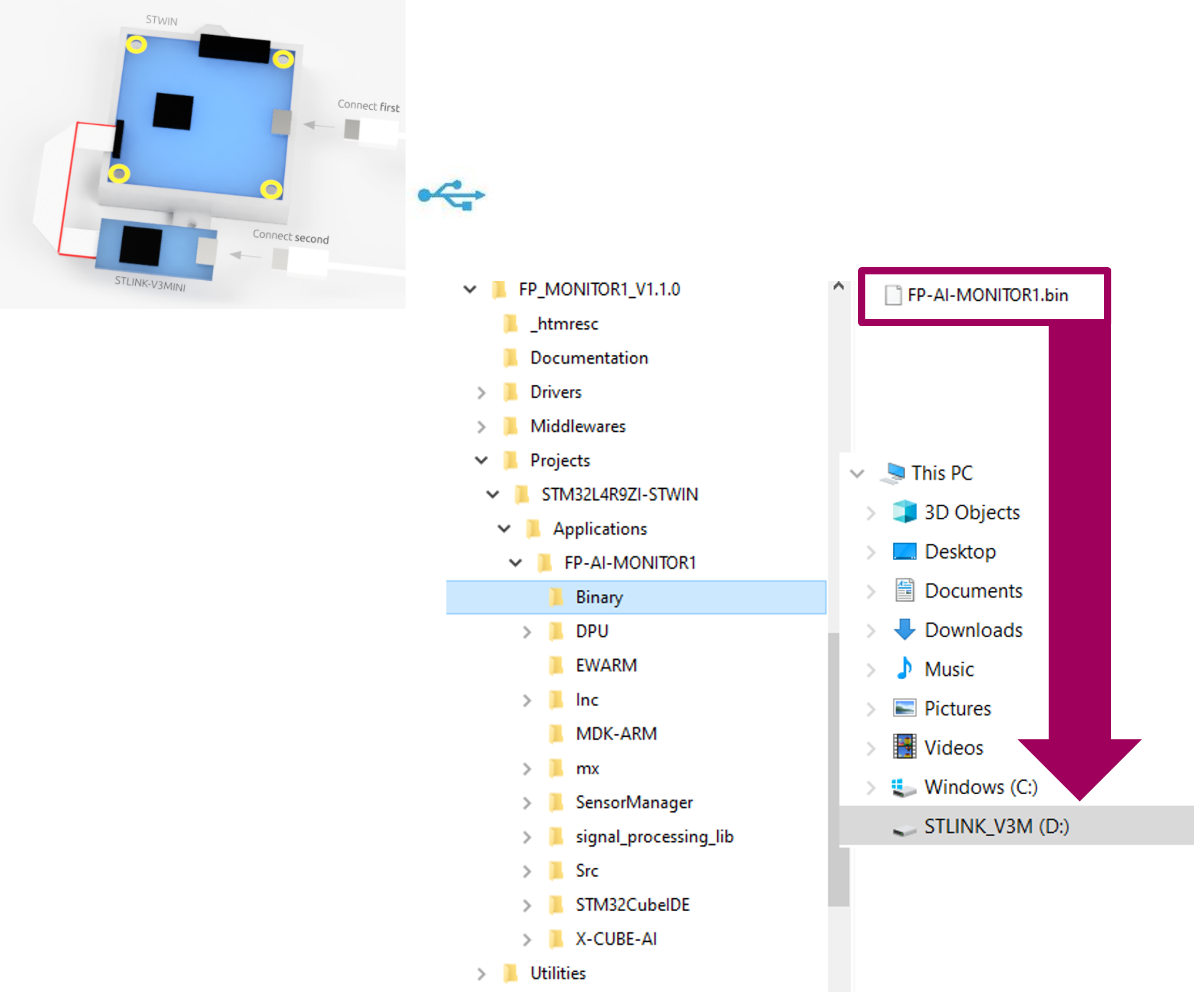
This section explains how to select binary firmware and program it into the STM32 microcontroller. Binary firmware is delivered as part of the FP-AI-MONITOR1 function pack. It is located in the FP-AI-MONITOR1_V1.0.0/Projects/STM32L4R9ZI-STWIN/Applications/FP-AI-MONITOR1/Binary/ folder. When the STM32 board and PC are connected through the USB cable on the STLINK-V3E connector, the related drive is available on the PC. Drag and drop the chosen firmware into that drive. Wait a few seconds for the firmware file to disappear from the file manager: this indicates that the firmware is programmed in the STM32 microcontroller.
2.4 Using the serial console
A serial console is used to interact with the host board (Virtual COM port over USB). With the Windows® operating system, the use of the Tera Term software is recommended. Following are the steps to configure the Tera Term console for CLI over a serial connection.
2.4.1 Set the serial terminal configuration
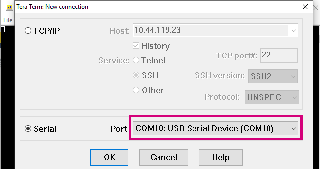
Start Tera Term, select the proper connection (featuring the STMicroelectronics name),
Set the parameters:
- Terminal
- [New line]:
- [Receive]: CR
- [Transmit]: CR
- [New line]:
- Serial
- The interactive console can be used with the default values.
2.4.2 Start FP-AI-MONITOR1 firmware
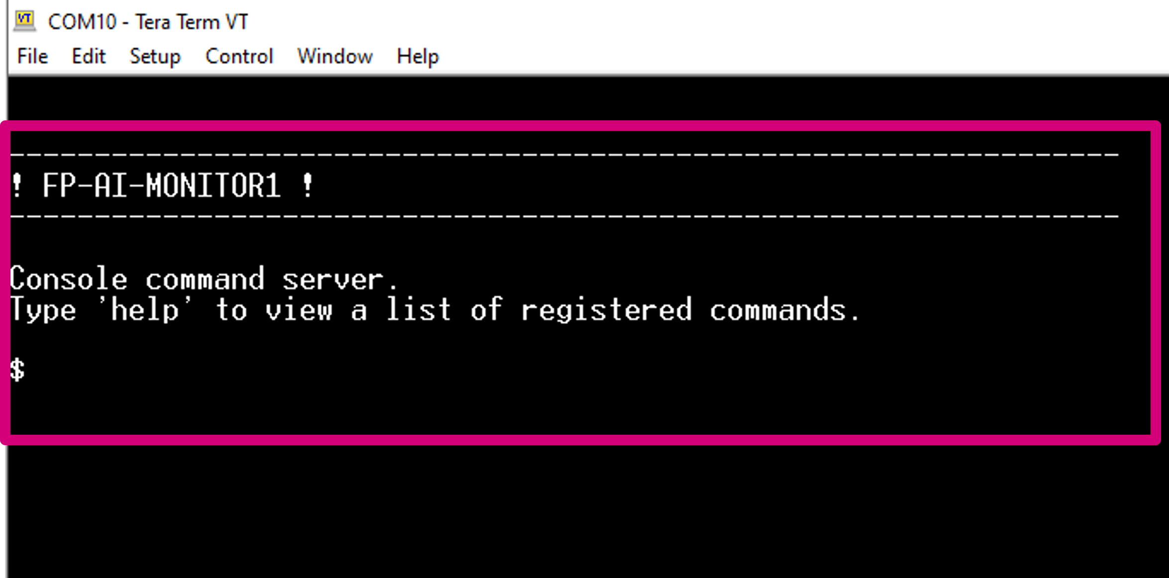
Restart the board by pressing the RESET button. The following welcome screen is displayed on the terminal.
From this point, start entering the commands directly or type help to get the list of available commands along with their usage guidelines.
Note: The firmware provided is generated with a HAR model based on SVC and users can test it straight out of the box. However for the NanoEdge™ AI Library a stub is provided in place of the library. The user must generate the library with the help of the NanoEdge™ AI Studio, replace the stub with this library, and rebuild the firmware. These steps will be described in detail in the article later.
3 Button-operated modes
This section provides details of the button operated mode for FP-AI-MONITOR1. The purpose of the extended mode is to enable the users to operate the FP-AI-MONITOR1 on STWIN even in the absence of the CLI console.
In button operated mode, the sensor node can be controlled through the user button instead of the interactive CLI console. The default values for node parameters and settings for the operations during auto-mode are provided in the FW. Based on these configurations, different modes such as ai, neai_detect, and neai_learn can be started and stopped through the user-button on the node.
3.1 Interaction with user
The button operated mode can work with or without the CLI and is fully compatible and consistent with the current definition of the serial console and its command line interface (CLI).
The supporting hardware for this version of the function-pack (STEVAL-STWINKT1B) is fitted with three buttons:
- User Button, the only button usable by the SW,
- Reset Button, connected to STM32 MCU reset pin,
- Power Button connected to power management,
and three LEDs:
- LED_1 (green), controlled by Software,
- LED_2 (orange), controlled by Software,
- LED_C (red), controlled by Hardware, indicates charging status when powered through a USB cable.
So, the basic user interaction for button-operated operations is to be done through two buttons (user and reset) and two LEDs (Green and Orange). Following provides details on how these resources are allocated to show the users what execution phases are active or to report the status of the sensor-node.
3.1.1 LED Allocation
In the function pack four execution phases exist:
- idle: the system waits for user input.
- ai detect: all data coming from the sensors are passed to the X-CUBE-AI library to detect anomalies.
- neai learn: all data coming from the sensors are passed to the NanoEdge™AI library to train the model.
- neai detect: all data coming from the sensors are passed to the NanoEdge™AI library to detect anomalies.
At any given time, the user needs to be aware of the current active execution phase. We also need to report on the outcome of the detection when the detect execution phase is active, telling the user if an anomaly has been detected, or what activity is being performed by the user using HAR application when "ai" context is running.
The onboard LEDs indicate the status of the current execution phase by showing which context is running and also by showing the output of the context (anomaly or one of the four activities in HAR case).
The green LED is used to show the user which execution context is being run.
| Pattern | Task |
|---|---|
| OFF | - |
| ON | IDLE |
| BLINK_SHORT | X-CUBE-AI Running |
| BLINK_NORMAL | NanoEdge™ AI learn |
| BLINK_LONG | NanoEdge™ AI detection |
The Orange LED is used to indicate the output of the running context as shown in the table below:
| Pattern | Reporting |
|---|---|
| OFF | Stationary if in X-CUBE-AI mode, Normal Behavior when in NEAI mode |
| ON | Biking |
| BLINK_SHORT | Jogging |
| BLINK_LONG | Walking |
Looking at these LED patterns the users is aware of the state of the sensor node even when CLI is not connected.
3.1.2 Button Allocation
In the extended autonomous mode, the user can trigger any of the four execution phases. The available modes are:
- idle: the system is waiting for a command.
- ai: run the X-CUBE-AI library and print the results of the live inference on the CLI (if CLI is available).
- neai_learn: all data coming from the sensor is passed to the NanoEdge™ AI library to train the model.
- neai_detect: all data coming from the sensor is passed to the NanoEdge™ AI library to detect anomalies.
To trigger these phases, the FP-AI-MONITOR1 is equipped with the support of the user button. In the STEVAL-STWINKT1B sensor-node, there are two software usable buttons:
- The user button: This button is fully programmable and is under the control of the application developer.
- The reset button: This button is used to reset the sensor-node and is connected to the hardware reset pin, thus is used to control the software reset. It resets the knowledge of the NanoEdge™ AI libraries and reset all the context variables and sensor configurations to the default values.
In order to control the executions phases, we need to define and detect at least three different button press modes of the user button.
Following are the types of the press available for the user button and their assignments to perform different operations:
| Button Press | Description | Action |
|---|---|---|
| SHORT_PRESS | The button is pressed for less than (200 ms) and released | Start AI inferences for X-CUBE-AI model. |
| LONG_PRESS | The button is pressed for more than (200 ms) and released | Starts the learning for NanoEdge™ AI Library. |
| DOUBLE_PRESS | A succession of two SHORT_PRESS in less than (500 ms) | Starts the inference for NanoEdge™ AI Library. |
| ANY_PRESS | The button is pressed and released (overlaps with the three other modes) | Stops the current running execution phase. |
4 Command line interface
The command-line interface (CLI) is a simple method for the user to control the application by sending command line inputs to be processed on the device.
4.1 Command execution model
The commands are grouped into three main sets:
- (CS1) Generic commands
- This command set allows the user to get the generic information from the device like the firmware version, UID, compilation date and time, and so on, and to start and stop an execution phase.
- (CS2) AI commands
- This command set contains commands which are AI specific. These commands enable users to work with the X-CUBE-AI and NanoEdge™ AI libraries.
- (CS3) Sensor configuration commands
- This command set allows the user to configure the supported sensors and to get the current configurations of these sensors.
4.2 Execution phases and execution context
The four system execution phases are:
- X-CUBE-AI: data coming from the sensors is passed through the X-CUBE-AI models to run the inference on the HAR classification..
- NanoEdge™ AI learning: data coming from the sensors is passed to the NanoEdge™ AI library to train the model.
- NanoEdge™ AI detection: data coming from the sensors is passed to the NanoEdge™ AI library to detect anomalies.
Each execution phase can be started and stopped with a user command start <execution phase> issued through the CLI.
An execution context, which is a set of parameters controlling execution, is associated with each execution phase. One single parameter can belong to more than one execution context.
The CLI provides commands to set and get execution context parameters. The execution context cannot be changed while an execution phase is active. If the user attempts to set a parameter belonging to any active execution context, the requested parameter is not modified.
4.3 Command summary
| Command name | Command string | Note |
|---|---|---|
| CS1 - Generic commands | ||
| help | help | Lists all registered commands with brief usage guidelines. Including the list of applicable parameters. |
| info | info | Shows firmware details and version. |
| uid | uid | Shows STM32 UID. |
| reset | reset | Resets the MCU system. |
| start | start <"ai", "neai_learn", or "neai_detect" > | Starts an execution phase according to its execution context, i.e. ai, neai_learn or neai_detect. |
| CS2 - AI specific commands | ||
| neai_init | neai_init | (Re)initializes the NanoEdge™ AI model by forgetting any learning. Used in the beginning and/or to create a new NanoEdge™ AI model. |
| neai_set | neai_set <param> <val> | Sets a PdM specific parameter in an execution context. |
| neai_get | neai_get <param> | Displays the value of the parameters in the execution context. The parameters are "sensitivity", "threshold", "signales", "timer", and "all". |
| ai_get | ai_get info | Displays the information about the embedded AI Model such as "weights", "MAACs", "RAM", "version of X-CUBE-AI" and so on. |
| CS3 - Sensor configuration commands | ||
| sensor_set | sensor_set <sensorID> <param> <val> | Sets the ‘value’ of a ‘parameter’ for a sensor with the sensor ID provided in ‘id’. The setable params are "FS", "ODR", and "enable". |
| sensor_get | sensor_get <sensorID>.<subsensorID> <param> | Gets the ‘value’ of a ‘parameter’ for a sensor with the sensor ID provided in ‘id’. The params are "FS", "ODR", "enable", "FS_List", "ODR_List", and "all". |
| sensor_info | sensor_info | Lists the type and ID of all supported sensors. |
5 Classification applications for sensing
5.1 Python Utilities for classification application
FP-AI-MONITOR1 comes equipped with two AI applications, a classification example for human activity recognition (HAR) based on X-CUBE-AI and an anomaly detection example based on NanoEdge™ AI. This section describes the HAR classification application.
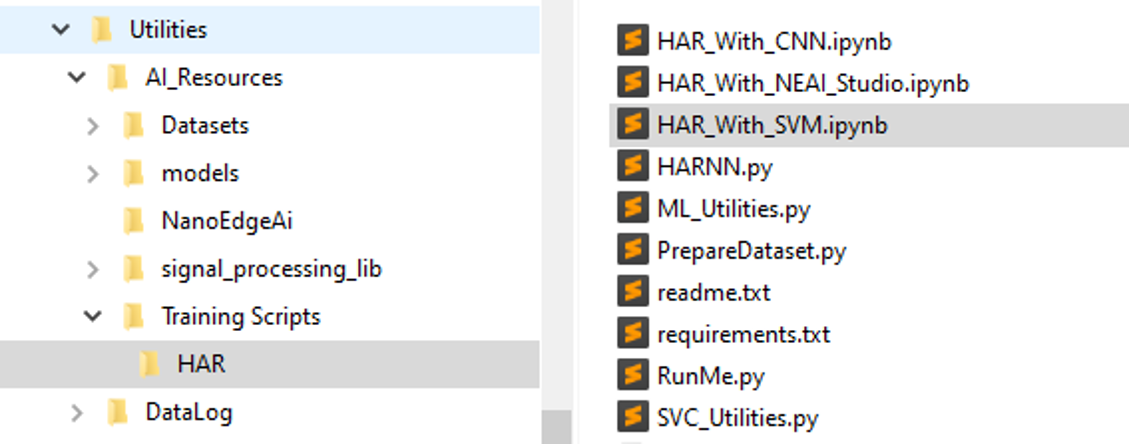
FP-AI-MONITOR1 comes with a Python utility code to generate the AI models for HAR both based on artificial neural networks and classical machine learning models using scikit-learn. These scripts are located under the FP-AI-MONITOR1_V1.0.0/Utilities/AI_Resources/Training Scripts/HAR/ directory. The following figure shows the contents of the utilities.
The utilities include two folder, AI_Resources (all the Python resources related to AI) and DataLog (binary and helper scripts for High Speed Datalogger). In the AI_Resources there are subdirectories of
- Dataset : Contains different datasets/holders for the datasets used in the function pack
- models : Contains the pregenerated and trained models for HAR along with their C-code
- NanoEdgeAi : Contains the helper scripts to prepare the data for the NanoEdge™ AI Studio from the HSDatalogs
- signal_processing_lib : Contains the code for various signal processing modules (there is equivalent embedded code available for all the modules in the function pack)
- Training Scripts : Contains the Python scripts for HAR examples using SVC, CNN, and NEAI.
The HAR subdirectory at the path FP-AI-MONITOR1_V1.0.0/Utilities/AI_Resources/Training Scripts/HAR/ contains three Jupyter notebooks:
- HAR_with_CNN.ipynb (a complete step-by-step code to build an HAR model based on Convolutional Neural Networks),
- HAR_with_SVC.ipynb (a complete step-by-step code to build an HAR model based on Support Vector Machine Classifier), and
- HAR_with_NEAI.ipynb (a complete step-by-step code to build NanoEdge™ AI Studio compliant files for all activities).
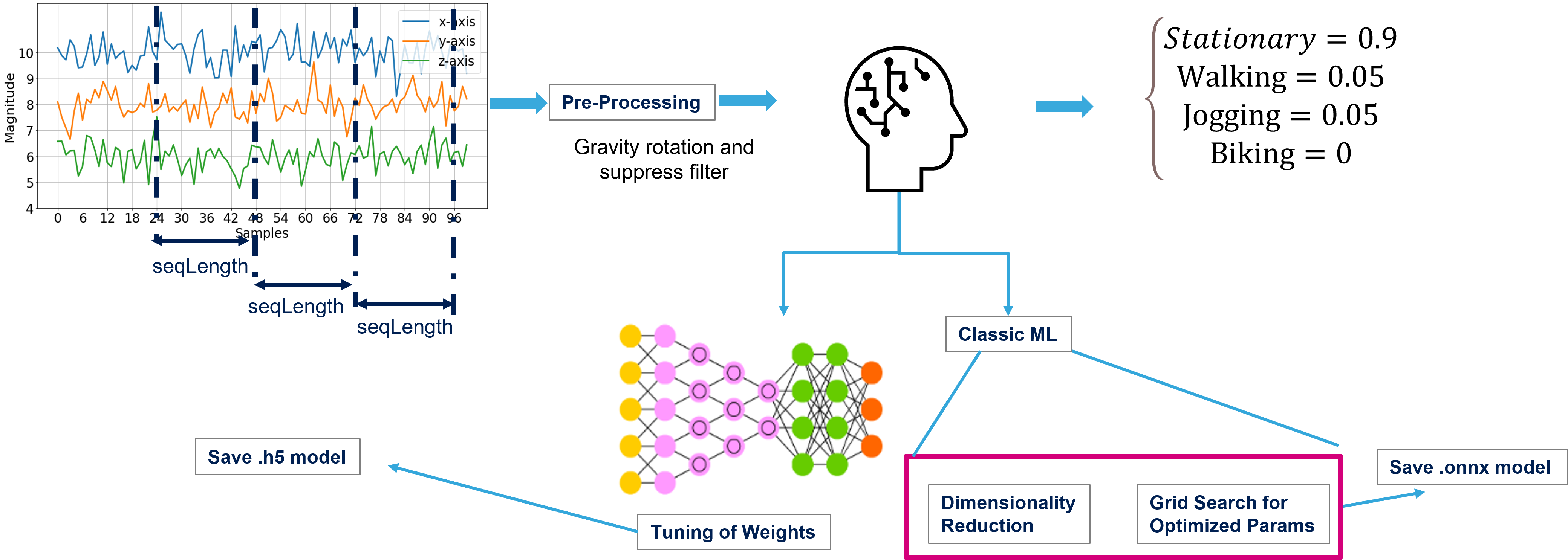
The FP-AI-MONITOR1 comes with a prebuilt model for HAR based on SVC for recognizing four activities, namely [Stationary, Walking, Jogging, Biking]. The following figure shows a complete flow of building an HAR application using CNN or SVC, generating the C-code using X-CUBE-AI and embedding it in the FP-AI-MONITOR1, installing it and then finally running the inference on the edge.
The Jupyter Notebooks in FP-AI-MONITOR1_V1.0.0/Utilities/AI_Resources/Training Scripts/HAR/ directory contain very detailed step-by-step processes to create SVC, CNN, and NEAI based HAR applications. This section describes briefly the steps to build this application in Python using the CNN and SVC scripts provided in this directory (yellow part). The steps are listed in the figure below:
The steps include:
- Segmenting the data into segments of length 24 (any segment length can be used depending on the requirements, but the length used in this case is the length based on a famous model architecture).
- Preprocess and condition the data, the gravity rotation is applied to the z-axis and suppression (any preprocessing chain can be applied depending on the users needs)
- a set of DSP feature extraction is provided in the subdirectory signal_processing_lib along with the equivalent embedded implementation.
- Model building and optimization (learning)
- In case of CNN, this step includes building a topology, and training of the weights.
- In case of SVC, this step includes finding the best hyper-parameters for the the model definition and performing the best dimension reduction to have smallest models providing the best performance.
- Validating the model using the unseen/test data.
- Exporting the trained model as .h5 (in case of CNN) or .onnx (in case of SVC).
The next section shows how to take these pretrained models and convert them into optimized C-code using X-CUBE-AI. The code can then be embedded and installed into the sensor-board to run the inferences on the edge.
5.2 Generating C-code for the AI model using STM32 X-CUBE-AI
This section explains how to generate the code for a pretrained AI model using STM32 X-CUBE-AI. For this purpose the code is generated using the .h5 model provided. The readers can generate C-code for any .h5 or .onnx model using this method.
Following list gives a step-by-step guide for generating the C-code for the h5 model.
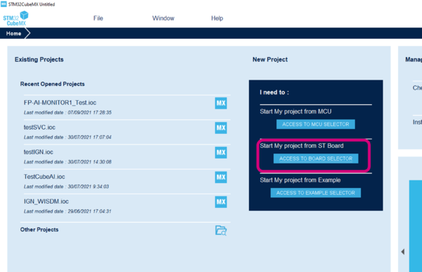
Step1 : Open the STM32CubeMX and click on the ACCESS TO BOARD SELECTOR button as shown in the image below.
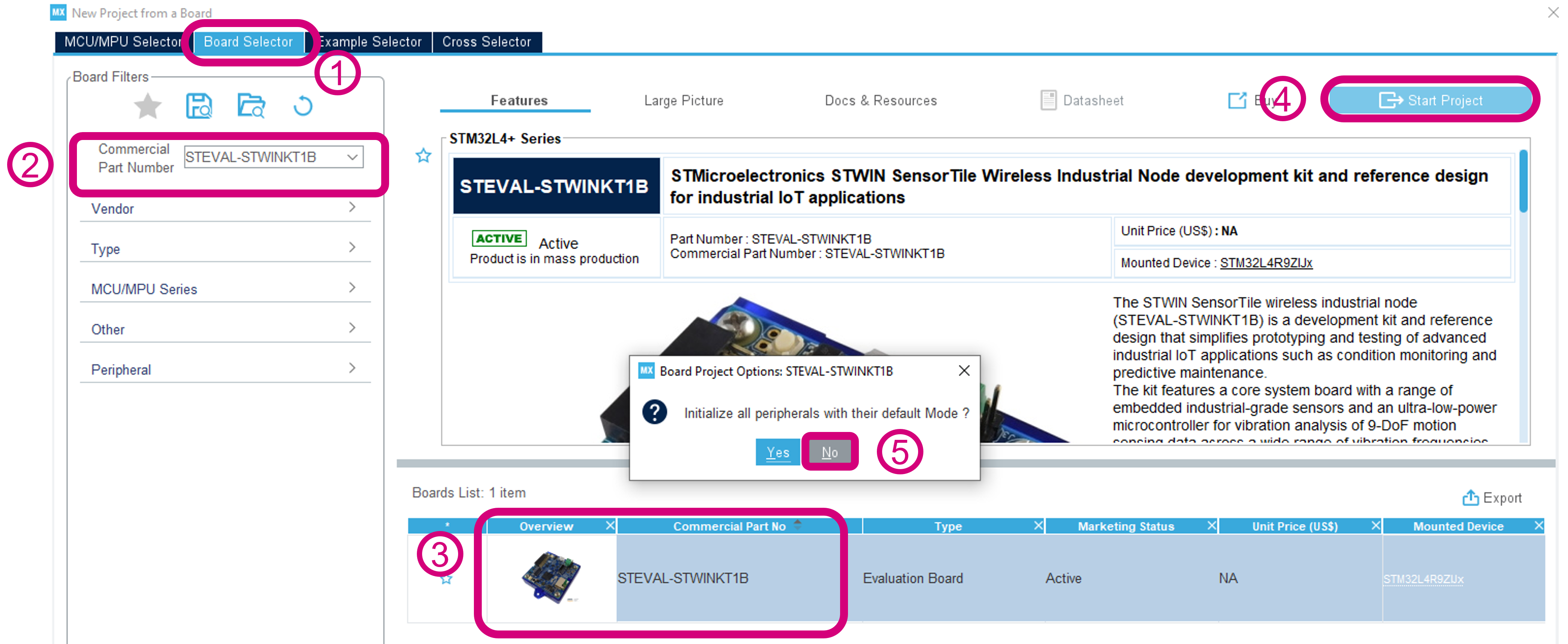
Step2 : Create a new project for STEVAL-STWINKT1B:
- Confirm the board selector tab is selected,
- Search for the right board, and in our case it is the
STEVAL-STWINKT1B, by typing the name in the search bar, - Select the board by clicking on either the board image or the name of the board,
- Start Project, and
- Chose
NOfor the Peripheral initialization option as this is not required for our purpose.
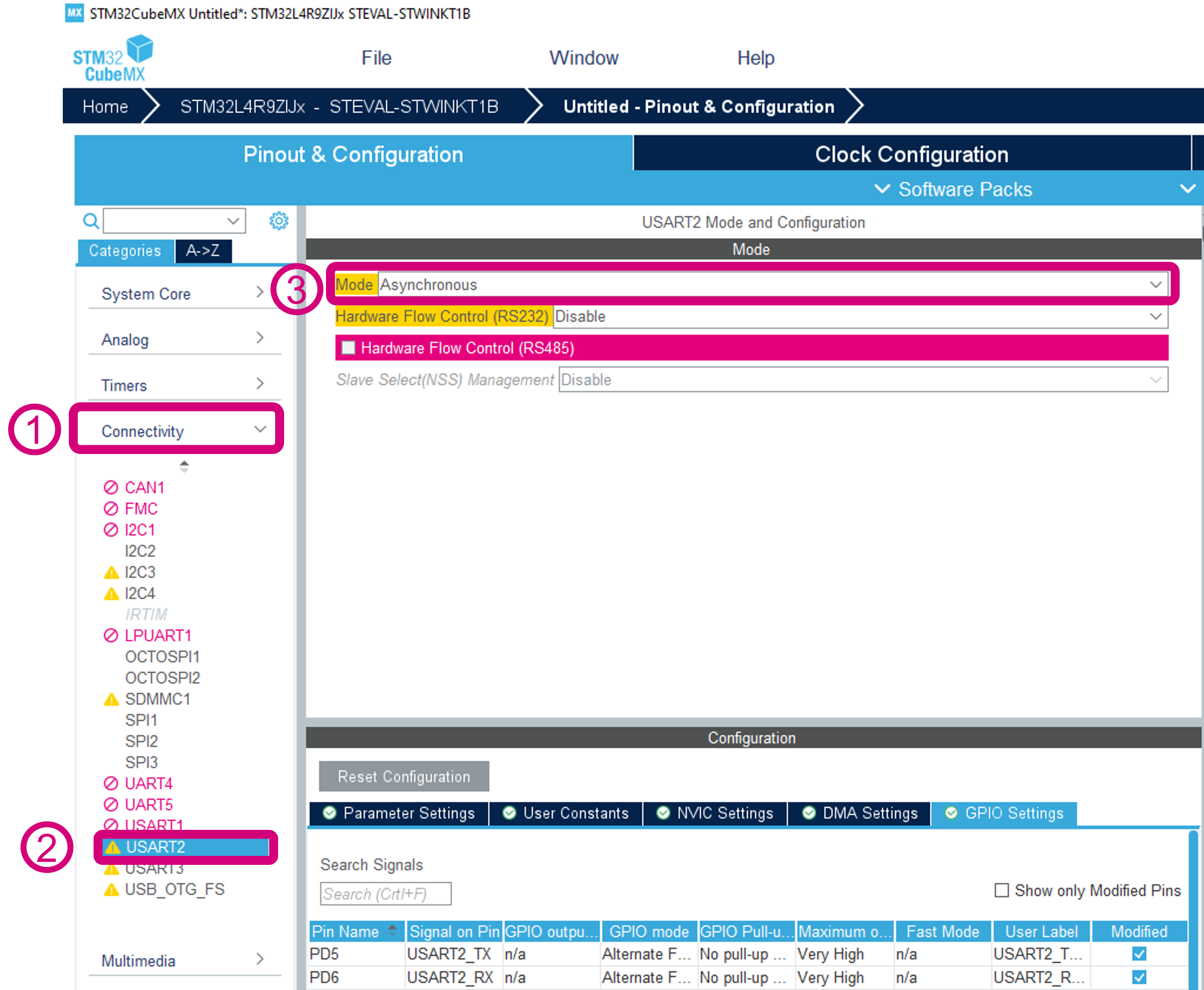
Step3 : Configuring connectivity
- Click on the connectivity option in the left menu
- Select USART2
- Enable the "Asynchronous mode" by selecting it in the drop-down menu.
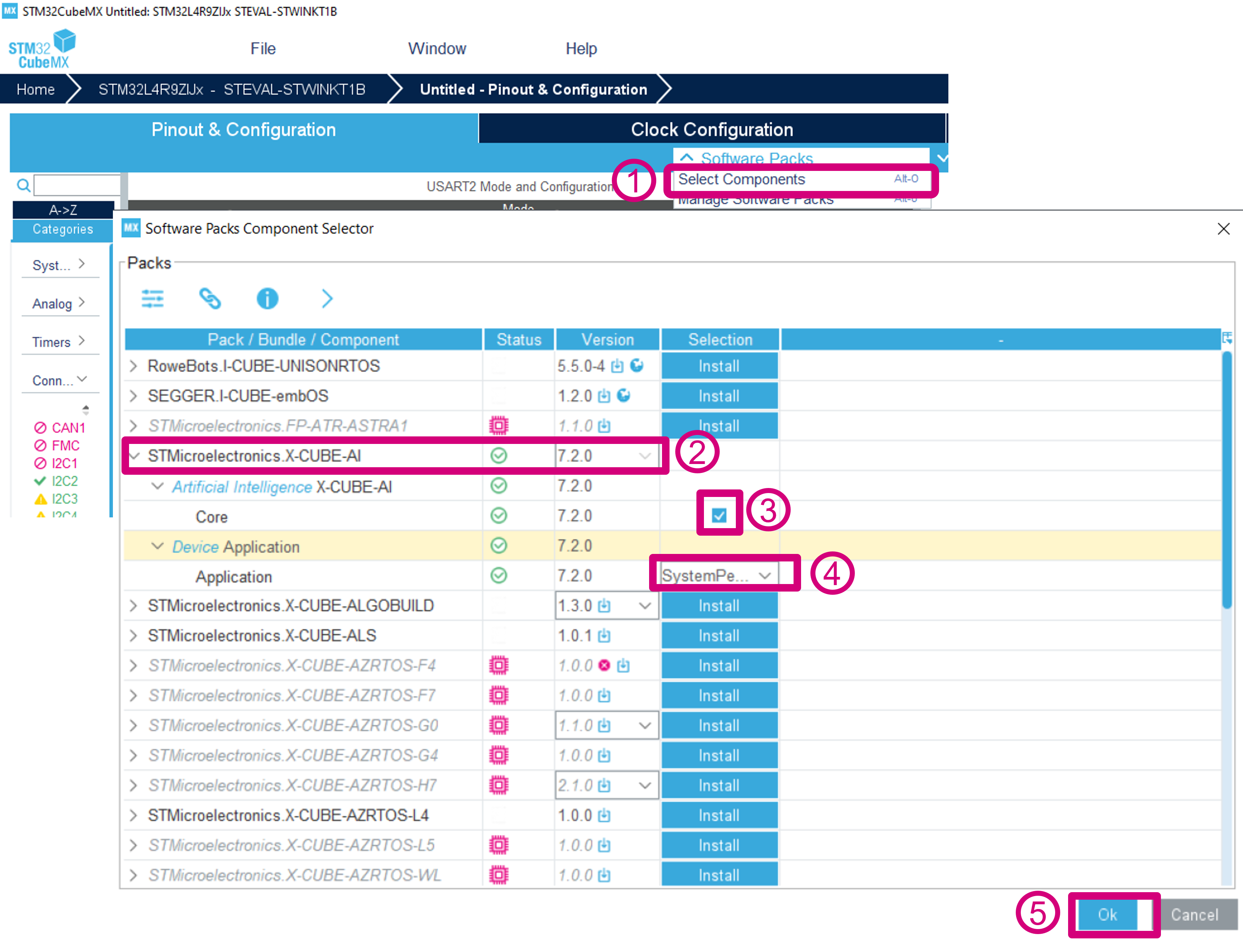
Step4 : Add the X-CUBE-AI in the software packs for the project
- Click on the
Software Packs, and select theSelect Componentsoption - Click on the
STMicroelectronics X-CUBE-AI. UseVersion 7.0.0as preference but any version from 7.0 or later can be used, - Click on checkbox in front of
Coreto add the X-CUBE-AI code in the software stack. - Expand the
Device Applicationmenu and from the dropdown menu under selection column selectSystemPerformance. - Click
OKbutton to finish the addition of the X-CUBE-AI in the project.
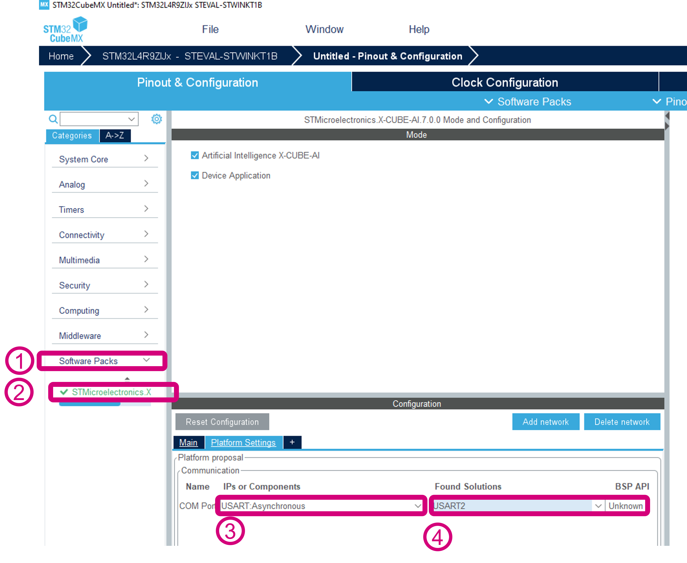
Step 5 : Platform Settings
- Click on
Software Packs, - Choose STMicroelectronics.X-CUBE-AI,
- Select
USART:Asynchronousoption for the COM Port, - Select USART2 in "Found Solutions" drop-down.
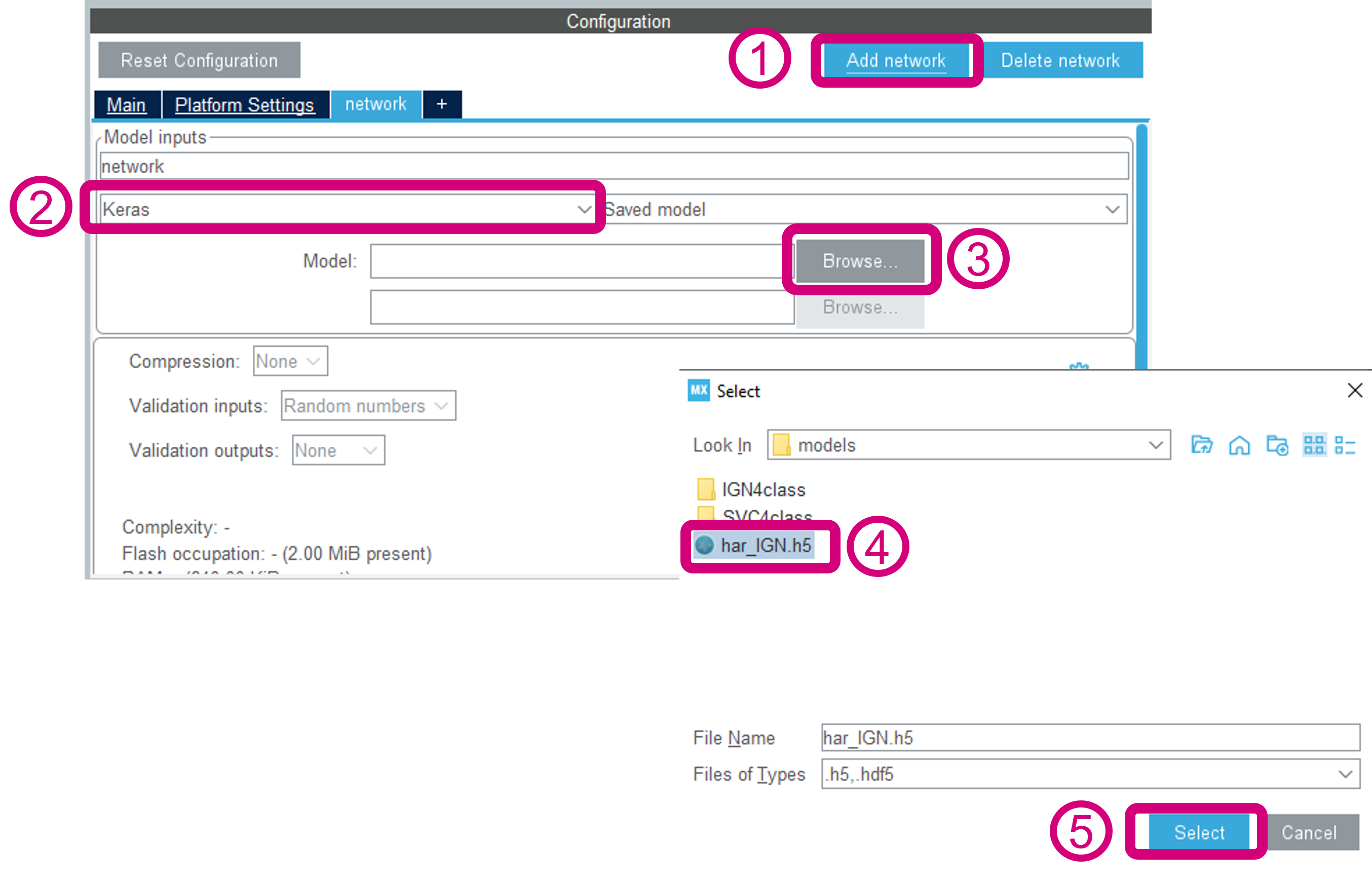
Step6 : Adding network for code generation
- Click on the add network button,
- From drop down select the type of the network. For the applications in this function pack these can be
KerasorONNX - Click on the
Browsebutton to select the model. - The example in the figure below shows the
har_IGN.h5being used, which is located underFP-AI-MONITOR1_V1.0.0/Utilities/AI_Resources/models. Select the model and click OK.
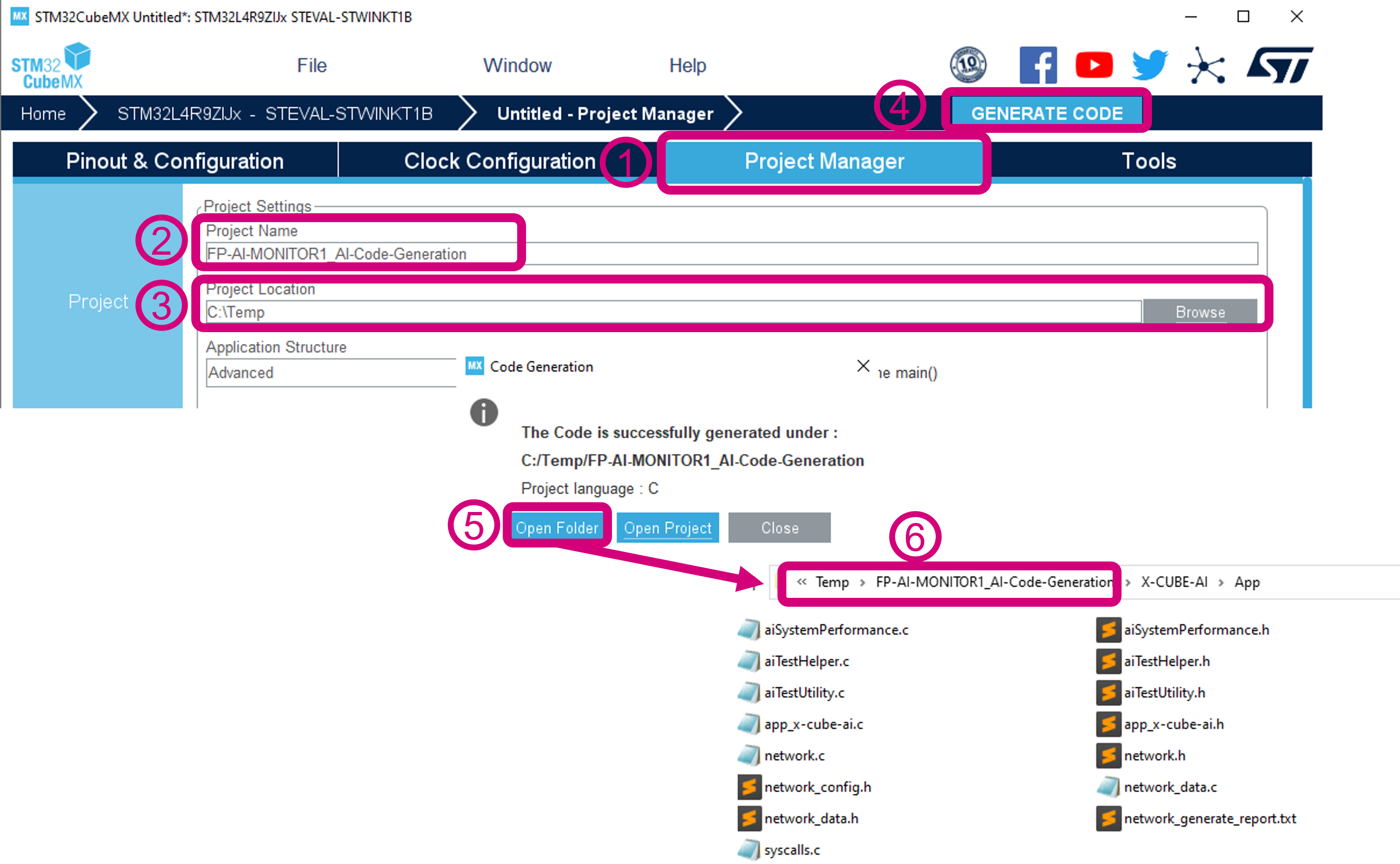
<dev/> Step7 : Generating the C-code
- Go to
Project Manager - Assign a "Project Name", in the figure below it is
FP-AI-MONITOR1_AI-Code-Generation - Choose a Project Location, in the figure below it is C:/Temp/
- Click on the GENERATE CODE button. A progress bar will start and shows progress across the different code generation steps.
- Upon completion of the code generation process the user will see a dialog as in the figure below. This shows completion of the code generation. Click on the Open Folder button to open the project with the generated code.
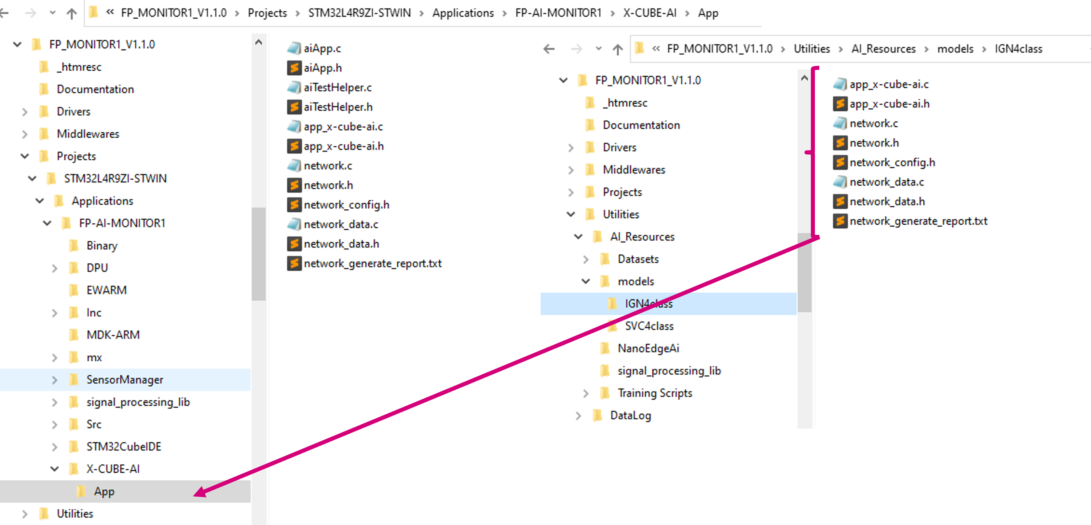
- The files present for the network model that have to be replaced in the provided project are located in the following directory:
FP-AI-MONITOR1_AI-Code-Generation_X-CUBE-AI/App/as shown in the figure below.
The next section shows how these files are used to replace the existing model embedded in the FP-AI-MONITOR1 software step-by-step and install it on the sensor-board.
5.3 Replacing the prebuilt classification AI model with generated one
The prebuilt model provided in the CLI example binary is based on the Support Vector Classifier (SVC). The Python script along with detailed instructions on how to prepare the dataset, build the model, and convert it to onnx is provided in the Jupyter Notebook available in /FP-AI-MONITOR1_V1.0.0/Utilities/AI_Resources/Training Scripts/HAR/HAR_With_SVC.ipynb. The building of these models and C-code generation is out of the scope of this article and readers are invited to refer to the user-manual for the detailed instructions. This article describes how a user replaces the default model provided in the function pack by a custom generated model once the C-code using STM32CubeMX extension X-CUBE-AI is generated. In this example the provided SVC model is replaced with the prebuilt and converted CNN model provided in the /FP-AI-MONITOR1_V1.0.0/Utilities/AI_Resources/models/IGN4class/ folder. The details on the data used for training and the topology are located in the training scripts provided under /FP-AI-MONITOR1_V1.0.0/Utilities/AI_Resources/Training Scripts/HAR/HAR_With_CNN.ipynb.
To update the model, the user must copy and replace following files in the /FP-AI-MONITOR1_V1.0.0/Projects/STM32L4R9ZI-STWIN/Applications/FP-AI-MONITOR1/X-CUBE-AI/App/ folder as shown in the figure above:
- app_x-cube-ai.c,
- app_x-cube-ai.h,
- network.c,
- network.h,
- network_config.h,
- netowrk_data.h,
- network_generate_report.h.
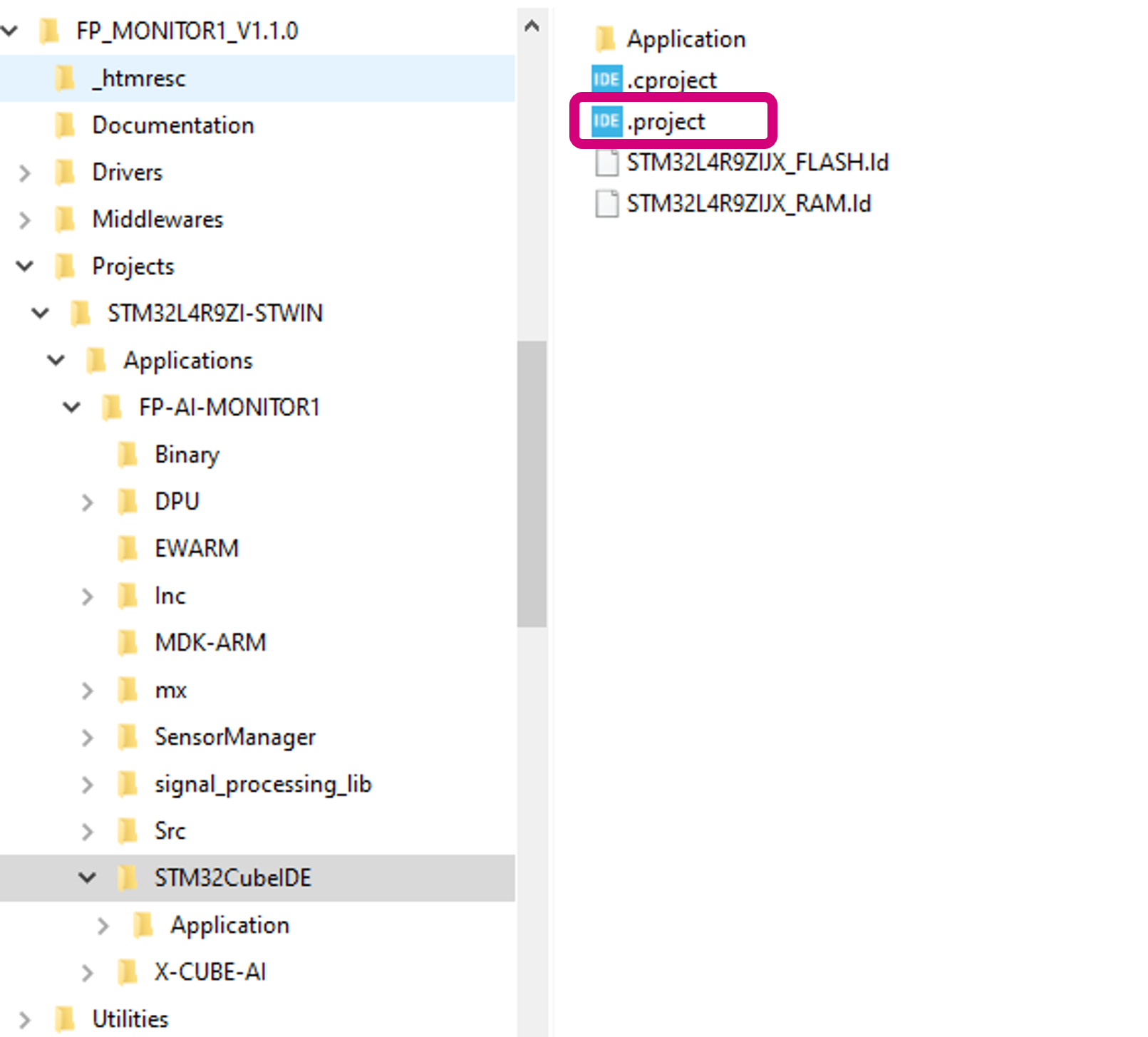
Once the files are copied, the user must open the project with the CubeIDE. To do so, go to the /FP-AI-MONITOR1_V1.0.0/Projects/STWINL4R9ZI-STWIN/Applications/FP-AI-MONITOR1/STM32CubeIDE/ folder and double click .project file as shown in the figure below.
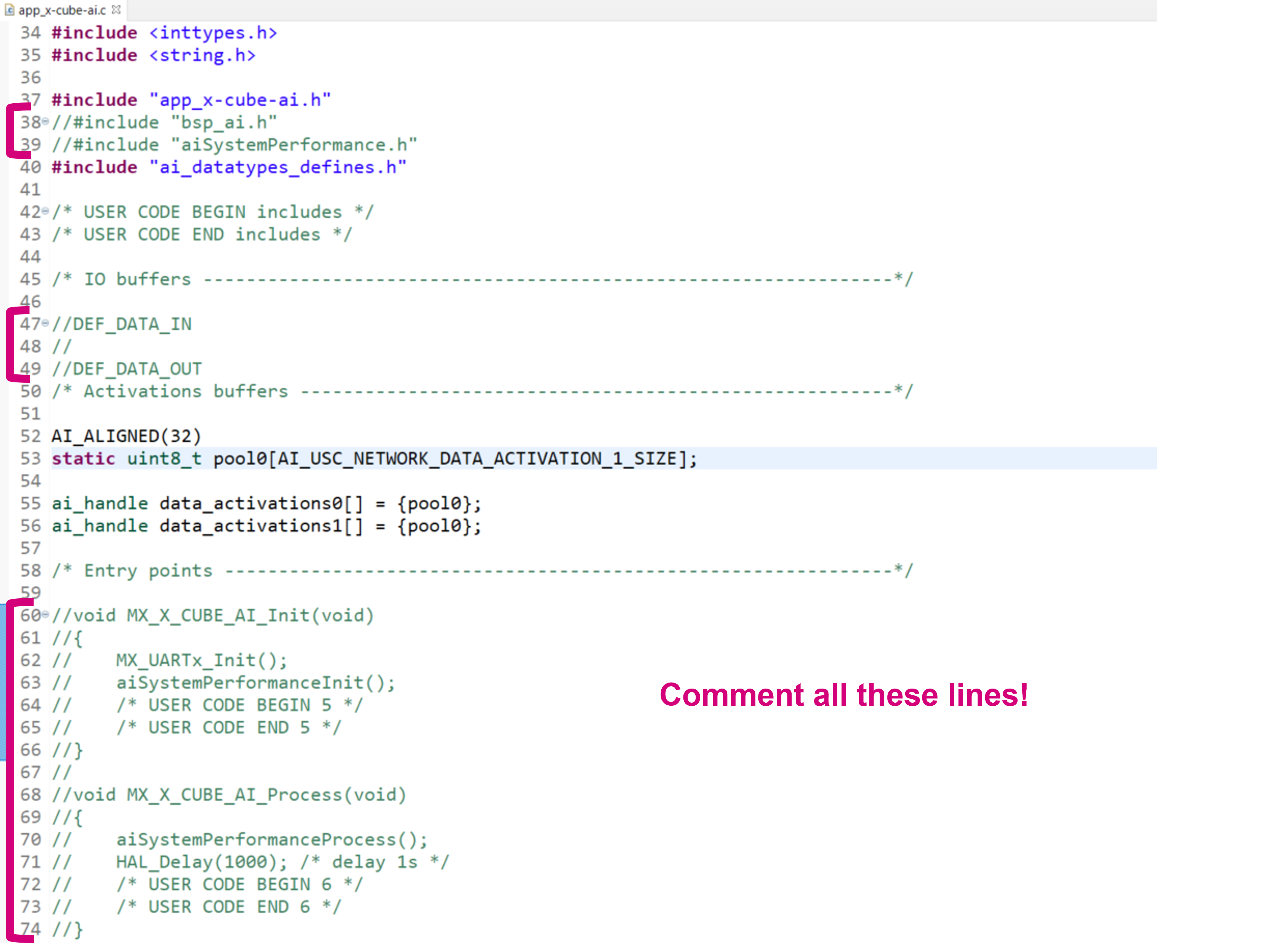
Once the project is opened, go to FP-AI-MONITOR1_V1.0.0/Projects/STM32L4R9ZI-STWIN/Application/FP-AI-MONITOR1/X-CUBE-AI/App/app_x-cube-ai.c file and comment the following lines of the code as shown in the figure below.
5.3.1 Building and installing the project
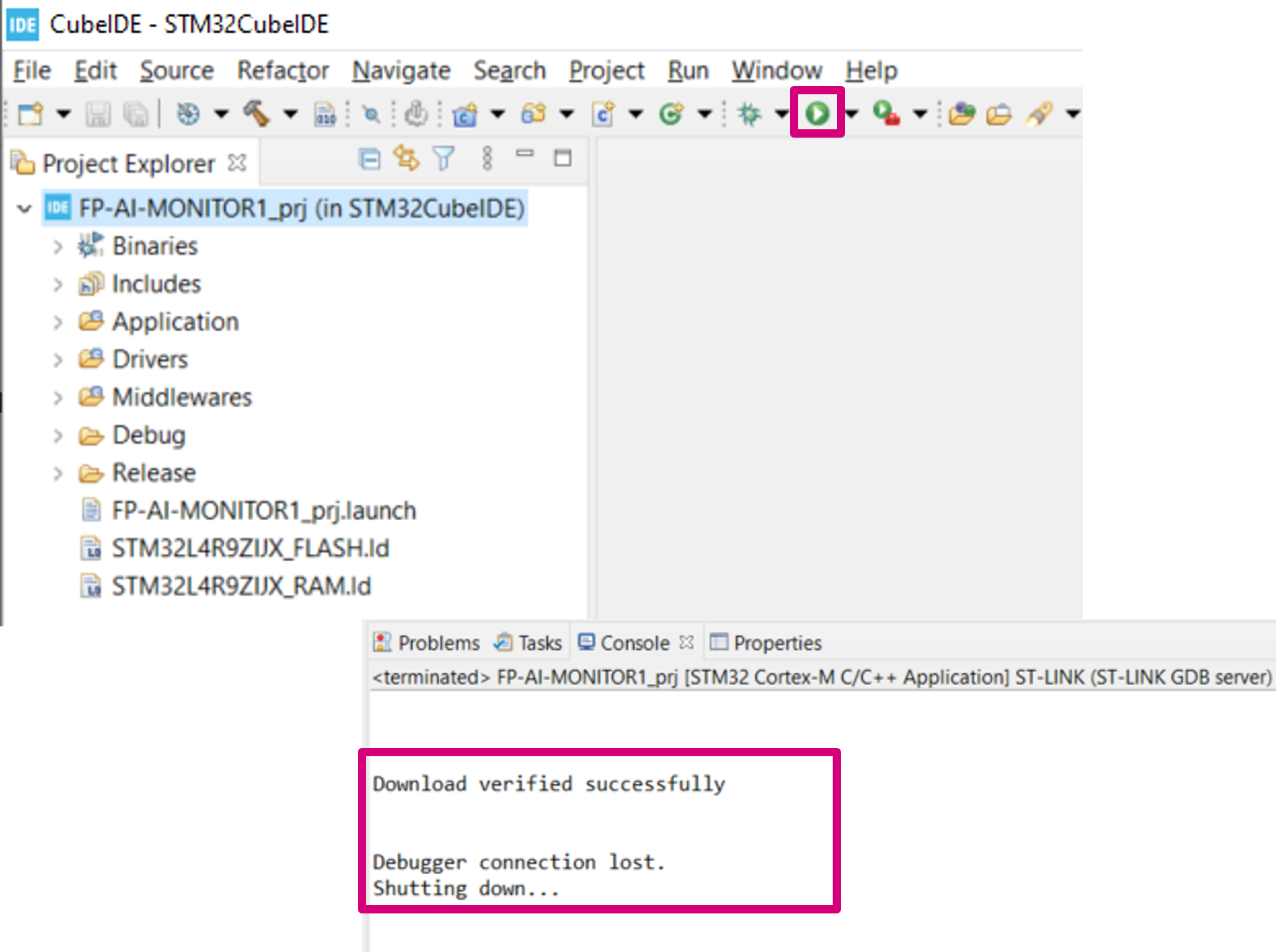
Then build and install the project in STWIN sensor-board by pressing the play button as shown in the figure below.
A message saying Download verified successfully indicates the new firmware is programmed in the sensor-board.
5.4 Running the AI application
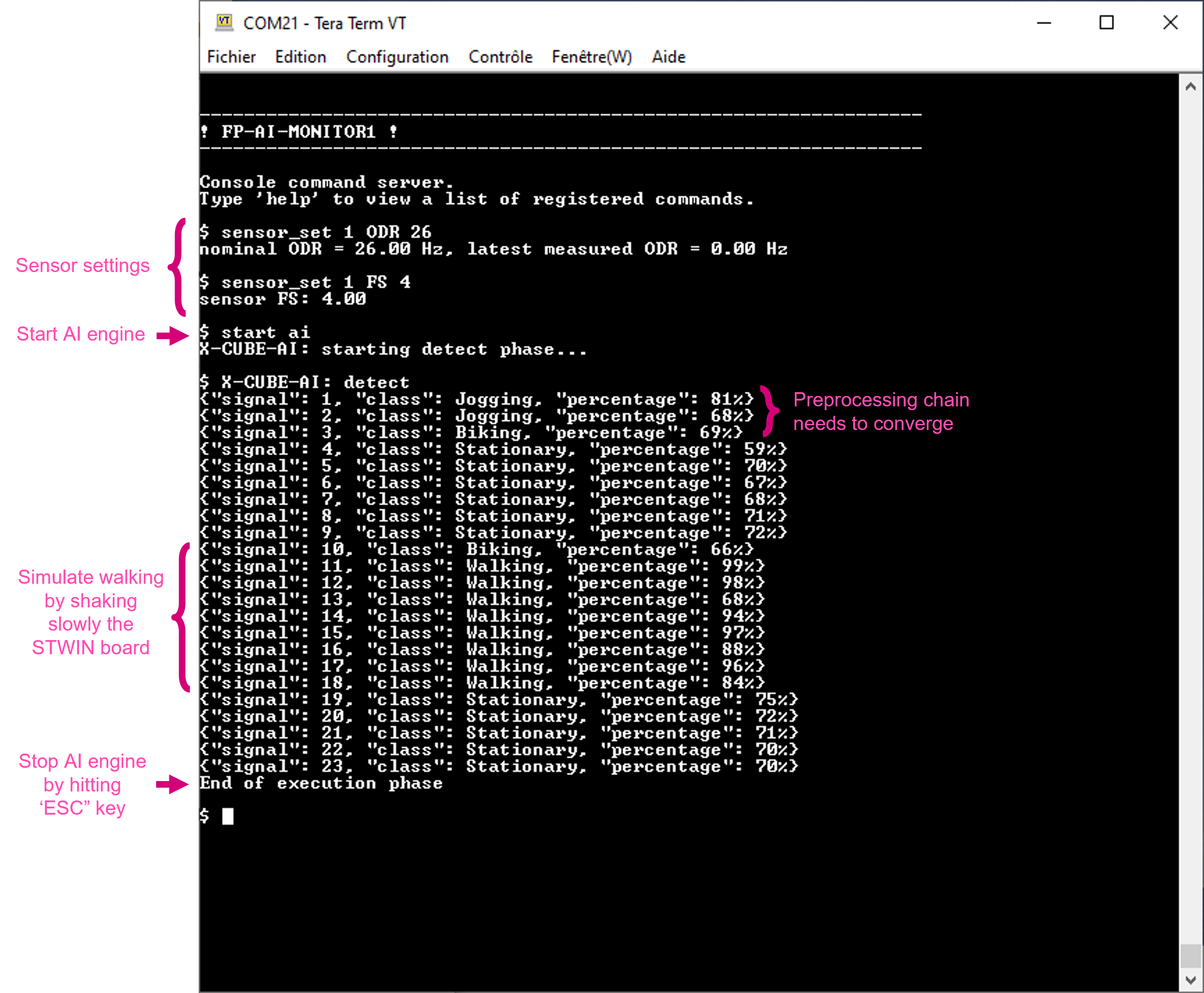
The CLI application comes with a prebuilt Human Activity Recognition model. This functionality is started by typing the command:
$ start ai
Note that the provided HAR model is built with a dataset created using the IHM330DHCX_ACC sensor with ODR = 26, and FS = 4. To achieve a best performance, the user must set these parameters to the sensor configuration using the sensor_set command as provided in the Command Summary table.
Running the $ start ai command starts doing the inference on the accelerometer data and predict the performed activity along with the confidence. The supported activities are:
- Stationary,
- Walking,
- Jogging, and
- Biking.
The following figure is a screen shot of the normal working session of the AI command in CLI application.
6 Condition monitoring using NanoEdge™ AI Machine Learning library
This section provides a complete anomaly detection method using the NanoEdge™ AI library. FP-AI-MONITOR1 includes a pre-integrated stub which is easily replaced by an AI condition monitoring library generated and provided by NanoEdge™ AI Studio. This stub simulates the NanoEdge™ AI related functionalities, such as running learning and detection phases on the edge.
The learning phase is started by issuing a command $ start neai_learn from the CLI console. Launching this command starts the process of learning and displays a message on the console every time learning is performed on a new signal (see the snippet below):
$ CTRL: ! This is a stubbed version, please install NanoEdge AI library !
NanoEdge AI: learn
{"signal": 1, "status": success}
{"signal": 2, "status": success}
{"signal": 3, "status": success}
:
:
:
End of execution phase
The process is stopped by pressing the ESC key on the keyboard.
The learning is also started by performing a long-press of the user button. Pressing the user button again stops the learning process.
Once the normal conditions are learned, the user starts the condition monitoring process by issuing the command $ start neai_detect command. This command starts the inference phase and checks the similarity of the presented signal with the learned normal signals. If the similarity is less than the set threshold default: 90%, the similarity value is printed showing the occurrence of an anomaly. This behavior is shown in the snippet below:
$ start neai_detect
NanoEdge AI: starting detect phase...

$ CTRL: ! This is a stubbed version, please install NanoEdge AI library !
NanoEdge AI: detect
{"signal": 1, "similarity": 0, "status": anomaly}
{"signal": 2, "similarity": 1, "status": anomaly}
{"signal": 3, "similarity": 2, "status": anomaly}
:
:
{"signal": 90, "similarity": 89, "status": anomaly}
{"signal": 91, "similarity": 90, "status": anomaly}
{"signal": 102, "similarity": 0, "status": anomaly}
{"signal": 103, "similarity": 1, "status": anomaly}
{"signal": 104, "similarity": 2, "status": anomaly}
End of execution phase
or by double-pressing the user button on the sensor board.
The process is stopped by pressing the ESC key on the keyboard or alternatively pressing the user button .
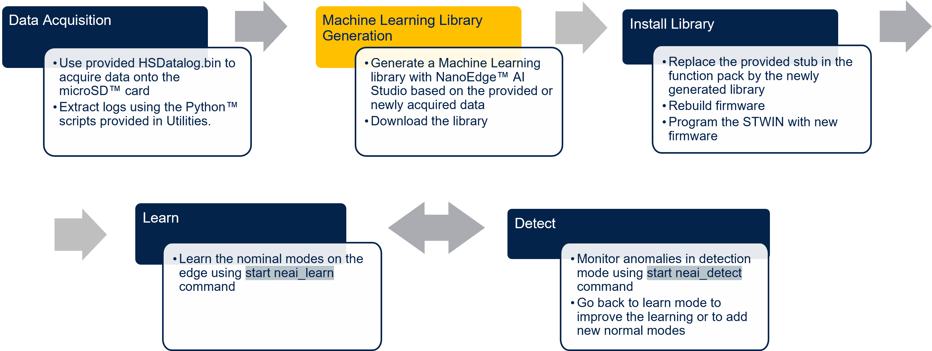
The following section shows how to generate a NanoEdge™ AI library for anomaly detection using NanoEdge™ AI Studio and FP-AI-MONITOR1, and how to set up an application for condition monitoring. The steps are provided with brief details in the following figure.
6.1 Generating a condition monitoring library
This section provides a step-by-step guide on how to generate, and install NanoEdge™ AI libraries by linking them to the provided project in FP-AI-MONITOR1 and then use them to perform the condition monitoring on the edge, by running first learning and then detection mode.
6.1.1 Data logging for normal and abnormal conditions
The details on how to acquire the data are provided in the section Datalogging using HSDatalog.
6.1.2 Data preparation for library generation with NanoEdge™ AI Studio
The data logged through the datalogger is in the binary format and is not user readable nor compliant with the NanoEdge™ AI Studio format as it is. To convert this data to a useful form, FP-AI-MONITOR1 provides Python™ utility scripts on the path /FP-AI-MONITOR1_V1.0.0/Utilities/AI-resources/NanoEdgeAi/.
The Jupyter Notebook NanoEdgeAI_Utilities.ipynb provides a complete example of data preparation for a three speed fan library generation running in normal and clogged condition. In addition there is a HSD_2_NEAISegments.py is provided if user wants to prepare segments for a given data acquisition. This script is used by issuing the following command for a data acquisition with ISM330DHCX_ACC sensor.
python HSD_2_NEAISegments.py ../Datasets/Fan12CM/ISM330DHCX/normal/1000RPM/
This command will generate a file named as ISM330DHCX_Cartesiam_segments_0.csv using the default parameter set. The file is generated with segments of length 1024 and stride 1024 plus the first 512 samples are skipped from the file.
6.1.3 Library generation using NanoEdge™ AI Studio
Running the scripts in Jupyter Notebook will generate the normal_WL1024_segments.csv and clogged_WL1024_segments.csv files. In this section it is described how to generate the libraries using these normal and abnormal segment files.
The process of generating the libraries with NanoEdge™ AI Studio consists of six steps. These steps are shown in the figure below.
- Hardware description
- Choosing the target platform or a microcontroller type: STEVAL-STWINKT1B Cortex-M4
- Maximum amount of RAM to be allocated for the library: Usually a few Kbytes is enough (but it depends on the data frame length used in the process of data preparation, 32 Kbytes is a good starting point).
- Sensor type : 3-axis accelerometer
- Providing the sample contextual data for normal segments to adjust and gauge the performance of the chosen model (
normal_WL1024_segments.csv) - Providing the sample contextual data for abnormal segments to adjust and gauge the performance of the chosen model (
clogged_WL1024_segments.csv). - Benchmarking of available models and choose the one that complies with the requirements.
- Validating the model for learning and testing through the provided emulator which emulates the behavior of the library on the edge.
- The final step is to compile and download the libraries. In this process, the flag
"-mfloat-abi"has to becheckedfor using libraries with hardware FPU. All the other flags can be left to the default state.- Note for using the library with μKeil also check -fshort-wchar in addition to -mfloat-abi.
Detailed documentation on the NanoEdge™ AI Studio.
.6.2 Installing the NanoEdge™ Machine Learning library
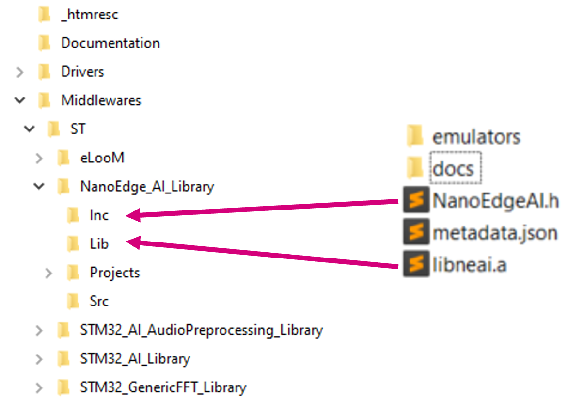
Once the libraries are generated and downloaded from NanoEdge™ AI Studio, the next step is to link these libraries to FP-AI-MONITOR1 and run them on the STWIN. The FP-AI-MONITOR1, comes with the library stubs in the place of the actual libraries generated by NanoEdge™ AI Studio. This is done to simplify the linking of the generated libraries. In order to link the actual libraries, the user needs to copy the generated libraries and replace the existing stub/dummy libraries and header files NanoEdgeAI.h, and libneai.a files present in the folders Inc, and lib, respectively. The relative paths of these folders are /FP_AI_MONITOR1_V1.0.0/Middlewares/ST/NanoEdge_AI_Library/ as shown in the figure below.
Once these files are copied, the project must be reconstructed and programmed on the sensor board to link the libraries correctly. For this, the user must open the project in STM32CubeIDE located in the /FP-AI-MONITOR1_V1.0.0/Projects/STWINL4R9ZI-STWIN/Applications/FP-AI-MONITOR1/STM32CubeIDE/ folder and double click .project file as shown in the figure below.
To build and install the project click on the play button and wait for the successful download message as shown in the section Build and Install Project.
Once the sensor-board is successfully programmed, the welcome message appears in the CLI (Tera Term terminal). If the message does not appear try to reset the board by pressing the RESET button.
6.3 Testing the NanoEdge™ AI Machine Learning library
Once the STWIN is programmed with the FW containing a valid library, the condition monitoring libraries are ready to be tested on the sensor board. The learning and detection commands can be issued and now the user will not see the warning of the stub presence.
To achieve the best performance, the user must perform the learning using the same sensor configurations which were used during the contextual data acquisition.
6.4 Additional parameters in condition monitoring
For user convenience, the CLI application also provides handy options to easily fine-tune the inference and learning processes. The list of all the configurable variables is available by issuing the following command:
$ neai_get all
NanoEdgeAI: signals = 0
NanoEdgeAI: sensitivity = 1.000000
NanoEdgeAI: threshold = 95
NanoEdgeAI: timer = 0
Each of the these parameters is configurable using the neai_set <param> <val> command.
This section provides information on how to use these parameters to control the learning and detection phase. By setting the "signals" and "timer" parameters, the user can control how many signals or for how long the learning and detection is performed (if both parameters are set the learning or detection phase stops whenever the first condition is met). For example, to learn 10 signals, the user issues this command, before starting the learning phase as shown below.
$ neai_set signals 10
NanoEdge AI: signals set to 10
$ start neai_learn
NanoEdgeAI: starting
$ {"signal": 1, "status": success}
{"signal": 2, "status": success}
{"signal": 3, "status": success}
:
:
{"signal": 10, "status": success}
NanoEdge AI: stopped
If both of these parameters are set to "0" (default value), the learning and detection phases will run indefinitely.
The threshold parameter is used to report any anomalies. For any signal which has similarities below the threshold value, an anomaly is reported. The default threshold value used in the CLI application is 90. Users can change this value by using neai_set threshold <val> command.
Finally, the sensitivity parameter is used as an emphasis parameter. The default value is set to 1. Increasing this sensitivity will mean that the signal matching is to be performed more strictly, reducing it will relax the similarity calculation process, i.e. resulting in higher matching values.
For further details on how NanoEdge™ AI libraries work users are invited to read the detailed documentation of NanoEdge™ AI Studio.
7 Data collection
The data collection functionality is out of the scope of this function pack. However, to simplify the task of the users and to allow them the possibility to perform a datalog, the precompiled HSDatalog.bin file for FP-SNS-DATALOG1 is provided in the Utilities which is located under path /FP-AI-MONITOR1_V1.0.0/Utilities/Datalog/. To acquire the data from any of the available sensors on the sensor-board the user programs the sensor-board with this binary using the drag-drop method shown in section 2.3.
Once the sensor-board is programmed log the data using the following instructions.
- Place a
DeviceConfig.jsonfile with the sensors configurations to be used for the datalogging in the root folder of the microSDTM card. Some sample.jsonfiles are provided in the package and are located inFP-AI-MONITOR1_V1.0.0/Utilities/Datalog/Sample_STWIN_Config_Files/. These files are to be precisely namedDeviceConfig.json. - Insert the SD card into the STWIN board.
- Reset the board. Orange LED blinks once per second. The custom sensor configurations provided in
DeviceConfig.jsonare loaded from the file. - Press the [USR] button to start data acquisition on the SD card. The orange LED turns off and the green LED starts blinking to signal sensor data is being written into the SD card.
- Press the [USR] button again to stop data acquisition. Do not unplug the SD card or turn the board off before stopping the acquisition otherwise the data on the SD card will be corrupted.
- Remove the SD card and insert it into an appropriate SD card slot on the PC. The log files are stored in
STWIN_###folders for every acquisition, where###is a sequential number determined by the application to ensure log file names are unique. Each folder contains a file for each active sub-sensor calledSensorName_subSensorName.datcontaining raw sensor data coupled with timestamps, aDeviceConfig.jsonwith specific information about the device configuration, necessary for correct data interpretation, and anAcquisitionInfo.jsonwith information about the acquisition.
- FP-AI-MONITOR1: Multi-sensor AI data monitoring framework on wireless industrial node, function pack for STM32Cube
- User Manual : User Manual for FP-AI-MONITOR1
- STEVAL-STWINKT1B
- STM32CubeMX : STM32Cube initialization code generator
- X-CUBE-AI : expansion pack for STM32CubeMX
- NanoEdge™ AI Studio: NanoEdge™ AI the first Machine Learning Software, specifically developed to entirely run on microcontrollers.
- DB4345: Data brief for STEVAL-STWINKT1B.
- UM2777: How to use the STEVAL-STWINKT1B SensorTile Wireless Industrial Node for condition monitoring and predictive maintenance applications.
