1. Article purpose[edit source]
The purpose of this article is to
- briefly introduce the TIM peripheral and its main features
- indicate the level of security supported by this hardware block
- explain how each instance can be allocated to the three runtime contexts and linked to the corresponding software components
- explain how to configure the TIM peripheral
2. Peripheral overview[edit source]
The TIM peripheral is a multi-channel timer unit, available in various configurations, depending on the instance used. There are basically following categories: advanced-control timers, general-purpose timers and basic timers.
The TIM can provide: PWM with complementary output and dead-time insertion, break detection, input capture[1], quadrature encoder[2] interface (typically used for rotary encoders), trigger source for other internal peripherals like: ADC[3], DAC[4], DFSDM[5].
2.1. Features[edit source]
The TIM peripheral is available in different configurations, depending on the selected instance :
- TIM1 and TIM8 are advanced-control timers, with 6 independent channels.
- TIM2, TIM3, TIM4 and TIM5 are general-purpose timers, with 4 independent channels.
- TIM12, TIM13 and TIM14 are general-purpose timers, with 2 (TIM12) or 1 (TIM13 and TIM14) independent channels.
- TIM15, TIM16 and TIM17 are also general-purpose timers, with 2 (TIM15) or 1 (TIM16 and TIM17) independent channels. Compare to TIM12, TIM13 and TIM14, this configuration brings some features that are very useful for motor control (like break function, DMA burst mode control, complementary output with dead-time insertion, ...)
- TIM6 and TIM7 are basic timers
Refer to STM32MP15 reference manuals for the complete list of features, and to the software components, introduced below, to know which features are really implemented.
2.2. Security support[edit source]
The TIM is a non-secure peripheral.
3. Peripheral usage and associated software[edit source]
3.1. Boot time[edit source]
The TIM is not used at boot time.
3.2. Runtime[edit source]
3.2.1. Overview[edit source]
TIM12 and/or TIM15 can be allocated to:
- the Arm® Cortex®-A7 secure core to be controlled in the secure monitor (TF-A or OP-TEE), to perform HSI and CSI calibrations[6] in RCC.
All TIM instances can be allocated to:
- the Arm® Cortex®-A7 non-secure to be controlled in Linux® by the PWM, the IIO, and/or the Counter frameworks.
or
- the Arm® Cortex®-M4 to be controlled in STM32Cube MPU Package by TIM HAL driver
Note that RCC[7] owns one prescaler per TIM group corresponding to APB1 and APB2 buses: TIMG1PRE and TIMG2PRE, respectively. The allocation to Cortex-A7 or the Cortex-M4 should ideally be done on a per group basis to get independent clocking setup on each side, this is why the TIM instances groups are shown in the summary table below (#Peripheral assignment).
3.2.2. Software frameworks[edit source]
| Domain | Peripheral | Software frameworks | Comment | ||
|---|---|---|---|---|---|
| Cortex-A7 secure (OP-TEE) |
Cortex-A7 non-secure (Linux) |
Cortex-M4 (STM32Cube) | |||
| Core/Timers | TIM | TF-A TIM driver OP-TEE TIM driver |
PWM framework IIO framework, Counter framework |
STM32Cube TIM driver | |
3.2.3. Peripheral configuration[edit source]
The configuration is applied by the firmware running in the context to which the peripheral is assigned. The configuration by itself can be performed via the STM32CubeMX tool for all internal peripherals. It can then be manually completed (especially for external peripherals) according to the information given in the corresponding software framework article.
For Linux kernel configuration, please refer to TIM device tree configuration and TIM Linux driver articles.
3.2.4. Peripheral assignment[edit source]
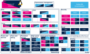
Check boxes illustrate the possible peripheral allocations supported by STM32 MPU Embedded Software:
- ☐ means that the peripheral can be assigned (☑) to the given runtime context.
- ✓ is used for system peripherals that cannot be unchecked because they are statically connected in the device.
Refer to How to assign an internal peripheral to a runtime context for more information on how to assign peripherals manually or via STM32CubeMX.
The present chapter describes STMicroelectronics recommendations or choice of implementation. Additional possiblities might be described in STM32MP15 reference manuals.
| Domain | Peripheral | Runtime allocation | Comment | |||
|---|---|---|---|---|---|---|
| Instance | Cortex-A7 secure (OP-TEE) |
Cortex-A7 non-secure (Linux) |
Cortex-M4 (STM32Cube) | |||
| Core/Timers | TIM | TIM1 (APB2 group) | ☐ | ☐ | Assignment (single choice) | |
| TIM2 (APB1 group) | ☐ | ☐ | Assignment (single choice) | |||
| TIM3 (APB1 group) | ☐ | ☐ | Assignment (single choice) | |||
| TIM4 (APB1 group) | ☐ | ☐ | Assignment (single choice) | |||
| TIM5 (APB1 group) | ☐ | ☐ | Assignment (single choice) | |||
| TIM6 (APB1 group) | ☐ | ☐ | Assignment (single choice) | |||
| TIM7 (APB1 group) | ☐ | ☐ | Assignment (single choice) | |||
| TIM8 (APB2 group) | ☐ | ☐ | Assignment (single choice) | |||
| TIM12 (APB1 group) | ☐ | ☐ | ☐ | Assignment (single choice) | ||
| TIM13 (APB1 group) | ☐ | ☐ | Assignment (single choice) | |||
| TIM14 (APB1 group) | ☐ | ☐ | Assignment (single choice) | |||
| TIM15 (APB2 group) | ☐ | ☐ | ☐ | Assignment (single choice) | ||
| TIM16 (APB2 group) | ☐ | ☐ | Assignment (single choice) | |||
| TIM17 (APB2 group) | ☐ | ☐ | Assignment (single choice) | |||
4. How to go further[edit source]
STM32 cross-series timer overview[8] application note.
5. References[edit source]
Arm® is a registered trademark of Arm Limited (or its subsidiaries) in the US and/or elsewhere. ![]()
Arm® is a registered trademark of Arm Limited (or its subsidiaries) in the US and/or elsewhere. ![]()