1. Article purpose[edit source]
The purpose of this article is to explain how to configure the low-power timer (LPTIM)[1] when the peripheral is assigned to Linux® OS, and in particular:
- how to configure the LPTIM peripheral to enable PWM, trigger, event counter and quadrature encoder
- how to configure the board, e.g. LPTIM input/output pins
The configuration is performed using the device tree mechanism[2].
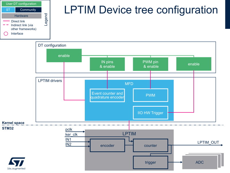
It is used by the LPTIM Linux driver that registers relevant information in PWM, IIO and counter frameworks.
If the peripheral is assigned to another execution context, refer to How to assign an internal peripheral to a runtime context article for guidelines on peripheral assignment and configuration.
2. DT bindings documentation[edit source]
The LPTIM[1] is a multifunction device (MFD).
Each function is represented by a separate binding document:
- STM32 LPTIM MFD device tree bindings[3] deals with core resources (e.g. registers, clock)
- STM32 LPTIM PWM device tree bindings[4] deals with PWM interface resources (e.g. PWM pins)
- STM32 LPTIM trigger device tree bindings[5] deals with LPTIM triggers resources (e.g. trigger output connected to other STM32 internal peripherals)
- STM32 LPTIM counter device tree bindings[6] deals with LPTIM counter and quadrature encoder resources (e.g. counter/encoder IN[1..2] pins)
3. DT configuration[edit source]
This hardware description is a combination of STM32 microprocessor and board device tree files. See Device tree for more explanations on device tree file split.
The STM32CubeMX can be used to generate the board device tree. Refer to How to configure the DT using STM32CubeMX for more details.
3.1. DT configuration (STM32 level)[edit source]
LPTIM nodes are declared in stm32mp151.dtsi[7].
DT root node (aka lptimer1, ..., lptimer5) and DT child nodes describe the LPTIM features such as:
- PWM
- trigger
- event counter and quadrature encoder.
They also describe hardware parameters such as register addresses and clock.
lptimer1: timer@40009000 {
	compatible = "st,stm32-lptimer";                      /* lptimer's common resources */
	...
	pwm {
		compatible = "st,stm32-pwm-lp";               /* PWM part of LPTIM */
	};
	trigger@0 {
		compatible = "st,stm32-lptimer-trigger";      /* trigger part of LPTIM */
		reg = <0>;                                    /* trigger identifier (e.g. 0 for LPTIM1 trigger, 1 for LPTIM2... */
	};
	counter {
		compatible = "st,stm32-lptimer-counter";      /* quadrature encoder & event counter part of LPTIM */
	};
};
3.2. DT configuration (board level)[edit source]
Follow the below sequence to configure and enable the LPTIM on your board STM32MP15 microprocessor:
- Enable DT root node for the LPTIM instance in use (e.g lptimer1, ..., lptimer5), with status = "okay";
- Enable DT child node(s) for the feature(s) in use (PWM output, trigger, event counter and quadrature encoder), with status = "okay";
- Configure the pins in use via pinctrl, with pinctrl-0, pinctrl-1 and pinctrl-names.
3.3. DT configuration examples[edit source]
3.3.1. LPTIM1 configured as PWM and trigger source[edit source]
The example below shows how to configure LPTIM1 to act as:
- PWM output on PG13 (See pinctrl device tree configuration and GPIO internal peripheral)
- trigger source (in Synchronous mode with PWM) for other internal peripherals such as ADC[8], DAC[9], and DFSDM[10]
lppwm1_pins_a: lppwm1-0 {
 	pins {
		pinmux = <STM32_PINMUX('G', 13, AF1)>;    /* configure 'PG13' as alternate 1 for LPTIM1_OUT mode of operation */
		bias-pull-down;
		drive-push-pull;
		slew-rate = <0>;
 	};
};
lppwm1_sleep_pins_a: lppwm1-sleep-0 {
	pins {
		pinmux = <STM32_PINMUX('G', 13, ANALOG)>; /* configure 'PG13' as analog for low power mode */
	};
};
&lptimer1 {
	status = "okay";
	pwm {
		pinctrl-0 = <&lppwm1_pins_a>;             /* configure PWM on LPTIM1_OUT */
		pinctrl-1 = <&lppwm1_sleep_pins_a>;
		pinctrl-names = "default", "sleep";
		status = "okay";                          /* enable PWM on LPTIM1 */
	};
	trigger@0 {
		status = "okay";                          /* enable LPTIM1_OUT trigger source */
	};
};
3.3.2. LPTIM2 configured as counter and quadrature encoder[edit source]
The example below shows how to configure LPTIM2 to act as counter and/or quadrature encoder, with LPTIM2_IN1 and LPTIM2_IN2 pins configured as inputs on PD12 and PD11, respectively (See pinctrl device tree configuration and GPIO internal peripheral)
# part of pin-controller dt node
lptim2_in_pins_a: lptim2-in-pins-0 {
	pins {
		pinmux = <STM32_PINMUX('D', 12, AF3)>, /* LPTIM2_IN1 */
			 <STM32_PINMUX('D', 11, AF3)>; /* LPTIM2_IN2 */
		bias-disabled;
	};
};
lptim2_sleep_in_pins_a: lptim2-sleep-in-pins-0 {
	pins {
		pinmux = <STM32_PINMUX('D', 12, ANALOG)>, /* LPTIM2_IN1 */
			 <STM32_PINMUX('D', 11, ANALOG)>; /* LPTIM2_IN2 */
	};
};
&lptimer2 {
	status = "okay";
	counter {
		pinctrl-0 = <&lptim2_in_pins_a>;          /* configure LPTIM2 counter/encoder pins */
		pinctrl-1 = <&lptim2_sleep_in_pins_a>;
		pinctrl-names = "default", "sleep";
		status = "okay";                          /* enable counter/encoder on LPTIM2 */
	};
};
4. How to configure the DT using STM32CubeMX[edit source]
The STM32CubeMX tool can be used to configure the STM32MPU device and get the corresponding platform configuration device tree files.
The STM32CubeMX may not support all the properties described in the above DT bindings documentation paragraph. If so, the tool inserts user sections in the generated device tree. These sections can then be edited to add some properties and they are preserved from one generation to another. Refer to STM32CubeMX user manual for further information.
5. References[edit source]
For additional information, refer to the following links:
- ↑ Jump up to: 1.0 1.1 LPTIM internal peripheral
- ↑ Device tree
- ↑ Documentation/devicetree/bindings/mfd/stm32-lptimer.txt , STM32 LPTIM MFD device tree bindings
- ↑ Documentation/devicetree/bindings/pwm/pwm-stm32-lp.txt , STM32 LPTIM PWM device tree bindings
- ↑ Documentation/devicetree/bindings/iio/timer/stm32-lptimer-trigger.txt , STM32 LPTIM trigger device tree bindings
- ↑ Documentation/devicetree/bindings/counter/stm32-lptimer-cnt.txt , STM32 LPTIM counter/encoder device tree bindings
- ↑ STM32MP151 device tree file
- ↑ ADC internal peripheral
- ↑ DAC internal peripheral
- ↑ DFSDM internal peripheral