This message will disappear after all relevant tasks have been resolved.
Semantic MediaWiki
There are 1 incomplete or pending task to finish installation of Semantic MediaWiki. An administrator or user with sufficient rights can complete it. This should be done before adding new data to avoid inconsistencies.MB1272 board overview.
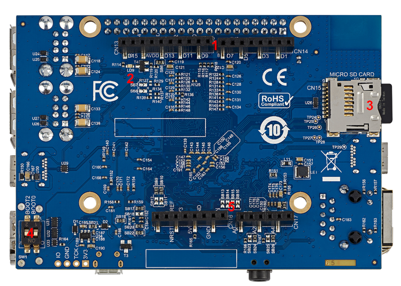
1. Board overview[edit source]
MB1272 motherboard STM32MP157x 12x12 with PMIC and DDR3, revision C-0.1: part of the SSTM32MP157x-DKx Discovery kit ![]() .
.
Note that:
- MB1272 for the STM32MP157A-DK1
 and STM32MP157D-DK1 Discovery kits doesn't include the "WLAN + Bluetooth" component (muRata LBEE5KL1DX)
 - MB1272 for STM32MP157C-DK2 and STM32MP157F-DK2 Discovery kits includes the "WLAN + Bluetooth" component (Murata LBEE5KL1DX)
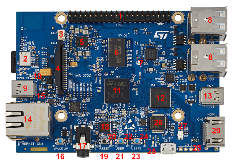
Details of some LEDs:
- LD1: red if USB type A connection established
- LD2: green if power connection established
- LD3: green flashing the Ethernet connection established
- LD4: red flashing if ST-LINK/V2-1 connection not established, else green
- LD5, LD6, LD7, LD8: some user LEDs are used to reflect the system activity, whereas the others are left free and can be directly used by the application, as explained in the LEDs and buttons on STM32 MPU boards article
2. Links[edit source]