Registered User mNo edit summary |
Registered User mNo edit summary |
||
| Line 19: | Line 19: | ||
==Peripheral usage and associated software== | ==Peripheral usage and associated software== | ||
===Boot time=== | ===Boot time=== | ||
DDRCTRL and DDRPHYC are kept secure and used by the [[Boot | DDRCTRL and DDRPHYC are kept secure and used by the [[Boot chain overview|FSBL]] to initialize the access to the DDR where it loads the [[U-Boot overview|SSBL (U-Boot)]] for execution.<br /> | ||
STMicroelectronics wishes to make the DDR memory configuration as easy as possible, for this reason a dedicated application note<ref>[[STM32MP15 resources#AN5168|AN5168 - DDR configuration on STM32MP1 Series MPU]]</ref> has been published and a '''DDR tuning''' function is available in [[STM32CubeMX]] tool in order to generate the [[Device tree|device tree]] configuration that is given to the [[Boot | STMicroelectronics wishes to make the DDR memory configuration as easy as possible, for this reason a dedicated application note<ref>[[STM32MP15 resources#AN5168|AN5168 - DDR configuration on STM32MP1 Series MPU]]</ref> has been published and a '''DDR tuning''' function is available in [[STM32CubeMX]] tool in order to generate the [[Device tree|device tree]] configuration that is given to the [[Boot chain overview|FSBL]] to perform this initialization. | ||
===Runtime=== | ===Runtime=== | ||
====Overview==== | ====Overview==== | ||
DDRCTRL and DDRPHYC are accessed at runtime by the secure monitor (from the [[Boot | DDRCTRL and DDRPHYC are accessed at runtime by the secure monitor (from the [[Boot chain overview|FSBL]] or [[OP-TEE overview|OP-TEE]]) to put the DDR in self-refresh state before going into Stop or Standby [[Power overview|low power mode]].<br /> | ||
On Standby exit, the [[STM32MP15 ROM code overview|ROM code]] loads the [[Boot | On Standby exit, the [[STM32MP15 ROM code overview|ROM code]] loads the [[Boot chain overview|FSBL]] that again configures the DDRCTRL and DDRPHYC before proceeding with the wake-up procedure. | ||
<br /> | <br /> | ||
The [[TZC internal peripheral|TZC]] controller is configured by TF-A to split the DDR in two regions: | The [[TZC internal peripheral|TZC]] controller is configured by TF-A to split the DDR in two regions: | ||
| Line 44: | Line 44: | ||
====Peripheral configuration==== | ====Peripheral configuration==== | ||
The [[DDRCTRL and DDRPHYC device tree configuration]] is generated via [[STM32CubeMX]] tool, according to the DDR characteristics (type, size, frequency, speed grade). This configuration is applied during boot time by the FSBL (see [[Boot | The [[DDRCTRL and DDRPHYC device tree configuration]] is generated via [[STM32CubeMX]] tool, according to the DDR characteristics (type, size, frequency, speed grade). This configuration is applied during boot time by the FSBL (see [[Boot chain overview]]): [[TF-A_overview|TF-A]] or [[U-Boot overview#SPL: FSBL for basic boot|U-Boot SPL]]. | ||
====Peripheral assignment==== | ====Peripheral assignment==== | ||
Latest revision as of 11:39, 25 September 2020
1. Article purpose[edit source]
The purpose of this article is to:
- briefly introduce the DDRCTRL and DDRPHYC peripherals and their main features
- indicate the level of security supported by those hardware blocks
- explain how they can be allocated to the three runtime contexts and linked to the corresponding software components
- explain, when necessary, how to configure the DDRCTRL and DDRPHYC peripherals.
2. Peripheral overview[edit source]
DDRCTRL and DDRPHYC peripherals are used to configure the physical interface to the external DDR memory.
2.1. Features[edit source]
Refer to STM32MP15 reference manuals for the complete features list, and to the software components, introduced below, to see which features are actually implemented.
2.2. Security support[edit source]
DDRCTRL and DDRPHYC are secure aware (under ETZPC control).
Access to the DDR memory can be filtered via the TZC controller: for instance, it is possible to forbid access from the Cortex®-M4 to the DDR region used by the Cortex®-A7.
3. Peripheral usage and associated software[edit source]
3.1. Boot time[edit source]
DDRCTRL and DDRPHYC are kept secure and used by the FSBL to initialize the access to the DDR where it loads the SSBL (U-Boot) for execution.
STMicroelectronics wishes to make the DDR memory configuration as easy as possible, for this reason a dedicated application note[1] has been published and a DDR tuning function is available in STM32CubeMX tool in order to generate the device tree configuration that is given to the FSBL to perform this initialization.
3.2. Runtime[edit source]
3.2.1. Overview[edit source]
DDRCTRL and DDRPHYC are accessed at runtime by the secure monitor (from the FSBL or OP-TEE) to put the DDR in self-refresh state before going into Stop or Standby low power mode.
On Standby exit, the ROM code loads the FSBL that again configures the DDRCTRL and DDRPHYC before proceeding with the wake-up procedure.
The TZC controller is configured by TF-A to split the DDR in two regions:
- the first region, the largest one, is reserved for Linux (Cortex-A7 non-secure context)
- the second region, 32 Mbytes wide, is dedicated for OP-TEE (Cortex-A7 secure context). This area is used by its pager as a cache area from which it can load trusted applications that are authenticated in the SYSRAM internal memory before execution.
This split is visible in the overall memory mapping.
3.2.2. Software frameworks[edit source]
| Domain | Peripheral | Software frameworks | Comment | ||
|---|---|---|---|---|---|
| Cortex-A7 secure (OP-TEE) |
Cortex-A7 non-secure (Linux) |
Cortex-M4 (STM32Cube) | |||
| Core/RAM | DDR via DDRCTRL | Memory mapping | Memory mapping | ||
3.2.3. Peripheral configuration[edit source]
The DDRCTRL and DDRPHYC device tree configuration is generated via STM32CubeMX tool, according to the DDR characteristics (type, size, frequency, speed grade). This configuration is applied during boot time by the FSBL (see Boot chain overview): TF-A or U-Boot SPL.
3.2.4. Peripheral assignment[edit source]
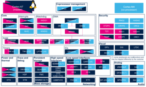
Check boxes illustrate the possible peripheral allocations supported by STM32 MPU Embedded Software:
- ☐ means that the peripheral can be assigned (☑) to the given runtime context.
- ✓ is used for system peripherals that cannot be unchecked because they are statically connected in the device.
Refer to How to assign an internal peripheral to a runtime context for more information on how to assign peripherals manually or via STM32CubeMX.
The present chapter describes STMicroelectronics recommendations or choice of implementation. Additional possiblities might be described in STM32MP15 reference manuals.
| Domain | Peripheral | Runtime allocation | Comment | |||
|---|---|---|---|---|---|---|
| Instance | Cortex-A7 secure (OP-TEE) |
Cortex-A7 non-secure (Linux) |
Cortex-M4 (STM32Cube) | |||
| Core/RAM | DDR via DDRCTRL | DDR | ✓ | ✓ | ||
4. References[edit source]