Target description
The first part of the tutorial:
This tutorial enables you to use ST Motor Profiler and after applying it you can:
- Connect the motor-control Nucleo pack to your computer.
- Start the motor
- Monitor the speed.
The second part of the tutorial:
This tutorial enables you to use STM32 Motor Control SDK and after applying it you can:
- Generate the code to start the motor
- Add delay to the engine
Prerequisites
- Computer with Windows 7 (or higher)
- ST-Link utility installed and updated
Hardware
- P-Nucleo-IHM03 pack[1]
- Standard-A to- Mini-B USB cable + power source
Software
- ST Motor Profiler
For the second part of the tutorial:
- MotorControl Workbench[2]
Literature
- Getting started with STM32 motor-control Nucleo packs[3]
- P-NUCLEO-IHM03 Data brief[4]
- Motor-control overview
- UM2374 STM32 Motor Control SDK user manual.
 Getting started with STM32 Motor Control SDK5.0.
1. Configure your first motor application using ST Motor Profiler
1.1. Install ST Motor Profiler
Get the installation file from this link and unzip it. Then just execute the .exe file so that the installation starts.
Once the installation is done the software is installed on your computer.
The ST Motor Profiler is automatically installed with the STM32 motor-control software Development kit on your computer.
Once the installation is done, it gets installed automatically with the MotorControl Workbench while following the installation steps.

1.2. Connect the package to the computer
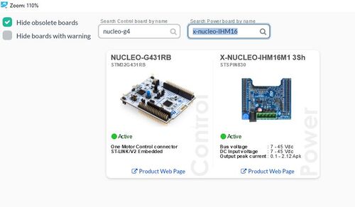
In this tutorial, we are working on the P-NUCLEO-IHM03 motor-control Nucleo pack composed of NUCLEO-G431RB as command board and X-NUCLEO-IHM16M1 as power board.
To start our application we should set up the boards and the power source, and finally connect it to the computer.
After setting up the boards and motor properly, launch the Motor Profiler application.
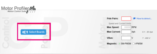
- The first step to do is to select the boards we are using by clicking on Select Boards button
- By referring to the user manual, the following parameters regarding the motor characteristics can be defined and set in the appropriate cases:
- Pole Pairs
- Max Speed
- Max Current
- VBus.
- After defining the values, the next step is to click on the Connect button and check the motor working correctly.
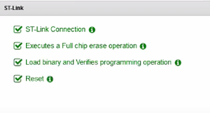
First, ST Motor Profiler creates the following ST-Link checklist to load the added parameters to the software created for the board:
1.3. Start the test
After finishing the connection between the boards and the computer, it is now the time to start the test.
- Click on Start Profile button.
When clicking, the motor starts rotating at a high speed and the electrical, as well as the mechanical models, gets established as shown in the following photo, and if there is any fault it is mentioned on the right of the window.

1.4. Monitor the speed
After checking that the motor is connected and working properly, the next step is to make it work while controlling its speed.
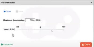
- Click on the Play button and the following window appears.
- By moving the cursor, the speed can be monitored
- Start your motor application
- Set and properly use the ST motor-control Nucleo pack
- Control the acceleration of the motor
2. Start the engine using ST MotorControl Workbench
2.1. Install MotorControl Workbench
For the installation of the MotorControl Workbench, please follow the steps mentioned in the previous part of the tutorial.
2.2. Start the first application
Since the pack used is P-Nucleo-IHM03 it is mandatory to select the appropriate boards used.
First step to do so is to click on New Project and to select the NUCLEO-G431RB as control board & X-NUCLEO-IHM16M1 as power board, then click on OK as enumerated in the next photo:
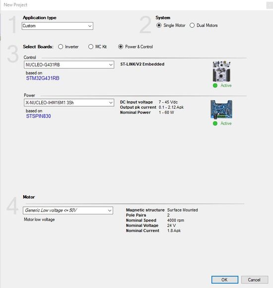
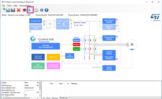
After finishing selecting the pack's boards, another window appears that allows the user to check the details and set the values of the different characteristics.
Later, just click on the generate file button presented in the photo below, and save the project in the appropriate directory.
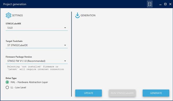
Then a window that allows to choose the IDE to use, and the drive type appears. Just click on Generate and after the software finishes generating the .ioc file, do not change any parameter, just click on Run STM32CubeMX.
The .ioc file is open now and the next step is to simply generate the code in the STM32CubeIDE and do not forget to update the project information in the Project Manager section.
Once the code is generated, the only step to do is to connect the pack and to debug the program.
The program has been installed on the command board and once clicking on the user button, the engine rotates correctly.
2.3. Start the motor and rotate the engine with a delay
In this part, the target work is to start the motor and make it stop with a delay fixed by the user.
The first steps are the same as the previous part until the code generation.
Then, add the following code to the while loop in the main file:
 while (1)
  {
	  MC_StartMotor1();
	  HAL_Delay(2000);
      MC_StopMotor1();
 }
3. Control the motor's direction
In this part, the motor control is based on the direction control.
It is devided into two parts, the first one is the management of the MotorControl Workbench and the second concerns the programming part.
3.1. Changing the MotorControl Workbench parameters
After launching MotorControl Workbench, select the appropriate boards and pack. Later generate a project as presented in the previous parts.
Once generating the project file, click on Firmware Drive Management and then select Drive Setting.
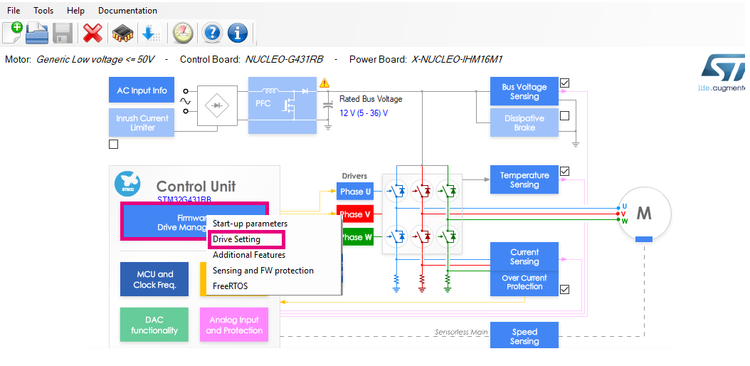
A popup appears, to control the orientation of the motor, select Position Control of the Control mode from the Default settings section.
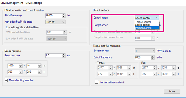
Then, generate code as presented in the Start the first application part.
3.2. Managing the programming code part
Now, to manage the direction of the motor, add the following code
In the declaration part:
int x=0;
Later add the following code in the While loop:
while (1)
{
MC_StartMotor1();
x=x+0.175;
MC_ProgramPositionCommandMotor1(x,0);
}
With x is the angle that we want to direct the motor and the second variable that is set to 0 here represents the time set to reach the position desired.
In this example, we want to motor to keep moving with adding 0.175 to the angle x at every cycle of the loop.
After finish adding the code, build and debug the program generated and see the motor changing its direction.
Now you may:
- Start your first application using MotorControl Workbench
- Generate the motor-control code
- Rotate the engine
- Specify the delay needed between the start and the stop
- Change its direction
3.3. References
