Sensors usage with B-L475E-IOT01A![]() 60min
60min
Target description
The purpose of this tutorial is to explain how to perform measurements with sensors available in the STM32L4 Discovery kit. Configuration of the temperature sensor is described step by step.
After this tutorial, you will be able to collect values using the sensors available on B-L475E-IOT01A board.
The appendix of this tutorial provides guidelines on how to port an AC6 example to STM32CubeIDE.
Prerequisites
You have gone through:
Hardware
- STM32L4 Discovery kit IoT node[1] (B-L475E-IOT01A )
- USB cable Type-A to Micro-B
Literature
- UM2153 Discovery kit for IoT node, multi-channel communication with STM32L4
- UM1884 Description of STM32L4/L4+ HAL and low-layer drivers
- UM1859 Getting started with the X-CUBE-MEMS1 motion MEMS and environmental sensor software expansion for STM32Cube
- UM2579 Migration guide from System Workbench to STM32CubeIDE
 Getting starting with STM32L4 Discovery kit IoT node
1. Sensors usage with B-L475E-IOT01A
1.1. Hardware description
The main sensors available in the STM32L4 Discovery kit IoT node (B-L475E-IOT01A) are:
- Capacitive digital sensor for relative humidity and temperature (HTS221)
- 260-1260 hPa absolute digital output barometer (LPS22HB)
- 3D accelerometer and 3D gyroscope (LSM6DSL)
- High-performance 3-axis magnetometer (LIS3MDL).

1.2. Example: Get temperature values using the HTS221 sensor and display them on a terminal
The purpose of this section is to explain step by step how to interface with the HTS221 sensor to get temperature values and display them on a terminal.
1.2.1. Create a working project with STM32CubeMX
The starting point is the project generated with STM32CubeMX described in the Step3 tutorial titled Introduction to the UART I/F on B-L475E-IOT01A.
Follow the steps described there and call the generated project L4_IOT_Sensors.
1.2.2. Copy BSP drivers to your project
The BSP (board support package) drivers are available in the STM32CubeL4 package. This provides APIs corresponding to the hardware components of a board. The last version of the STM32CubeL4 package is downloaded by default in the STM32CubeMX repository (C:\Users\user_name\STM32Cube\Repository\STM32Cube_FW_L4_Vx.xx.x).
BSP location and content in the tree:

Here are the steps to follow in order to copy the BSP drivers into your project:
- Copy the STM32CubeL4/Drivers/BSP/B-L475E-IOT01 folder
- In the generated project, create a folder L4_IOT_Sensors/Drivers/BSP. Paste the copied folder there.
- Copy the STM32CubeL4/Drivers/BSP/Components folder. Paste it under L4_IOT_Sensors/Drivers/BSP/Components.
- Optional cleanup of working directory: as only the HTS221 temperature sensor is used, some other files and folders already copied to the working directory may be removed
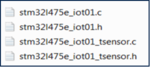
- Under L4_IOT_Sensors\Drivers\BSP\B-L475E-IOT01, keep only the following files:
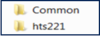
- Under L4_IOT_Sensors\Drivers\BSP\Components, keep only the following folders:
- Under L4_IOT_Sensors\Drivers\BSP\B-L475E-IOT01, keep only the following files:

1.2.3. Support BSP in STM32CubeIDE workspace
After being copied, the added folders appear automatically in the STM32CubeIDE workspace:

1.2.4. Update include paths
Update the paths to support new header files:
- Select the relevant project from the Project Explorer perspective:

- From Project menu or File menu, go to Properties > C/C++ Build > Settings > Tool Settings > MCU GCC Compiler > Include paths
- Click on
 to include the new paths
 - Add ../Drivers/BSP/B-L475E-IOT01 and ../Drivers/BSP/Components/hts221 paths
The following screenshot summarizes the steps to follow:

1.2.5. Update source files
The only file to modify is main.c, as follows:
- Include the header files: stm32l475e_iot01.h, stm32l475e_iot01_tsensor.h and math.h
/* USER CODE BEGIN Includes */<br>
#include "stm32l475e_iot01.h"
#include "stm32l475e_iot01_tsensor.h"
#include <math.h>
/* USER CODE END Includes */
- Add private values to use for temperature values and displayed messages on the terminal:
/* USER CODE BEGIN PV */
/* Private variables -------------------------------------------------------*/
float temp_value = 0;  // Measured temperature value
char str_tmp[100] = ""; // Formatted message to display the temperature value
uint8_t msg1[] = "****** Temperature values measurement ******\n\n\r";
uint8_t msg2[] = "=====> Initialize Temperature sensor HTS221 \r\n";
uint8_t msg3[] = "=====> Temperature sensor HTS221 initialized \r\n ";
/* USER CODE END PV */
- Display messages on the terminal and initialize the HTS221 temperature sensor:
/* USER CODE BEGIN 2 */
HAL_UART_Transmit(&huart1,msg1,sizeof(msg1),1000);
HAL_UART_Transmit(&huart1,msg2,sizeof(msg2),1000);
BSP_TSENSOR_Init();
HAL_UART_Transmit(&huart1,msg3,sizeof(msg3),1000);
/* USER CODE END 2 *//
- In the while (1) loop, read the temperature value, format it, and then display the message with the measured value on the terminal:
/* USER CODE BEGIN 3 */
temp_value = BSP_TSENSOR_ReadTemp();
int tmpInt1 = temp_value;
float tmpFrac = temp_value - tmpInt1;
int tmpInt2 = trunc(tmpFrac * 100);
snprintf(str_tmp,100," TEMPERATURE = %d.%02d\n\r", tmpInt1, tmpInt2);
HAL_UART_Transmit(&huart1,( uint8_t * )str_tmp,sizeof(str_tmp),1000);
HAL_Delay(1000);
/* USER CODE END 3 */
1.2.6. Compile and run the example
- Click on Build button
 to compile the project
 - Click on Debug button
 to run the software
 - Open a console emulator such as TeraTerm [2]. To configure the console baud rate, select data bits: 8 and click OK. Port name may differ on your PC
- STM32CubeIDE opens the Debug perspective. Click on the Resume button
 to execute the code
 - TeraTerm [2] displays the initialization message preceding the measured temperature values:

Now you are able to:
- Build your own project to measure temperature values with the sensor embedded on the B-L475E-IOT01A
- Add BSP components to an STM32CubeMx generated project
- Extend the use of the board to sensors other than HTS221, to make environmental measurements.
2. Appendix: Porting an AC6 example to STM32CubeIDE
The example to be used in this appendix is DataLogTerminal located under: STM32CubeExpansion_MEMS1_V7.1.0\Projects\STM32L476RG-Nucleo\Examples\IKS01A2\DataLogTerminal
2.1. Hardware description
The X-NUCLEO-IKS01A2[3] is a motion MEMS and environmental sensor expansion board for the STM32 64-pin Nucleo. It interfaces with NUCLEO-L476RG via I²C-bus pins.

2.2. Example: Get temperature values using the HTS221 sensor and display them on terminal (Porting from AC6 to STM32CubeIDE)
The purpose of this section is to explain step by step how to interface the X-NUCLEO IKS01A2 HTS221 sensor and NUCLEO-L476RG to get temperature values and display them on a terminal.
2.2.1. Hardware setup
- Extend your Nucleo board with the X-NUCLEO-IKS01A2 shield using the Arduino connectors
- Connect the board with its shield to your PC.
2.2.2. Example details
A description of the DataLogTerminal example is available under STM32CubeExpansion_MEMS1_ V7.1.0\Projects\STM32L476RG-Nucleo\Examples\IKS01A2\DataLogTerminal in the readme.txt file:
@par Example Description
Main function is to show how to use sensor expansion board to send sensor data from a Nucleo board using UART to a connected PC or desktop, and display it on generic applications like TeraTerm.
After connection has been established:
- The user can view the data from various on-board environment sensors such as temperature, humidity, and pressure
- The user can also view data from various on-board MEMS sensors such as accelerometer, gyroscope, and magnetometer.
2.2.3. Porting the example to STM32CubeIDE
Import the DataLogTerminal example based on SW4STM32 and dedicated to the NUCLEO-L476RG into STM32CubeIDE: STM32CubeExpansion_MEMS1_V7.1.0\Projects\STM32L476RG-Nucleo\Examples\IKS01A2\DataLogTerminal.
The project must be converted and the following message is displayed:

- When clicking on OK, the following message pops up:

- Click OK
- Select the relevant project from the Project Explorer perspective:

2.2.4. Compiling and running the example
- Click on the Build button to compile the project.
- Click on the Debug button arrow
 and select Debug Configurations...
 - In the Debug Configuration window that pops up, make sure that the selected Debug probe is ST-LINK:

- From the same window, click on Debug, or click on the Debug button to run the software.
- Open a console emulator such as TeraTerm [2]. Configure the Console baud rate, select Data bits: 8 and click OK. The port name may differ on your PC.
- Click on the Resume button to execute the code. TeraTerm [2] displays the measured values using the sensors available in the shield X-NUCLEO-IKS01A2.
- The values measured by the X-NUCLEO-IKS01A2 sensors are displayed in the TeraTerm window as follows:

3. References