Registered User mNo edit summary |
Registered User mNo edit summary Tag: 2017 source edit |
||
| (144 intermediate revisions by 4 users not shown) | |||
| Line 1: | Line 1: | ||
<big><big><big>''' | <big><big><big>'''Using sensors with B-L475E-IOT01A and with B-U585I-IOT02A'''</big></big></big>[[File:Clock.png|40px|middle]]60min<br><br> | ||
<big><big>'''Target description'''</big></big><br> | <big><big>'''Target description'''</big></big><br> | ||
The purpose of this tutorial is to explain how to perform measurements with sensors available in the STM32L4 Discovery kit. | The purpose of this tutorial is to explain how to perform measurements with the sensors available in the STM32L4 Discovery kit and in the B-U585I-IOT02A Discovery kit. A step by step configuration of the temperature sensor is available. <br> | ||
After this tutorial, you will be able to collect values using the sensors available on B-L475E-IOT01A board.<br> | After this tutorial, you will be able to collect values using the sensors available on the B-L475E-IOT01A board and on the B-U585I-IOT02A board.<br> | ||
The appendix of this tutorial provides guidelines on how to port an AC6 example to STM32CubeIDE.<br> | The appendix of this tutorial provides guidelines on how to port an AC6 example to STM32CubeIDE.<br> | ||
<big><big>'''Prerequisites'''</big></big><br> | <big><big>'''Prerequisites'''</big></big><br> | ||
You | You already followed:<br> | ||
* [[STM32StepByStep:Step1 Tools installation | Step1: Tools installation and first test]]<br> | * [[STM32StepByStep:Step1 Tools installation | Step1: Tools installation and first test]]<br> | ||
* [[STM32StepByStep:Step3 Introduction to the UART | Step3: UART and new board introduction]]<br> | * [[STM32StepByStep:Step3 Introduction to the UART | Step3: UART and new board introduction]]<br> | ||
| Line 13: | Line 13: | ||
* STM32L4 Discovery kit IoT node<ref>[https://www.st.com/en/evaluation-tools/b-l475e-iot01a.html STM32L4 Discovery kit IoT node]</ref> (B-L475E-IOT01A )<br> | * STM32L4 Discovery kit IoT node<ref>[https://www.st.com/en/evaluation-tools/b-l475e-iot01a.html STM32L4 Discovery kit IoT node]</ref> (B-L475E-IOT01A )<br> | ||
* B-U585I-IOT02A Discovery kit IoT node<ref>[https://www.st.com/en/evaluation-tools/b-u585i-iot02a.html B-U585I-IOT02A Discovery kit IoT node]</ref> (B-U585I-IOT02A )<br> | |||
* USB cable Type-A to Micro-B | * USB cable Type-A to Micro-B | ||
| Line 18: | Line 19: | ||
* [https://www.st.com/resource/en/user_manual/dm00347848.pdf UM2153] Discovery kit for IoT node, multi-channel communication with STM32L4<br> | * [https://www.st.com/resource/en/user_manual/dm00347848.pdf UM2153] Discovery kit for IoT node, multi-channel communication with STM32L4<br> | ||
* [http://www.st.com/content/ccc/resource/technical/document/user_manual/63/a8/8f/e3/ca/a1/4c/84/DM00173145.pdf/files/DM00173145.pdf/jcr:content/translations/en.DM00173145.pdf UM1884] Description of STM32L4/L4+ HAL and low-layer drivers<br> | * [http://www.st.com/content/ccc/resource/technical/document/user_manual/63/a8/8f/e3/ca/a1/4c/84/DM00173145.pdf/files/DM00173145.pdf/jcr:content/translations/en.DM00173145.pdf UM1884] Description of STM32L4/L4+ HAL and low-layer drivers<br> | ||
* [https://www.st.com/resource/en/user_manual/um2839-discovery-kit-for-iot-node-with-stm32u5-series-stmicroelectronics.pdf UM2839] Discovery kit for IoT node with STM32U5 Series<br> | |||
* [https://www.st.com/content/ccc/resource/technical/document/user_manual/group2/17/c1/76/07/05/1c/4e/fb/DM00813340/files/DM00813340.pdf/jcr:content/translations/en.DM00813340.pdf UM2911] Description of STM32U5 HAL and low-layer drivers<br> | |||
* [https://www.st.com/resource/en/user_manual/dm00157069.pdf UM1859] Getting started with the X-CUBE-MEMS1 motion MEMS and environmental sensor software expansion for STM32Cube<br> | * [https://www.st.com/resource/en/user_manual/dm00157069.pdf UM1859] Getting started with the X-CUBE-MEMS1 motion MEMS and environmental sensor software expansion for STM32Cube<br> | ||
* [https://www.st.com/resource/en/user_manual/dm00613836-migration-guide-from-system-workbench-to-stm32cubeide-stmicroelectronics.pdf UM2579] Migration guide from System Workbench to STM32CubeIDE<br> | * [https://www.st.com/resource/en/user_manual/dm00613836-migration-guide-from-system-workbench-to-stm32cubeide-stmicroelectronics.pdf UM2579] Migration guide from System Workbench to STM32CubeIDE<br> | ||
* [[File:pc_videol.png|middle|20px|link=https://www.youtube.com/watch?v=6eUqxjBL_wI]] [https://www.youtube.com/watch?v=6eUqxjBL_wI Getting | * [[File:pc_videol.png|middle|20px|link=https://www.youtube.com/watch?v=6eUqxjBL_wI]] [https://www.youtube.com/watch?v=6eUqxjBL_wI Getting started with STM32L4 Discovery kit IoT node]<br> | ||
* [[File:pc_videol.png|middle|20px|link=https://www.youtube.com/watch?v=Zo10SQaU7jA]] [https://www.youtube.com/watch?v=Zo10SQaU7jA Discover the new STM32U5 IoT node B-U585-IOT02A Discovery kit]<br> | |||
<br> | <br> | ||
== | ==Using sensors with B-L475E-IOT01A== | ||
===Hardware description=== | ===Hardware description=== | ||
The main sensors available in the STM32L4 Discovery kit IoT node (B-L475E-IOT01A) are:<br> | The main sensors available in the STM32L4 Discovery kit IoT node (B-L475E-IOT01A) are:<br> | ||
| Line 29: | Line 33: | ||
* 3D accelerometer and 3D gyroscope (LSM6DSL)<br> | * 3D accelerometer and 3D gyroscope (LSM6DSL)<br> | ||
* High-performance 3-axis magnetometer (LIS3MDL).<br> | * High-performance 3-axis magnetometer (LIS3MDL).<br> | ||
[[File:IoTNode_Board_Sensor.png|middle| | [[File:IoTNode_Board_Sensor.png|middle|600px]]<br> | ||
<br> | <br> | ||
===Example: | ===Example: Getting temperature values using the HTS221 sensor and displaying them on a terminal=== | ||
{{Highlight|The purpose of this section is to | {{Highlight|The purpose of this section is to provide a step by step description on how to interface with the HTS221 sensor to get temperature values and to display them on a terminal.}}<br> | ||
====Create a working project with STM32CubeMX==== | ====Create a working project with STM32CubeMX==== | ||
The starting point is the project generated with STM32CubeMX described in the Step3 tutorial | The starting point is the project generated with STM32CubeMX, described in the Step3 tutorial : [[STM32StepByStep:Step3 Introduction to the UART#Introduction to the UART I/F on B-L475E-IOT01A (IoT Node)| Introduction to the UART I/F on B-L475E-IOT01A]].<br> | ||
Follow the steps | * Follow the steps in the tutorial. <br> | ||
* Name the generated project as L4_IOT_Sensors.<br> | |||
====Copy BSP drivers to your project==== | ====Copy BSP drivers to your project==== | ||
The '''''BSP''''' (board support package) drivers are available in the '''''STM32CubeL4 package'''''. This provides APIs corresponding to the hardware components of a board. The | The '''''BSP''''' (board support package) drivers are available in the '''''STM32CubeL4 package'''''. This provides APIs corresponding to the hardware components of a board. <br> | ||
'''''BSP''''' location and content | |||
The lastest version of the STM32CubeL4 package is downloaded by default in the STM32CubeMX repository: | |||
'''''C:\Users\user_name\STM32Cube\Repository\STM32Cube_FW_L4_Vx.xx.x'''''.<br> | |||
The image below shows the '''''BSP''''' location and its content:<br> | |||
[[File:Folder_tree.png|middle|150px]]<br> | [[File:Folder_tree.png|middle|150px]]<br> | ||
{{info|STM32CubeL4 used | {{info|In this example, the STM32CubeL4 version used is 1.11.0. Version can increase over time.}} | ||
Follow these steps to copy the BSP drivers to your project:<br> | |||
* In the generated project, create a folder '''''L4_IOT_Sensors/Drivers/BSP'''''. | |||
* Copy the '''''STM32CubeL4/Drivers/BSP/B-L475E-IOT01''''' folder | |||
* Copy the '''''STM32CubeL4/Drivers/BSP/B-L475E-IOT01''''' folder and paste it in the '''''L4_IOT_Sensors/Drivers/BSP''''' folder. | |||
* Copy the '''''STM32CubeL4/Drivers/BSP/Components''''' folder | |||
* | * Copy the '''''STM32CubeL4/Drivers/BSP/Components''''' folder and paste it under '''''L4_IOT_Sensors/Drivers/BSP/Components'''''. | ||
* | |||
* | * Only the HTS221 temperature sensor is used. For this reason, any other files and folders copied to the working directory can be removed. This step is optional: | ||
* Keep only the following files under '''''L4_IOT_Sensors\Drivers\BSP\B-L475E-IOT01''''':<br> | |||
[[File:Folder_tree_2.png|middle|150px]]<br> | |||
* Keep only the following files under '''''L4_IOT_Sensors\Drivers\BSP\Components''''':<br> | |||
[[File:Folder_tree_3.png|middle|100px]]<br> | |||
====Support BSP in STM32CubeIDE workspace==== | ====Support BSP in STM32CubeIDE workspace==== | ||
Added folders appear automatically in the STM32CubeIDE workspace:<br> | |||
[[File:Folder_tree_4.png|middle|150px]]<br> | [[File:Folder_tree_4.png|middle|150px]]<br> | ||
<br> | <br> | ||
| Line 60: | Line 76: | ||
* Select the relevant project from the '''''Project Explorer''''' perspective: | * Select the relevant project from the '''''Project Explorer''''' perspective: | ||
[[File:Project_select.png|middle|300px]]<br> | [[File:Project_select.png|middle|300px]]<br> | ||
* From '''''Project menu''''' or '''''File menu''''', go to '''''Properties > C/C++ Build > Settings > Tool Settings > MCU GCC Compiler > Include paths'''''<br> | * From '''''Project menu''''' or '''''File menu''''', go to '''''Properties > C/C++ Build > Settings > Tool Settings > MCU GCC Compiler > Include paths'''''.<br> | ||
* Click on [[File:Add_icon.png|middle|30px]] to include the new paths <br> | * Click on [[File:Add_icon.png|middle|30px]] to include the new paths. <br> | ||
* Add '''''../Drivers/BSP/B-L475E-IOT01''''' and '''''../Drivers/BSP/Components/hts221''''' paths<br> | * Add '''''../Drivers/BSP/B-L475E-IOT01''''' and '''''../Drivers/BSP/Components/hts221''''' paths.<br> | ||
The following screenshot summarizes the steps to follow:<br> | The following screenshot summarizes the steps to follow:<br> | ||
[[File:Project_setting.png|middle|450px]]<br> | [[File:Project_setting.png|middle|450px]]<br> | ||
====Update source files==== | ====Update source files==== | ||
Edit '''''main.c''''' as follows:<br> | |||
* Include the header files: '''''stm32l475e_iot01.h''''', '''''stm32l475e_iot01_tsensor.h''''' and '''''math.h''''' | * Include the header files: '''''stm32l475e_iot01.h''''', '''''stm32l475e_iot01_tsensor.h''''' and '''''math.h'''''<br> | ||
<syntaxhighlight lang="c">/* USER CODE BEGIN Includes */ | <syntaxhighlight lang="c">/* USER CODE BEGIN Includes */ | ||
#include "stm32l475e_iot01.h" | #include "stm32l475e_iot01.h" | ||
#include "stm32l475e_iot01_tsensor.h" | #include "stm32l475e_iot01_tsensor.h" | ||
#include <math.h> | #include <math.h> | ||
/* USER CODE END Includes */</syntaxhighlight> | /* USER CODE END Includes */</syntaxhighlight> | ||
* Add private values to | * Add private values. These values are used to display temperature and messages on the terminal: | ||
<syntaxhighlight lang="c">/* USER CODE BEGIN PV */ | <syntaxhighlight lang="c">/* USER CODE BEGIN PV */ | ||
/* Private variables -------------------------------------------------------*/ | /* Private variables -------------------------------------------------------*/ | ||
| Line 96: | Line 112: | ||
int tmpInt2 = trunc(tmpFrac * 100); | int tmpInt2 = trunc(tmpFrac * 100); | ||
snprintf(str_tmp,100," TEMPERATURE = %d.%02d\n\r", tmpInt1, tmpInt2); | snprintf(str_tmp,100," TEMPERATURE = %d.%02d\n\r", tmpInt1, tmpInt2); | ||
HAL_UART_Transmit(&huart1,( uint8_t * )str_tmp,sizeof(str_tmp),1000); | HAL_UART_Transmit(&huart1,( uint8_t *)str_tmp,sizeof(str_tmp),1000); | ||
HAL_Delay(1000); | HAL_Delay(1000); | ||
/* USER CODE END 3 */</syntaxhighlight> | /* USER CODE END 3 */</syntaxhighlight> | ||
{{info| | {{info|Updates must only be made on the required '''''USER CODE''''' section, to avoid overwriting all the content with a new STM32CubeMX code generation.}} | ||
====Compile and run the example==== | ====Compile and run the example==== | ||
* Click on '''''Build''''' button [[File:Built_Button.png|20px|middle]] to compile the project<br> | * Click on the '''''Build''''' button [[File:Built_Button.png|20px|middle]] to compile the project.<br> | ||
* Click on '''''Debug''''' button [[File:Debug_Button.png|20px|middle]] to run the software<br> | * Click on the '''''Debug''''' button [[File:Debug_Button.png|20px|middle]] to run the software.<br> | ||
* Open a console emulator such as TeraTerm <ref name="TeraTerm" >[https://ttssh2.osdn.jp/index.html.en TeraTerm]</ref>. To configure the console baud rate, select data bits: 8 and click OK. Port name may differ on your | * Open a console emulator such as TeraTerm <ref name="TeraTerm" >[https://ttssh2.osdn.jp/index.html.en TeraTerm]</ref>. To configure the console baud rate, select '''data bits: 8''' and click '''OK'''. Port name may differ on your computer.<br> | ||
* STM32CubeIDE opens the '''''Debug perspective'''''. Click on the '''''Resume''''' button [[File:Resume_Button.png|20px|middle]] to execute the code<br> | * STM32CubeIDE opens the '''''Debug perspective'''''. Click on the '''''Resume''''' button [[File:Resume_Button.png|20px|middle]] to execute the code.<br> | ||
* TeraTerm <ref name="TeraTerm" /> displays the initialization message preceding the measured temperature values:<br> | * TeraTerm <ref name="TeraTerm" /> displays the initialization message preceding the measured temperature values:<br> | ||
[[File:TeraTerm_Temp.png|middle|300px]]<br> | [[File:TeraTerm_Temp.png|middle|300px]]<br> | ||
{{Highlight|Now you are able to}}: | |||
* Build your own project to measure temperature values using the embedded sensor in B-L475E-IOT01A.<br> | |||
* Add BSP components to an STM32CubeMx generated project.<br> | |||
* Extend the use of the board to sensors other than HTS221, to make environmental measurements. | |||
==Using sensors with B-U585-IOT02A== | |||
===Hardware description=== | |||
The main sensors available in B-U585I-IOT02A discovery kit for the IoT node are:<br> | |||
* Capacitive digital sensor for relative humidity and temperature (HTS221)<br> | |||
* 260-1260 hPa absolute digital output barometer (LPS22HH)<br> | |||
* 3D accelerometer and 3D gyroscope (ISM330DHCX)<br> | |||
* High-performance 3-axis magnetometer (IIS2MDCTR).<br> | |||
[[File:IoTNode_Board_SensorU5.png|middle|600px]]<br> | |||
<br> | |||
===Example: Getting temperature values using the HTS221 sensor and displaying them on a terminal=== | |||
{{Highlight|The purpose of this section is to provide a step by step description on how to interface with the HTS221 sensor to get temperature values and to display them on a terminal.}}<br> | |||
====Create a working project with STM32CubeMX==== | |||
Create a new project using STM32CubeMX: | |||
* Select the '''''B-U585I-IOT02A''''' board using the '''''Board selector'''''.<br> | |||
* Answer '''''Yes''''' to '''''Initialize all peripherals with their default Mode ?''''' popup.<br> | |||
* Select '''''without TrustZone activated?'''''. Answer '''''OK''''' to the '''''Create a new project without TrustZone activated?''''' popup.<br> | |||
* Verify in the '''''Pinout''''' tab that the '''''USART1''''' mode is configured to '''Asynchronous'''.<br> | |||
* Click on the '''''USART1''''' button in the '''''Configuration''''' tab. Set '''''Word Length''''' to '''''8 Bits''''', baud rate to '''''115200 Bits/s''''', '''''Parity''''' to '''''None '''''and '''''Stop Bits''''' to '''''1''''', as shown below:<br> | |||
[[File:UART_setup2.png|middle|300px]]<br> | |||
* Enable '''''ICache''''' in the '''''Pinout''''' tab by selecting '''''Memory address remap''''' to reach the maximum performance'''''.<br> | |||
* Switch to the '''''Project Manager''''' tab: Select '''''STM32CubeIDE''''' as Toolchain/IDE and name your project. <br> | |||
* Click on '''''Generate Code'''''. | |||
* Accept to open the project in STM32CubeIDE and follow the steps. | |||
* Call the generated project U5_IOT_Sensors.<br> | |||
====Copy BSP drivers to your project==== | |||
The '''''BSP''''' (board support package) drivers are available in the '''''STM32CubeU5 package'''''. This provides APIs corresponding to the hardware components of a board. | |||
The lastest version of the STM32CubeU5 package is downloaded by default in the SMT32CubeMX repository: | |||
'''''C:\Users\user_name\STM32Cube\Repository\STM32Cube_FW_U5_Vx.xx.x'''''.<br> | |||
The image below shows the '''''BSP''''' location and its content:<br> | |||
[[File:BSP.png|middle|150px]]<br> | |||
{{info|In this example, the STM32CubeU5 version used is 1.1.1. Version can increase over time.}} | |||
Here are the steps to follow in order to copy the BSP drivers to your project:<br> | |||
* In the generated project, create a folder '''''U5_IOT_Sensors/Drivers/BSP'''''. | |||
* Copy the '''''STM32CubeU5/Drivers/BSP/B-U585-IOT02''''' folder and paste it to the '''''U5_IOT_Sensors/Drivers/BSP''''' folder.<br> | |||
* Copy the '''''STM32CubeU5/Drivers/BSP/Components''''' folder and paste it under '''''U5_IOT_Sensors/Drivers/BSP/Components'''''.<br> | |||
* Only the HTS221 temperature sensor is used. For this reason, any other files and folders copied to the working directory can be removed. This step is optional: <br> | |||
* Keep only the following folders under '''''U5_IOT_Sensors\Drivers\BSP\Components''''':<br> | |||
[[File:Components_drivers.png|middle|100px]]<br> | |||
*Keep only the following folders under '''''U5_IOT_Sensors\Drivers\BSP\B-U585-IOT02''''':<br> | |||
[[File:b_u585i_iot2 drivers.png|middle|150px]]<br> | |||
* Rename the file '''''b_u585i_iot02a_conf_template.h''''' to '''''b_u585i_iot02a_conf.h'''''.<br> | |||
====Support BSP in STM32CubeIDE workspace==== | |||
Added folders appear automatically in the STM32CubeIDE workspace:<br> | |||
[[File:Project_with_BSP_Drivers.png|middle|200px]]<br> | |||
<br> | |||
====Update include paths==== | |||
Update the paths to support new header files:<br> | |||
* Select the relevant project from the '''''Project Explorer''''' perspective: | |||
[[File:Project_name.png|middle|300px]]<br> | |||
* From '''''Project menu''''' or '''''File menu''''', go to '''''Properties > C/C++ Build > Settings > Tool Settings > MCU GCC Compiler > Include paths'''''.<br> | |||
* Click on [[File:Add_icon.png|middle|30px]] to include the new paths. <br> | |||
* Add the paths '''''../Drivers/BSP/B-U585I-IOT02A''''' , '''''../Drivers/BSP/Components/hts221''''' and '''''../Drivers/BSP/Components/lps22hh'''''<br> | |||
The following screenshot summarizes the steps to follow:<br> | |||
[[File:Path1.png|middle|450px]]<br> | |||
====Update source files==== | |||
Edit '''''main.c''''' as follows:<br> | |||
* Include the header files: '''''b_u585i_iot02a.h''''', '''''b_u585i_iot02a_env_sensors.h''''' and '''''math.h'''''<br> | |||
<syntaxhighlight lang="c">/* USER CODE BEGIN Includes */ | |||
#include "b_u585i_iot02a.h" | |||
#include "b_u585i_iot02a_env_sensors.h" | |||
#include <math.h> | |||
/* USER CODE END Includes */</syntaxhighlight> | |||
* Add private values. These values are used to display temperature and messages on the terminal: | |||
<syntaxhighlight lang="c">/* USER CODE BEGIN PV */ | |||
/* Private variables -------------------------------------------------------*/ | |||
float temp_value = 0; // Measured temperature value | |||
char str_tmp[100] = ""; // Formatted message to display the temperature value | |||
uint8_t msg1[] = "****** Temperature values measurement ******\n\n\r"; | |||
uint8_t msg2[] = "=====> Initialize Temperature sensor HTS221 \r\n"; | |||
uint8_t msg3[] = "=====> Temperature sensor HTS221 initialized \r\n"; | |||
/* USER CODE END PV */</syntaxhighlight> | |||
* Display messages on the terminal and initialize the HTS221 temperature sensor: | |||
<syntaxhighlight lang="c">/* USER CODE BEGIN 2 */ | |||
HAL_UART_Transmit(&huart1,msg1,sizeof(msg1),1000); | |||
HAL_UART_Transmit(&huart1,msg2,sizeof(msg2),1000); | |||
BSP_ENV_SENSOR_Init(0, ENV_TEMPERATURE); | |||
BSP_ENV_SENSOR_Enable(0, ENV_TEMPERATURE); | |||
HAL_UART_Transmit(&huart1,msg3,sizeof(msg3),1000); | |||
/* USER CODE END 2 *//</syntaxhighlight> | |||
* In the '''''while (1)''''' loop, read the temperature value, format it, and then display the message with the measured value on the terminal: | |||
<syntaxhighlight lang="c">/* USER CODE BEGIN 3 */ | |||
BSP_ENV_SENSOR_GetValue(0, ENV_TEMPERATURE, &temp_value); | |||
int tmpInt1 = temp_value; | |||
float tmpFrac = temp_value - tmpInt1; | |||
int tmpInt2 = trunc(tmpFrac * 100); | |||
snprintf(str_tmp,100," TEMPERATURE = %d.%02d\n\r", tmpInt1, tmpInt2); | |||
HAL_UART_Transmit(&huart1,( uint8_t *)str_tmp,sizeof(str_tmp),1000); | |||
HAL_Delay(1000); | |||
/* USER CODE END 3 */</syntaxhighlight> | |||
{{info|Updates must only be made on the required USER CODE section, to avoid overwriting all the content with a new STM32CubeMX code generation.}} | |||
====Compile and run the example==== | |||
* Click on the '''''Build''''' button [[File:Built_Button.png|20px|middle]] to compile the project.<br> | |||
* Click on the '''''Debug''''' button [[File:Debug_Button.png|20px|middle]] to run the software.<br> | |||
* Open a console emulator such as TeraTerm <ref name="TeraTerm" >[https://ttssh2.osdn.jp/index.html.en TeraTerm]</ref>. To configure the console baud rate, select '''data bits: 8''' and click '''OK'''. Port name may differ on your computer.<br> | |||
* STM32CubeIDE opens the '''''Debug perspective'''''. Click on the '''''Resume''''' button [[File:Resume_Button.png|20px|middle]] to execute the code.<br> | |||
* TeraTerm <ref name="TeraTerm" /> displays the initialization message preceding the measured temperature values:<br> | |||
[[File:tera_term_temp.png|middle|400px]]<br> | |||
{{Highlight|Now you are able to}}: | {{Highlight|Now you are able to}}: | ||
* Build your own project to measure temperature values | * Build your own project to measure temperature values using the embedded sensor in B-U585I-IOT02A.<br> | ||
* Add BSP components to an STM32CubeMx generated project<br> | * Add BSP components to an STM32CubeMx generated project.<br> | ||
* Extend the use of the board to sensors other than HTS221, to make environmental measurements. | * Extend the use of the board to sensors other than HTS221, to make environmental measurements. | ||
==Appendix: Porting an AC6 example to STM32CubeIDE== | ==Appendix: Porting an AC6 example to STM32CubeIDE== | ||
'''''DataLogTerminal''''' is the example used in this appendix. | |||
It is located in: '''''STM32CubeExpansion_MEMS1_V7.1.0\Projects\STM32L476RG-Nucleo\Examples\IKS01A2\DataLogTerminal'''''<br> | |||
{{info|STM32CubeExpansion_MEMS1_V7.1.0 is the extract of [http://www.st.com/en/embedded-software/x-cube-mems1.html X-CUBE-MEMS]. More recent versions of this package may be available over time from the same link.}} | {{info|STM32CubeExpansion_MEMS1_V7.1.0 is the extract of [http://www.st.com/en/embedded-software/x-cube-mems1.html X-CUBE-MEMS]. More recent versions of this package may be available over time from the same link.}} | ||
{{Warning | | {{Warning | In order to prevent future compilation errors due to long paths, it is recommended to place the package under C:. }} | ||
===Hardware description=== | ===Hardware description=== | ||
The X-NUCLEO-IKS01A2<ref>[https://www.st.com/content/st_com/en/products/ecosystems/stm32-open-development-environment/stm32-nucleo-expansion-boards/stm32-ode-sense-hw/x-nucleo-iks01a2.html X-NUCLEO-IKS01A2]</ref> is a motion MEMS and environmental sensor expansion board for the STM32 64-pin Nucleo. It interfaces with [https://www.st.com/en/evaluation-tools/nucleo-l476rg.html NUCLEO-L476RG] via I²C-bus pins.<br> | The X-NUCLEO-IKS01A2<ref>[https://www.st.com/content/st_com/en/products/ecosystems/stm32-open-development-environment/stm32-nucleo-expansion-boards/stm32-ode-sense-hw/x-nucleo-iks01a2.html X-NUCLEO-IKS01A2]</ref> is a motion MEMS and environmental sensor expansion board for the STM32 64-pin Nucleo. It interfaces with [https://www.st.com/en/evaluation-tools/nucleo-l476rg.html NUCLEO-L476RG] via I²C-bus pins.<br> | ||
[[File:IKS_Sensor_Board.png|middle|450px]]<br> | [[File:IKS_Sensor_Board.png|middle|450px]]<br> | ||
===Example: | ===Example: Getting temperature values using the HTS221 sensor and displaying them on a terminal (Porting from AC6 to STM32CubeIDE)=== | ||
The purpose of this section is to | The purpose of this section is to provide a step by step description on how to interface the X-NUCLEO IKS01A2 '''''HTS221''''' sensor and the NUCLEO-L476RG board in order to obtain temperature values and to display them on a terminal.<br> | ||
====Hardware setup==== | ====Hardware setup==== | ||
* Extend your Nucleo board with the X-NUCLEO-IKS01A2 shield using the Arduino connectors<br> | * Extend your Nucleo board with the X-NUCLEO-IKS01A2 shield using the Arduino connectors.<br> | ||
* Connect the board with its shield to your | * Connect the board with its shield to your computer.<br> | ||
====Example details==== | ====Example details==== | ||
A description of the '''''DataLogTerminal''''' example is available under '''''STM32CubeExpansion_MEMS1_ V7.1.0\Projects\STM32L476RG-Nucleo\Examples\IKS01A2\DataLogTerminal''''' in the '''''readme.txt''''' file: | A description of the '''''DataLogTerminal''''' example is available under '''''STM32CubeExpansion_MEMS1_ V7.1.0\Projects\STM32L476RG-Nucleo\Examples\IKS01A2\DataLogTerminal''''', in the '''''readme.txt''''' file: | ||
<syntaxhighlight lang="c"> | <syntaxhighlight lang="c"> | ||
@par Example Description | @par Example Description | ||
| Line 137: | Line 283: | ||
====Porting the example to STM32CubeIDE==== | ====Porting the example to STM32CubeIDE==== | ||
Import the '''''DataLogTerminal''''' example based on '''''SW4STM32''''' and dedicated to the '''''NUCLEO-L476RG''''' into STM32CubeIDE: | Import the '''''DataLogTerminal''''' example based on '''''SW4STM32''''' and dedicated to the '''''NUCLEO-L476RG''''' into STM32CubeIDE: | ||
''STM32CubeExpansion_MEMS1_V7.1.0\Projects\STM32L476RG-Nucleo\Examples\IKS01A2\DataLogTerminal''<br> | |||
The project must be converted and the following message is displayed:<br> | The project must be converted and the following message is displayed:<br> | ||
[[File:Project_Converter_2.png|middle|300px]]<br> | [[File:Project_Converter_2.png|middle|300px]]<br> | ||
* When clicking on '''''OK''''', the following message pops up: | * When clicking on '''''OK''''', the following message pops up: | ||
[[File:Project_Converter_OK.png|middle|300px]]<br> | [[File:Project_Converter_OK.png|middle|300px]]<br> | ||
* Click '''''OK''''' | |||
* Click '''''OK'''''. | |||
* Select the relevant project from the '''''Project Explorer''''' perspective: | * Select the relevant project from the '''''Project Explorer''''' perspective: | ||
[[File:Project_Explorer.png|middle|300px]]<br> | [[File:Project_Explorer.png|middle|300px]]<br> | ||
====Compiling and running the example==== | ====Compiling and running the example==== | ||
* Click on the '''''Build''''' button [[File:Built_Button.png|20px|middle]] to compile the project.<br> | * Click on the '''''Build''''' button [[File:Built_Button.png|20px|middle]] to compile the project.<br> | ||
* Click on the '''''Debug | * Click on the '''''Debug arrow''''' [[File:Debug_Arrow_Button.png|40px|middle]] and select '''''Debug Configurations''''.<br> | ||
* In the Debug Configuration window that pops up, make sure that the selected Debug | * In the '''Debug Configuration''' window that pops up, make sure that the selected '''Debug probe''' is '''''ST-LINK''''': | ||
[[File:Debug_Panel.png|middle|450px]]<br> | [[File:Debug_Panel.png|middle|450px]]<br> | ||
* From the same window, click on '''''Debug''''', or click on the '''''Debug''''' button [[File:Debug_Button.png|20px|middle]] to run the software.<br> | * From the same window, click on '''''Debug''''', or click on the '''''Debug''''' button [[File:Debug_Button.png|20px|middle]] to run the software.<br> | ||
* Open a console emulator such as TeraTerm <ref name="TeraTerm" />. Configure the Console baud rate, select Data bits: 8 and click '''''OK'''''. The port name may differ on your | * Open a console emulator such as TeraTerm <ref name="TeraTerm" />. Configure the Console baud rate, select '''Data bits: 8''' and click '''''OK'''''. The port name may differ on your computer.<br> | ||
* Click on the '''''Resume''''' button [[File:Resume_Button.png|20px|middle]] to execute the code. TeraTerm <ref name="TeraTerm" /> displays the measured values using the sensors available in the shield X-NUCLEO-IKS01A2.<br> | * Click on the '''''Resume''''' button [[File:Resume_Button.png|20px|middle]] to execute the code. TeraTerm <ref name="TeraTerm" /> displays the measured values using the sensors available in the shield X-NUCLEO-IKS01A2.<br> | ||
* The values measured by the X-NUCLEO-IKS01A2 sensors are displayed in the TeraTerm window as follows: | * The values measured by the X-NUCLEO-IKS01A2 sensors are displayed in the TeraTerm window as follows: | ||
| Line 167: | Line 318: | ||
|} | |} | ||
<noinclude> | |||
[[Category:Getting started with STM32|13]] | |||
{{PublicationRequestId | 27173| 2023-05-12 | }} | |||
{{PublicationRequestId | 16010| 2020-05-05 | Philip SAGE}} | {{PublicationRequestId | 16010| 2020-05-05 | Philip SAGE}} | ||
{{ArticleBasedOnModel | Example STM32 Step by step article}} | {{ArticleBasedOnModel | Example STM32 Step by step article}} | ||
</noinclude> | </noinclude> | ||
Latest revision as of 16:23, 27 May 2024
Using sensors with B-L475E-IOT01A and with B-U585I-IOT02A![]() 60min
60min
Target description
The purpose of this tutorial is to explain how to perform measurements with the sensors available in the STM32L4 Discovery kit and in the B-U585I-IOT02A Discovery kit. A step by step configuration of the temperature sensor is available.
After this tutorial, you will be able to collect values using the sensors available on the B-L475E-IOT01A board and on the B-U585I-IOT02A board.
The appendix of this tutorial provides guidelines on how to port an AC6 example to STM32CubeIDE.
Prerequisites
You already followed:
Hardware
- STM32L4 Discovery kit IoT node[1] (B-L475E-IOT01A )
- B-U585I-IOT02A Discovery kit IoT node[2] (B-U585I-IOT02A )
- USB cable Type-A to Micro-B
Literature
- UM2153 Discovery kit for IoT node, multi-channel communication with STM32L4
- UM1884 Description of STM32L4/L4+ HAL and low-layer drivers
- UM2839 Discovery kit for IoT node with STM32U5 Series
- UM2911 Description of STM32U5 HAL and low-layer drivers
- UM1859 Getting started with the X-CUBE-MEMS1 motion MEMS and environmental sensor software expansion for STM32Cube
- UM2579 Migration guide from System Workbench to STM32CubeIDE
 Getting started with STM32L4 Discovery kit IoT node
 Discover the new STM32U5 IoT node B-U585-IOT02A Discovery kit
1. Using sensors with B-L475E-IOT01A
1.1. Hardware description
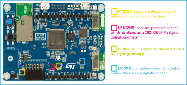
The main sensors available in the STM32L4 Discovery kit IoT node (B-L475E-IOT01A) are:
- Capacitive digital sensor for relative humidity and temperature (HTS221)
- 260-1260 hPa absolute digital output barometer (LPS22HB)
- 3D accelerometer and 3D gyroscope (LSM6DSL)
- High-performance 3-axis magnetometer (LIS3MDL).
1.2. Example: Getting temperature values using the HTS221 sensor and displaying them on a terminal
The purpose of this section is to provide a step by step description on how to interface with the HTS221 sensor to get temperature values and to display them on a terminal.
1.2.1. Create a working project with STM32CubeMX
The starting point is the project generated with STM32CubeMX, described in the Step3 tutorial : Introduction to the UART I/F on B-L475E-IOT01A.
- Follow the steps in the tutorial.
- Name the generated project as L4_IOT_Sensors.
1.2.2. Copy BSP drivers to your project
The BSP (board support package) drivers are available in the STM32CubeL4 package. This provides APIs corresponding to the hardware components of a board.
The lastest version of the STM32CubeL4 package is downloaded by default in the STM32CubeMX repository:
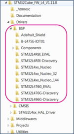
C:\Users\user_name\STM32Cube\Repository\STM32Cube_FW_L4_Vx.xx.x.
The image below shows the BSP location and its content:
| File:Info.png | In this example, the STM32CubeL4 version used is 1.11.0. Version can increase over time. |
Follow these steps to copy the BSP drivers to your project:
- In the generated project, create a folder L4_IOT_Sensors/Drivers/BSP.
- Copy the STM32CubeL4/Drivers/BSP/B-L475E-IOT01 folder and paste it in the L4_IOT_Sensors/Drivers/BSP folder.
- Copy the STM32CubeL4/Drivers/BSP/Components folder and paste it under L4_IOT_Sensors/Drivers/BSP/Components.
- Only the HTS221 temperature sensor is used. For this reason, any other files and folders copied to the working directory can be removed. This step is optional:
* Keep only the following files under L4_IOT_Sensors\Drivers\BSP\B-L475E-IOT01:
* Keep only the following files under L4_IOT_Sensors\Drivers\BSP\Components:
1.2.3. Support BSP in STM32CubeIDE workspace
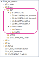
Added folders appear automatically in the STM32CubeIDE workspace:
1.2.4. Update include paths
Update the paths to support new header files:
- Select the relevant project from the Project Explorer perspective:
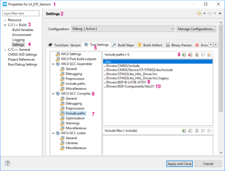
- From Project menu or File menu, go to Properties > C/C++ Build > Settings > Tool Settings > MCU GCC Compiler > Include paths.
- Click on
 to include the new paths.
 - Add ../Drivers/BSP/B-L475E-IOT01 and ../Drivers/BSP/Components/hts221 paths.
The following screenshot summarizes the steps to follow:
1.2.5. Update source files
Edit main.c as follows:
- Include the header files: stm32l475e_iot01.h, stm32l475e_iot01_tsensor.h and math.h
/* USER CODE BEGIN Includes */
#include "stm32l475e_iot01.h"
#include "stm32l475e_iot01_tsensor.h"
#include <math.h>
/* USER CODE END Includes */
- Add private values. These values are used to display temperature and messages on the terminal:
/* USER CODE BEGIN PV */
/* Private variables -------------------------------------------------------*/
float temp_value = 0;  // Measured temperature value
char str_tmp[100] = ""; // Formatted message to display the temperature value
uint8_t msg1[] = "****** Temperature values measurement ******\n\n\r";
uint8_t msg2[] = "=====> Initialize Temperature sensor HTS221 \r\n";
uint8_t msg3[] = "=====> Temperature sensor HTS221 initialized \r\n ";
/* USER CODE END PV */
- Display messages on the terminal and initialize the HTS221 temperature sensor:
/* USER CODE BEGIN 2 */
HAL_UART_Transmit(&huart1,msg1,sizeof(msg1),1000);
HAL_UART_Transmit(&huart1,msg2,sizeof(msg2),1000);
BSP_TSENSOR_Init();
HAL_UART_Transmit(&huart1,msg3,sizeof(msg3),1000);
/* USER CODE END 2 *//
- In the while (1) loop, read the temperature value, format it, and then display the message with the measured value on the terminal:
/* USER CODE BEGIN 3 */
temp_value = BSP_TSENSOR_ReadTemp();
int tmpInt1 = temp_value;
float tmpFrac = temp_value - tmpInt1;
int tmpInt2 = trunc(tmpFrac * 100);
snprintf(str_tmp,100," TEMPERATURE = %d.%02d\n\r", tmpInt1, tmpInt2);
HAL_UART_Transmit(&huart1,( uint8_t *)str_tmp,sizeof(str_tmp),1000);
HAL_Delay(1000);
/* USER CODE END 3 */
| File:Info.png | Updates must only be made on the required USER CODE section, to avoid overwriting all the content with a new STM32CubeMX code generation. |
1.2.6. Compile and run the example
- Click on the Build button
 to compile the project.
 - Click on the Debug button
 to run the software.
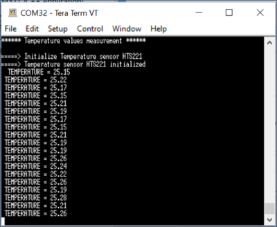
 - Open a console emulator such as TeraTerm [3]. To configure the console baud rate, select data bits: 8 and click OK. Port name may differ on your computer.
- STM32CubeIDE opens the Debug perspective. Click on the Resume button
 to execute the code.
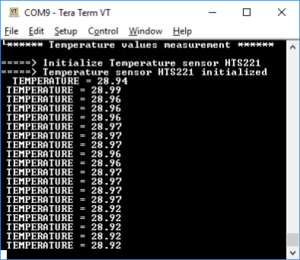
 - TeraTerm [3] displays the initialization message preceding the measured temperature values:
Now you are able to:
- Build your own project to measure temperature values using the embedded sensor in B-L475E-IOT01A.
- Add BSP components to an STM32CubeMx generated project.
- Extend the use of the board to sensors other than HTS221, to make environmental measurements.
2. Using sensors with B-U585-IOT02A
2.1. Hardware description
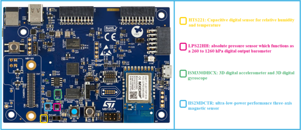
The main sensors available in B-U585I-IOT02A discovery kit for the IoT node are:
- Capacitive digital sensor for relative humidity and temperature (HTS221)
- 260-1260 hPa absolute digital output barometer (LPS22HH)
- 3D accelerometer and 3D gyroscope (ISM330DHCX)
- High-performance 3-axis magnetometer (IIS2MDCTR).
2.2. Example: Getting temperature values using the HTS221 sensor and displaying them on a terminal
The purpose of this section is to provide a step by step description on how to interface with the HTS221 sensor to get temperature values and to display them on a terminal.
2.2.1. Create a working project with STM32CubeMX
Create a new project using STM32CubeMX:
- Select the B-U585I-IOT02A board using the Board selector.
- Answer Yes to Initialize all peripherals with their default Mode ? popup.
- Select without TrustZone activated?. Answer OK to the Create a new project without TrustZone activated? popup.
- Verify in the Pinout tab that the USART1 mode is configured to Asynchronous.
- Click on the USART1 button in the Configuration tab. Set Word Length to 8 Bits, baud rate to 115200 Bits/s, Parity to None and Stop Bits to 1, as shown below:
- Enable ICache in the Pinout tab by selecting Memory address remap to reach the maximum performance.
- Switch to the Project Manager tab: Select STM32CubeIDE as Toolchain/IDE and name your project.
- Click on Generate Code.
- Accept to open the project in STM32CubeIDE and follow the steps.
- Call the generated project U5_IOT_Sensors.
2.2.2. Copy BSP drivers to your project
The BSP (board support package) drivers are available in the STM32CubeU5 package. This provides APIs corresponding to the hardware components of a board.
The lastest version of the STM32CubeU5 package is downloaded by default in the SMT32CubeMX repository:
C:\Users\user_name\STM32Cube\Repository\STM32Cube_FW_U5_Vx.xx.x.
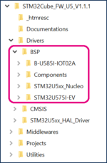
The image below shows the BSP location and its content:
| File:Info.png | In this example, the STM32CubeU5 version used is 1.1.1. Version can increase over time. |
Here are the steps to follow in order to copy the BSP drivers to your project:
- In the generated project, create a folder U5_IOT_Sensors/Drivers/BSP.
- Copy the STM32CubeU5/Drivers/BSP/B-U585-IOT02 folder and paste it to the U5_IOT_Sensors/Drivers/BSP folder.
- Copy the STM32CubeU5/Drivers/BSP/Components folder and paste it under U5_IOT_Sensors/Drivers/BSP/Components.
- Only the HTS221 temperature sensor is used. For this reason, any other files and folders copied to the working directory can be removed. This step is optional:
* Keep only the following folders under U5_IOT_Sensors\Drivers\BSP\Components:
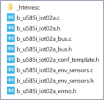
*Keep only the following folders under U5_IOT_Sensors\Drivers\BSP\B-U585-IOT02:
- Rename the file b_u585i_iot02a_conf_template.h to b_u585i_iot02a_conf.h.
2.2.3. Support BSP in STM32CubeIDE workspace
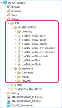
Added folders appear automatically in the STM32CubeIDE workspace:
2.2.4. Update include paths
Update the paths to support new header files:
- Select the relevant project from the Project Explorer perspective:
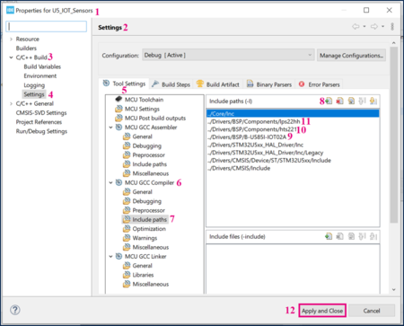
- From Project menu or File menu, go to Properties > C/C++ Build > Settings > Tool Settings > MCU GCC Compiler > Include paths.
- Click on
 to include the new paths.
 - Add the paths ../Drivers/BSP/B-U585I-IOT02A , ../Drivers/BSP/Components/hts221 and ../Drivers/BSP/Components/lps22hh
The following screenshot summarizes the steps to follow:
2.2.5. Update source files
Edit main.c as follows:
- Include the header files: b_u585i_iot02a.h, b_u585i_iot02a_env_sensors.h and math.h
/* USER CODE BEGIN Includes */
#include "b_u585i_iot02a.h"
#include "b_u585i_iot02a_env_sensors.h"
#include <math.h>
/* USER CODE END Includes */
- Add private values. These values are used to display temperature and messages on the terminal:
/* USER CODE BEGIN PV */
/* Private variables -------------------------------------------------------*/
float temp_value = 0;  // Measured temperature value
char str_tmp[100] = ""; // Formatted message to display the temperature value
uint8_t msg1[] = "****** Temperature values measurement ******\n\n\r";
uint8_t msg2[] = "=====> Initialize Temperature sensor HTS221 \r\n";
uint8_t msg3[] = "=====> Temperature sensor HTS221 initialized \r\n";
/* USER CODE END PV */
- Display messages on the terminal and initialize the HTS221 temperature sensor:
/* USER CODE BEGIN 2 */
HAL_UART_Transmit(&huart1,msg1,sizeof(msg1),1000);
HAL_UART_Transmit(&huart1,msg2,sizeof(msg2),1000);
BSP_ENV_SENSOR_Init(0, ENV_TEMPERATURE);
BSP_ENV_SENSOR_Enable(0, ENV_TEMPERATURE);
HAL_UART_Transmit(&huart1,msg3,sizeof(msg3),1000);
/* USER CODE END 2 *//
- In the while (1) loop, read the temperature value, format it, and then display the message with the measured value on the terminal:
/* USER CODE BEGIN 3 */
BSP_ENV_SENSOR_GetValue(0, ENV_TEMPERATURE, &temp_value);
int tmpInt1 = temp_value;
float tmpFrac = temp_value - tmpInt1;
int tmpInt2 = trunc(tmpFrac * 100);
snprintf(str_tmp,100," TEMPERATURE = %d.%02d\n\r", tmpInt1, tmpInt2);
HAL_UART_Transmit(&huart1,( uint8_t *)str_tmp,sizeof(str_tmp),1000);
HAL_Delay(1000);
/* USER CODE END 3 */
| File:Info.png | Updates must only be made on the required USER CODE section, to avoid overwriting all the content with a new STM32CubeMX code generation. |
2.2.6. Compile and run the example
- Click on the Build button
 to compile the project.
 - Click on the Debug button
 to run the software.
 - Open a console emulator such as TeraTerm [3]. To configure the console baud rate, select data bits: 8 and click OK. Port name may differ on your computer.
- STM32CubeIDE opens the Debug perspective. Click on the Resume button
 to execute the code.
 - TeraTerm [3] displays the initialization message preceding the measured temperature values:
- Build your own project to measure temperature values using the embedded sensor in B-U585I-IOT02A.
- Add BSP components to an STM32CubeMx generated project.
- Extend the use of the board to sensors other than HTS221, to make environmental measurements.
3. Appendix: Porting an AC6 example to STM32CubeIDE
DataLogTerminal is the example used in this appendix.
It is located in: STM32CubeExpansion_MEMS1_V7.1.0\Projects\STM32L476RG-Nucleo\Examples\IKS01A2\DataLogTerminal
| File:Info.png | STM32CubeExpansion_MEMS1_V7.1.0 is the extract of X-CUBE-MEMS. More recent versions of this package may be available over time from the same link. |
| In order to prevent future compilation errors due to long paths, it is recommended to place the package under C:. |
3.1. Hardware description
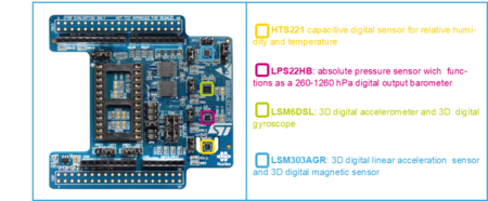
The X-NUCLEO-IKS01A2[4] is a motion MEMS and environmental sensor expansion board for the STM32 64-pin Nucleo. It interfaces with NUCLEO-L476RG via I²C-bus pins.
3.2. Example: Getting temperature values using the HTS221 sensor and displaying them on a terminal (Porting from AC6 to STM32CubeIDE)
The purpose of this section is to provide a step by step description on how to interface the X-NUCLEO IKS01A2 HTS221 sensor and the NUCLEO-L476RG board in order to obtain temperature values and to display them on a terminal.
3.2.1. Hardware setup
- Extend your Nucleo board with the X-NUCLEO-IKS01A2 shield using the Arduino connectors.
- Connect the board with its shield to your computer.
3.2.2. Example details
A description of the DataLogTerminal example is available under STM32CubeExpansion_MEMS1_ V7.1.0\Projects\STM32L476RG-Nucleo\Examples\IKS01A2\DataLogTerminal, in the readme.txt file:
@par Example Description
Main function is to show how to use sensor expansion board to send sensor data from a Nucleo board using UART to a connected PC or desktop, and display it on generic applications like TeraTerm.
After connection has been established:
- The user can view the data from various on-board environment sensors such as temperature, humidity, and pressure
- The user can also view data from various on-board MEMS sensors such as accelerometer, gyroscope, and magnetometer.
3.2.3. Porting the example to STM32CubeIDE
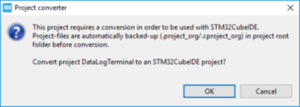
Import the DataLogTerminal example based on SW4STM32 and dedicated to the NUCLEO-L476RG into STM32CubeIDE:
STM32CubeExpansion_MEMS1_V7.1.0\Projects\STM32L476RG-Nucleo\Examples\IKS01A2\DataLogTerminal
The project must be converted and the following message is displayed:
- When clicking on OK, the following message pops up:
- Click OK.
- Select the relevant project from the Project Explorer perspective:
3.2.4. Compiling and running the example
- Click on the Build button
 to compile the project.
 - Click on the Debug arrow
 and select Debug Configurations'.
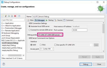
 - In the Debug Configuration window that pops up, make sure that the selected Debug probe is ST-LINK:
- From the same window, click on Debug, or click on the Debug button
 to run the software.
 - Open a console emulator such as TeraTerm [3]. Configure the Console baud rate, select Data bits: 8 and click OK. The port name may differ on your computer.
- Click on the Resume button
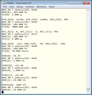
 to execute the code. TeraTerm [3] displays the measured values using the sensors available in the shield X-NUCLEO-IKS01A2.
 - The values measured by the X-NUCLEO-IKS01A2 sensors are displayed in the TeraTerm window as follows:
4. References
