This article explains Sleep, Stop, Standby and Low Power modes, and provides code examples.
1. Low Power mode
By default, the microcontroller is in Run mode after a system or power-on reset. Several low-power modes are available to save power when the CPU does not need to be kept running, for example when waiting for an external event. It is up to the user to select the mode that gives the best compromise between low power consumption, short startup time and available wakeup sources. The main three low-power modes are:
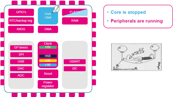
- Sleep mode (Cortex core stopped, peripherals kept running)
- Stop mode (all clocks are stopped)
- Standby mode (only the backup domain is powered).
2. Sleep mode
2.1. Definition
2.1.1. Using Sleep mode with EXTI
2.1.1.1. Objective
- Use the EXTI setup from EXTI overview
- Learn how to set up Sleep mode in the HAL
- Create a simple project with Sleep mode and wakeup when a button (configured in the EXTI setup) is pressed.
2.1.1.2. How
- Use the project from EXTI overview
- Learn how to set up Sleep mode in the HAL, and which events can wake up the MCU
- Verify the correct functionality by measuring the current consumption.
2.1.1.3. HAL library workflow summary
2.1.1.4. Open the project from EXTI overview
- Open main.c
- Add a function to suspend the Systick (as we wakeup on any interrupt)
- Add a function to enter Sleep mode
- Add a function to resume the Systick on wakeup.
/* Infinite loop */
/* USER CODE BEGIN WHILE */
while (1)
{
    HAL_Delay(1000);
    HAL_SuspendTick();
    HAL_PWR_EnterSLEEPMode(PWR_LOWPOWERREGULATOR_ON,PWR_SLEEPENTRY_WFI);
    HAL_ResumeTick();
  /* USER CODE END WHILE */

  /* USER CODE BEGIN 3 */
}
/* USER CODE END 3 */
2.1.1.5. Compile and Flash
Compile the above code, then load it to the board Flash memory.
2.1.1.6. Measure consumption
- Stop any debug session and do a full power cycle
- Use an ammeter on the IDD connector (JP5 on NucleoF429ZI - for other boards check their user manual)
- Check the consumption while in Sleep mode
- Press the configured button on the Nucleo board to see the current consumption variation.
3. Stop mode
3.1. Definition
3.1.1. Use Stop mode with EXTI
3.1.1.1. Objective
- Use the EXTI setup from EXTI overview
- Learn how to set up Stop in the HAL
- Create a simple project with Stop mode with wakeup when a button (configured in the EXTI setup) is pressed.
3.1.1.2. Goals
- Use the project from EXTI overview
- Learn how to set up the Stop mode in the HAL, and which events can wake up the MCU
- Verify the correct functionality by measuring the current consumption.
3.1.1.3. HAL Library workflow summary
3.1.1.4. Open the project from EXTI overview
- Open main.c
- Add a function to enter Stop mode
- Reconfiguration of the clocking
/* Infinite loop */
/* USER CODE BEGIN WHILE */
while (1)
{
    HAL_Delay(1000);
    HAL_SuspendTick();
    HAL_PWR_EnterSTOPMode(PWR_LOWPOWERREGULATOR_ON,PWR_STOPENTRY_WFI);
    SystemClock_Config();
  /* USER CODE END WHILE */

  /* USER CODE BEGIN 3 */
}
/* USER CODE END 3 */
3.1.1.5. Compile and Flash
Compile the above code, then load it to the board Flash memory.
3.1.1.6. Measure consumption
- Stop any debug session and do a full power cycle
- Use an ammeter on the IDD connector (JP5 on NucleoF429ZI - for other boards check their user manual)
- Check the current consumption while in Stop mode
- Press the configured button on the Nucleo board to see the consumption variation.
4. Standby mode
4.1. Definition
4.1.1. Use Standby mode
4.1.1.1. Objective
- For this lab, create an STM32CubeMX project
- For testing purposes, enable LED PG14 on the NucleoF429ZI (for other boards check their user manual)
- Learn how to set up Standby mode in the HAL
- Create a simple project with Standby mode and wakeup when the associated button is pressed.
4.1.1.2. Goals
- Learn how to set up Standby mode in the HAL, and which events can wake up you
- Verify the correct functionality by measuring the current consumption.
4.1.1.3. HAL Library workflow summary
4.1.1.4. Open the project from EXTI overview
- Open main.c
- Add the wakeup flag clear (without this, Standby mode is only entered once)
/* Initialize all configured peripherals */
/* USER CODE BEGIN 2 */
__HAL_PWR_CLEAR_FLAG(PWR_FLAG_WU);
/* USER CODE END 2 */
- Turn on the LED
- Wait 2 seconds
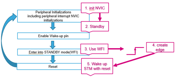
- Enable the wakeup pin (which is PA0 and is connected to the blue button on the NucleoF429ZI)
- Add a function to enter Standby mode.
/* Infinite loop */
/* USER CODE BEGIN WHILE */
while (1)
{
    HAL_GPIO_TogglePin(GPIOG, GPIO_PIN_14);
    HAL_Delay(2000);
    HAL_PWR_EnableWakeUpPin(PWR_WAKEUP_PIN1);
    HAL_PWR_EnterSTANDBYMode();
  /* USER CODE END WHILE */

  /* USER CODE BEGIN 3 */
}
/* USER CODE END 3 */
4.1.1.5. Compile and Flash
Compile the above code, then load it to the board Flash memory.
4.1.1.6. Measure consumption
- Stop any debug session and do a full power cycle
- Use an ammeter on the IDD connector (JP5 on NucleoF429ZI - for other boards check their user manual)
- Check the current consumption while in Standby mode
- Press the blue Nucleo button to see the consumption variation.
5. Useful power monitoring tool
A dedicated tool exists for power consumption measurement : STM32CubeMonPwr

