This article explains what HRTIM is and how to use it through examples.
1. What is an HRTIM ?
HRTIM stands for high-resolution timer. HRTIM is a highly accurate timer that can generate complex waveforms such as PWM, phase-shifted. It is made up of six 16-bit up counter and a controller timer with very highly fine timing resolution (184 ps on the STM32G4 series). They can be used independently or synchronized. HRTIM applications are various: from digital power conversion (digital SMPS, solar converters, motor control) to also for general-purpose applications.
1.1. Counter operating modes
Up-counters can operate in three modes:
- Continuous (also called Free-running): it rolls over to zero when it exceeds the value programmed in the period register (HRTIM_PERxR)
- Single shot Retriggerable: It starts with a reset event occurs and stops when it reaches the period value (HRTIM_PERxR). In this mode, the user can reset at any time.
- Single shot non-retriggerable : The same principle as single shot retriggerable but in this mode, reset events are discarded if they occur before the end of the counting phase.
1.2. Block diagram overview
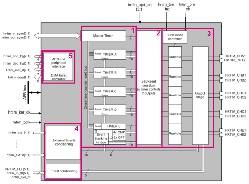
As we can see on the figure below, the HRTIM have a modular architecture. Let us have a look at each block:
- Block 1 Timing units are six 16-bit upcounter with a programmable overflow, two capture registers and four compare registers. Compare event can be generated when the counter is equal to the compare value (HRTIM_CMP1xR).
- Block 2 Set/Reset Crossbar allows having the output pairs controlled not only by a related timing unit but by external event and other timers.
- Block 3 Output stage manage a pair of outputs with any kind of logic (polarity, safe states, asynchronous fault protection...).
- Block 4 Input block includes 10 external events, five fault signals (protect the power stages and shutdown PWM outputs).
- Block 5 Interface part link the HRTimer with other timers, DMA, ADC, and DAC with internal STM32 connections.
2. Configure the HRTIM to generate a simple PWM
2.1. Objective
- In this project, you learn how to set up HRTIM in STM32CubeIDE
- How to generate code in STM32CubeIDE and use HAL functions
- Provide a simple application to create a single PWM
- Configure timer in continuous mode, crossbar, and output stage
2.2. Creating the project in STM32CubeIDE
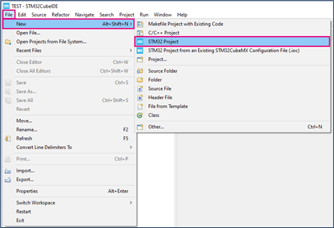
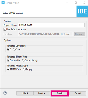
- File > New > STM32 Project in a main panel.
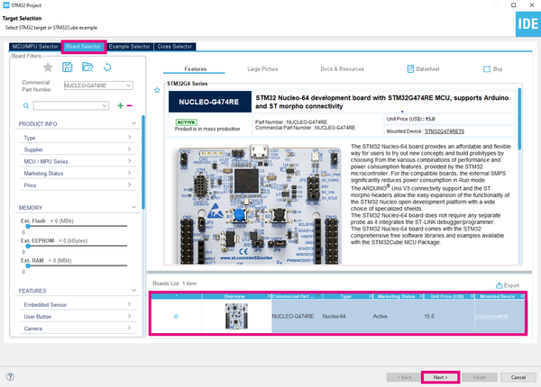
- Select the NUCLEO-G474RE board using the Board Selector, as shown in the figure below:
- Answer Yes to initialize all peripherals with their default mode? Popup as below:
- If not downloaded previously, the download of the STM32CubeG4 Cube library starts automatically. The download may take some time.
- Save the project.
2.3. Configure HRTIM
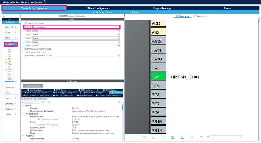
- In the Pinout & Configuration window, select HRTIM1 and choose TA1 output active.
- In User Constants, click on add and enter this constant name TIMA_DUTY_CYCLE with the value 0.5.
- In Timer A, in section Time Base Setting , observe the configuration: up_counting and continuous mode with a resulting PWM Frequency of 83050 Hz (Period = 0xFFDF). Keep the settings.
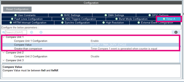
- Scroll down until Compare Unit 1, and fill as below :
- Enable Compare Unit 1 Configuration
- Enter 0xFFDF * TIMA_DUTY_CYCLE in the Compare Value
- Keep Timer Compare 1 event is generated when counter is equal
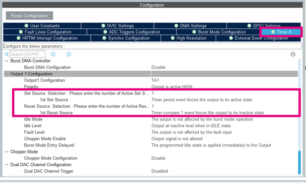
- Scroll down until Output 1 Configuration and fill as below:
- Enter 1 as number of Active Set Source and select Timer period event forces the output to its active state as the first set source
- Enter 1 as number of Active Reset Source and select Timer compare 1 event forces the output to its inactive state as the first reset source
2.4. Generate project and edit main.c
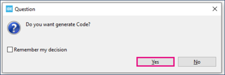
- Click Ctrl+S to generate the project.
- Open Project.
- Edit main.c as the picture below:
  /* USER CODE BEGIN 2 */

  /* Enable HRTIM's outputs TA1 and start Timer A */
  HAL_HRTIM_WaveformOutputStart(&hhrtim1, HRTIM_OUTPUT_TA1);  // Enable the generation of the waveform signal on the designated output
  HAL_HRTIM_WaveformCounterStart(&hhrtim1, HRTIM_TIMERID_TIMER_A);  // Start the counter of the Timer A operating in waveform mode

  /* USER CODE END 2 */
2.5. Compile and flash
- Click on Build button
 .
. - Click on Debug button (to run step by step)
 .
. - Or on Run button (to execute)
 .
.
3. Result
If you want to observe the output PWM, you need to check on the CN9 the pin n°8 named D7 with an oscilloscope.
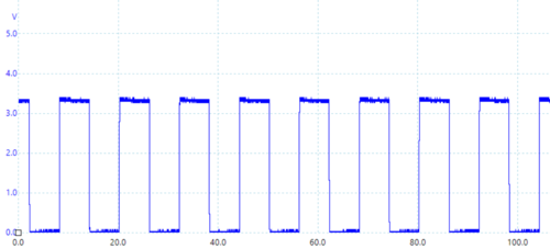
- For a duty cycle of 0.5, we have the waveform below:
- Open and edit main.h.
- In the private defines section, change the value of TIMA_DUTY_CYCLE such as the picture below.
/* Private defines --------------------------------------*/
#define TIMA_DUTY_CYCLE 0.8
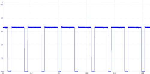
- For a duty cycle of 0.8, we have the waveform below:
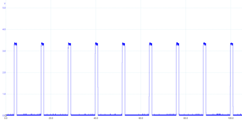
- For a duty cycle of 0.1, we have the waveform below:
4. To go further about DMA burst
The DMA burst controller allows:
- Update multiple registers (such as the CMP1xR to control the duty cycle of the PWM).
- Reprogram dynamically one or several timing units.
Go back in CubeMX in the HRTIM1 configuration in Timer A / Time Base Setting :
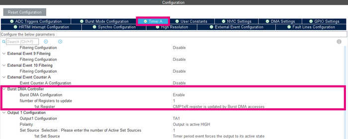
- Enable the Burst DMA configuration.
- Enter 1 in the number of register to update.
- Choose CMP1xR register is updated by Burst DMA accesses as the first register.
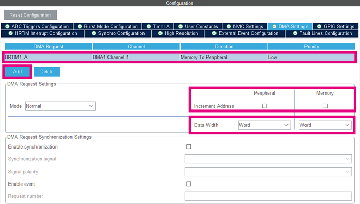
Then, go in the DMA settings window, and configure as shown in the picture below:
- Click on Add.
- Select HRTIM1_A in DMA request.
- Uncheck Increment address boxes (for both peripheral and memory).
- Choose Word for data width (for both peripheral and memory).
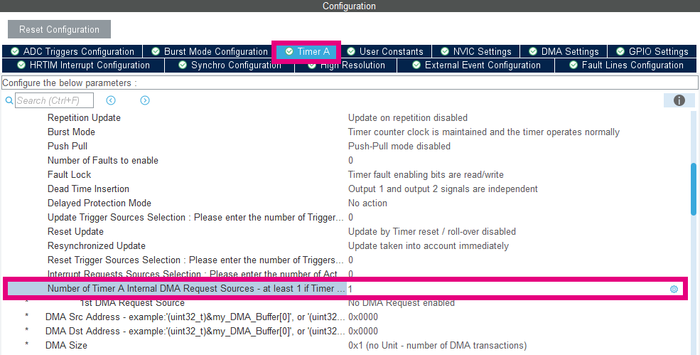
The last changes in the DMA settings window created a warning in Timer A / Timing Unit / Number of Timer A Internal DMA request sources. Enter 1 instead of 0 like in the picture below :
Next, generate the code and edit the main.c a second time. (See generate project and edit main.c.)
/* USER CODE BEGIN 2 */

/* Enable HRTIM outputs TA1 and start Timer A */
HAL_HRTIM_WaveformOutputStart(&hhrtim1, HRTIM_OUTPUT_TA1);  // Enable the generation of the waveform signal on the designated output
HAL_HRTIM_WaveformCounterStart(&hhrtim1, HRTIM_TIMERID_TIMER_A);  // Start the counter of the Timer A operating in waveform mode

static uint32_t Reg_Update [] =
{
   0xFFA0,
};
if(HAL_HRTIM_BurstDMATransfer(&hhrtim1, HRTIM_TIMERINDEX_TIMER_A, (uint32_t) Reg_Update, sizeof(Reg_Update)/sizeof(uint32_t)) != HAL_OK) //Add a breakpoint here
{
   Error_Handler();
}

/* USER CODE END 2 */
HAL_HRTIM_BurstDMAConfig(): configures the burst DMA burst controller. It allows having multiple HRTIM registers updated with a single DMA request. The burst DMA operation is started by calling HAL_HRTIM_BurstDMATransfer().
For the last step, go in the function HAL_HRTIM_MspInit() where the HRTIM1 DMA is initialize. Declare the direction to DMA_MEMORY_TO_MEMORY and not DMA_MEMORY_TO_PERIPH.
hdma_hrtim1_a.Init.Direction = DMA_MEMORY_TO_MEMORY;
"The DMA channels may operate without being triggered by a request from a peripheral. This mode is called memory-to-memory mode, and is initiated by software." (extract from chapter DMA in RM0440)
