This article explains how to use the RTC. It provides code examples to use RTC Alarm with interrupt.
1. What is a Real Time Clock (RTC)?
A RTC is an independent binary-coded decimal (BCD) timer/counter. The RTC provides a time-of-day clock/calendar with programmable alarm interrupt. In addition, the RTC can provide an automatic wakeup to manage all low-power modes. For STM32L476, main RTC features are the following:
- Calendar with subseconds, seconds, minutes, hours, day, date of day in month, month and year.
- Daylight saving compensation programmable by software.
- Programmable alarm with interrupt function.
- Automatic wakeup unit generating a periodic flag that triggers an automatic wakeup interrupt.
- Reference clock detection: a more precise second source clock (50 or 60 Hz) can be used to enhance the calendar precision.
- Accurate synchronization with an external clock using the subsecond shift feature.
- Digital calibration circuit (periodic counter correction).
- Time-stamp function for event saving.
- Tamper detection event with configurable filter and internal pull-up.
- 32 backup registers.
- Maskable interrupts/events: Alarm A, Alarm B, Wakeup interrupt, Time-stamp and Tamper detection.
2. Configure RTC and Alarm with interrupt
2.1. Objectives
Learn how to setup RTC with interrupt in STM32CubeIDE and how to create a simple RTC project with periodic alarm interrupt.
Steps to follow:
- Configure the LED pin and the RTC alarm interrupts in STM32CubeIDE and generate code.
- Verify the correct functionality with periodic RTC alarm interrupts that toggle a LED.
2.2. Create the project in STM32CubeIDE
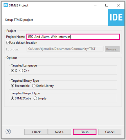
- File > New > STM32 Project in main panel.
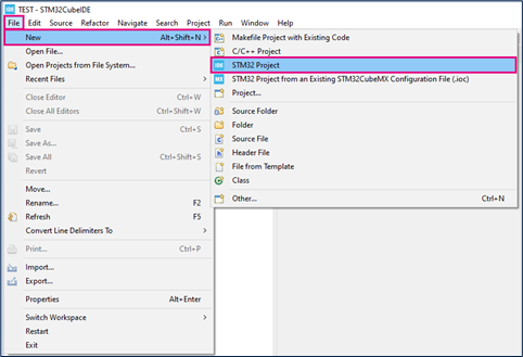
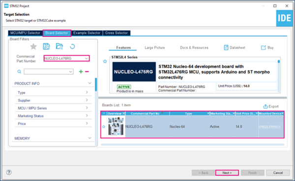
This example uses the NUCLEO-L476RG board.
- Select NUCLEO-L476RG board using Board Selector as shown in the figure below.
If the STM32L476 Cube library is not downloaded, it will download automatically. This however may take some time.
- Save the project.
- Initialize all peripherals with their default settings.
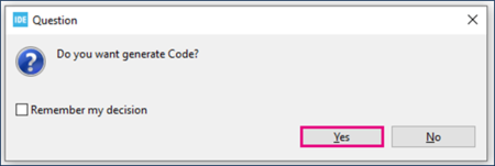
Answer “Yes” to initialize all peripherals with their default mode? Popup as below:

2.3. Configure RTC
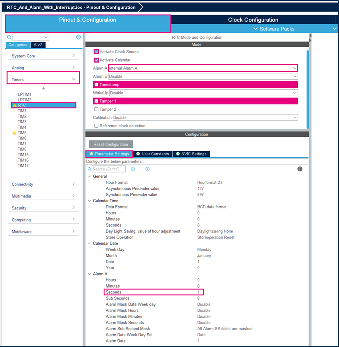
- Set Internal Alarm to Alarm A.
- Modify the seconds Alarm value to 1 in the parameter settings to set first Alarm to 1s.
- Enable alarm interrupt.
To enable the alarm interrupt, it is necessary to refer to the reference manual. The vectors table helps you select the correct RTC alarm interrupt.
STM32L476 has its RTC alarm interrupt connected to EXTI line as shown below:

2.4. Configure GPIO
Green Led of NUCLEO-L476RG board is connected to PA5. Set it to output push-pull mode so that it can be toggled as alarm indication.
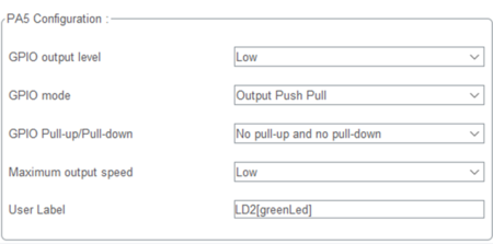
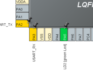
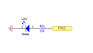
2.5. Generate project and edit main.c
- Click "Ctrl+S" to generate the project.
- Edit main.c
/* USER CODE BEGIN 4 */
void HAL_RTC_AlarmAEventCallback(RTC_HandleTypeDef *hrtc) {
  RTC_AlarmTypeDef sAlarm;
  HAL_RTC_GetAlarm(hrtc,&sAlarm,RTC_ALARM_A,FORMAT_BIN);
  if(sAlarm.AlarmTime.Seconds>58) {
    sAlarm.AlarmTime.Seconds=0;
  }else{
    sAlarm.AlarmTime.Seconds=sAlarm.AlarmTime.Seconds+1;
  }
    while(HAL_RTC_SetAlarm_IT(hrtc, &sAlarm, FORMAT_BIN)!=HAL_OK){}
    HAL_GPIO_TogglePin(GPIOA, GPIO_PIN_5);
}
/* USER CODE END 4 */
HAL_RTC_AlarmAEventCallback is called when the current time and date match the alarm time and date. In our example, it is set to 1 second in the future.
Then, we need to increment the alarm time by 1 second to make sure that the callback can be triggered once again. After 1 minute, current time and alarm time no longer match, therefore the alarm is not triggered and the LED stops blinking.
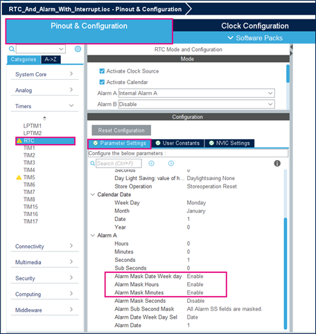
For example, in order to make our LED toggling infinite, alarm masks can be used to ignore days, hours and minutes.
In your main.c, search for the following line of code :
sAlarm.AlarmMask = RTC_ALARMMASK_NONE;
And replace it with the following :
sAlarm.AlarmMask = RTC_ALARMMASK_DATEWEEKDAY|RTC_ALARMMASK_HOURS|RTC_ALARMMASK_MINUTES;
An alternative procedure is possible in CubeMX as shown in the figure below. Don't forget to save the project and generate the code.
2.6. Compile and flash
